Page 2032 of 4770
N20951
A
Instrument Panel Wire Harness
No.1 Defroster Nozzle Garnish
Defroster Nozzle Assembly A
A
RH Side Defroster Duct Nozzle
No.1
Side Defroster
Duct Nozzle
A
A
A
A
A
ANo.2 Heater Duct to
Register
No.3 Instrument
Panel Register
Assembly K
K
K
K
K
K
No.1 Heater Duct to
RegisterAAA
No.1 Instrument Panel
Regigter AssemblyNo.2 Instrument
Panel Register
AssemblyInstrument
Panel Center
Bracket
Instrument PanelGlove Box
Light Assembly
± BODYINSTRUMENT PANEL
BO±73
2421 Author�: Date�:
Page 2038 of 4770
BO0MD±01
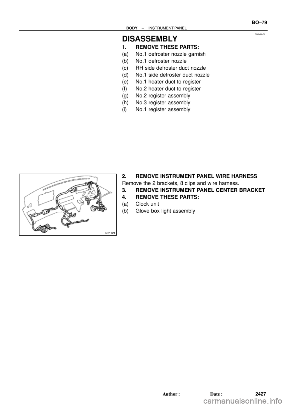
N21124
± BODYINSTRUMENT PANEL
BO±79
2427 Author�: Date�:
DISASSEMBLY
1. REMOVE THESE PARTS:
(a) No.1 defroster nozzle garnish
(b) No.1 defroster nozzle
(c) RH side defroster duct nozzle
(d) No.1 side defroster duct nozzle
(e) No.1 heater duct to register
(f) No.2 heater duct to register
(g) No.2 register assembly
(h) No.3 register assembly
(i) No.1 register assembly
2. REMOVE INSTRUMENT PANEL WIRE HARNESS
Remove the 2 brackets, 8 clips and wire harness.
3. REMOVE INSTRUMENT PANEL CENTER BRACKET
4. REMOVE THESE PARTS:
(a) Clock unit
(b) Glove box light assembly
Page 2151 of 4770

N21371
6
4
BE4029
Tester Probe
Tin FoilHeat Wire
BE0123
At Center
BE0124
0 VoltSeveral
Volts
Broken
Wire
± BODY ELECTRICALDEFOGGER SYSTEM
BE±57
2277 Author�: Date�:
5. w/ Heater:
INSPECT MIRROR DEFOGGER
(a) Connect the positive (+) lead from the battery to terminal
4 and the negative (±) lead to terminal 6.
(b) Check that the mirror becomes warm.
HINT:
It takes short time for the mirror to become warm.
6. INSPECT DEFOGGER WIRE
NOTICE:
�When cleaning the glass, use a soft, dry cloth, and
wipe the glass in the direction of the wire. Take care
not to damage the wires.
�Do not use detergents or glass cleaners with abrasive
ingredients.
�When measuring voltage, wind a piece of tin foil
around the top of the negative probe and press the foil
against the wire with your finger, as shown.
(a) Turn the ignition switch ON.
(b) Turn the defogger switch ON.
(c) Inspect the voltage at the center of each heat wire, as
shown.
VoltageCriteria
Approx. 5VOkay (No break in wire)
Approx.10V or 0VBroken wire
HINT:
If there is approximately 10 V, the wire is broken between the
center of the wire and the positive (+) end. If there is no voltage,
the wire is broken between the center of the wire and ground.
(d) Place the voltmeter positive (+) lead against the defogger
positive (+) terminal.
(e) Place the voltmeter negative (±) lead with the foil strip
against the heat wire at the positive (+) terminal end and
slide it toward the negative (±) terminal end.
(f) The point where the voltmeter deflects from zero to sever-
al V is the place where the heat wire is broken.
HINT:
If the heat wire is not broken, the voltmeter indicates 0 V at the
positive (+) end of the heat wire but gradually increases to about
12 V as the meter probe is moved to the other end.
Page 2177 of 4770

TMC made
(w/o Heater)TMMK made
(w/ Heater)1
2
2 332
± BODY")
BE0AW±03
Z16591
LR
MIRROR
OFF
LEFT SIDERIGHT SIDE
UP
OFF LEFT
RIGHT
DOWN
1 2 3
7 8 4
10 9 5
BE2357 h±10±2
6
N21184
TMMK made
(w/o Heater)
TMC made
(w/o Heater)TMMK made
(w/ Heater)1
2
2 332
± BODY ELECTRICALPOWER MIRROR CONTROL SYSTEM
BE±83
2303 Author�: Date�:
INSPECTION
1. Master switch left side:
INSPECT MIRROR CONTROL SWITCH CONTINUITY
Switch positionTester connectionSpecified condition
OFF±No continuity
UP1 ± 9, 6 ± 10Continuity
DOWN1 ± 10, 6 ± 9Continuity
LEFT5 ± 9, 6 ± 10Continuity
RIGHT5 ± 10, 6 ± 9Continuity
If continuity is not as specified, replace the switch.
2. Master switch right side:
INSPECT MIRROR CONTROL SWITCH CONTINUITY
Switch positionTester connectionSpecified condition
OFF±No continuity
UP6 ± 10, 7 ± 9Continuity
DOWN6 ± 9, 7 ± 10Continuity
LEFT6 ± 10, 8 ± 9Continuity
RIGHT6 ± 9, 8 ± 10Continuity
If continuity is not as specified, replace the switch.
3. INSPECT MIRROR MOTOR
(a) TMMK made (w/o Heater):
Connect the positive (+) lead from the battery to terminal
1 and negative (±) lead to terminal 2, check that the mirror
turns to left side.
(b) TMC made (w/o Heater):
Connect the positive (+) lead from the battery to terminal
3 and negative (±) lead to terminal 2, check that the mirror
turns to left side.
(c) TMMK made (w/ Heater):
Connect the positive (+) lead from the battery to terminal
3 and negative (±) lead to terminal 2, check that the mirror
turns to left side.
Page 2178 of 4770
N21185
TMMK made
(w/o Heater)
TMC made
(w/o Heater)TMMK made
(w/ Heater)
N21186
TMMK made
(w/o Heater)
TMC made
(w/o Heater)TMMK made
(w/ Heater) BE±84
± BODY ELECTRICALPOWER MIRROR CONTROL SYSTEM
2304 Author�: Date�:
(d) Reverse the polarity and check that the mirror turns to
right side.
(e) TMMK made (w/o Heater):
Connect the positive (+) lead from the battery to terminal
3 and the negative (±) lead to terminal 2, check that the
mirror turns upward.
(f) TMC made (w/o Heater):
Connect the positive (+) lead from the battery to terminal
1 and the negative (±) lead to terminal 2, check that the
mirror turns upward.
(g) TMMK made (w/ Heater):
Connect the positive (+) lead from the battery to terminal
1 and the negative (±) lead to terminal 2, check that the
mirror turns upward.
Page 2179 of 4770
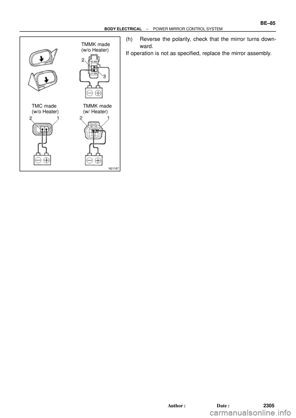
N21187
TMMK made
(w/o Heater)
TMC made
(w/o Heater)TMMK made
(w/ Heater)
± BODY ELECTRICALPOWER MIRROR CONTROL SYSTEM
BE±85
2305 Author�: Date�:
(h) Reverse the polarity, check that the mirror turns down-
ward.
If operation is not as specified, replace the mirror assembly.
Page 2298 of 4770
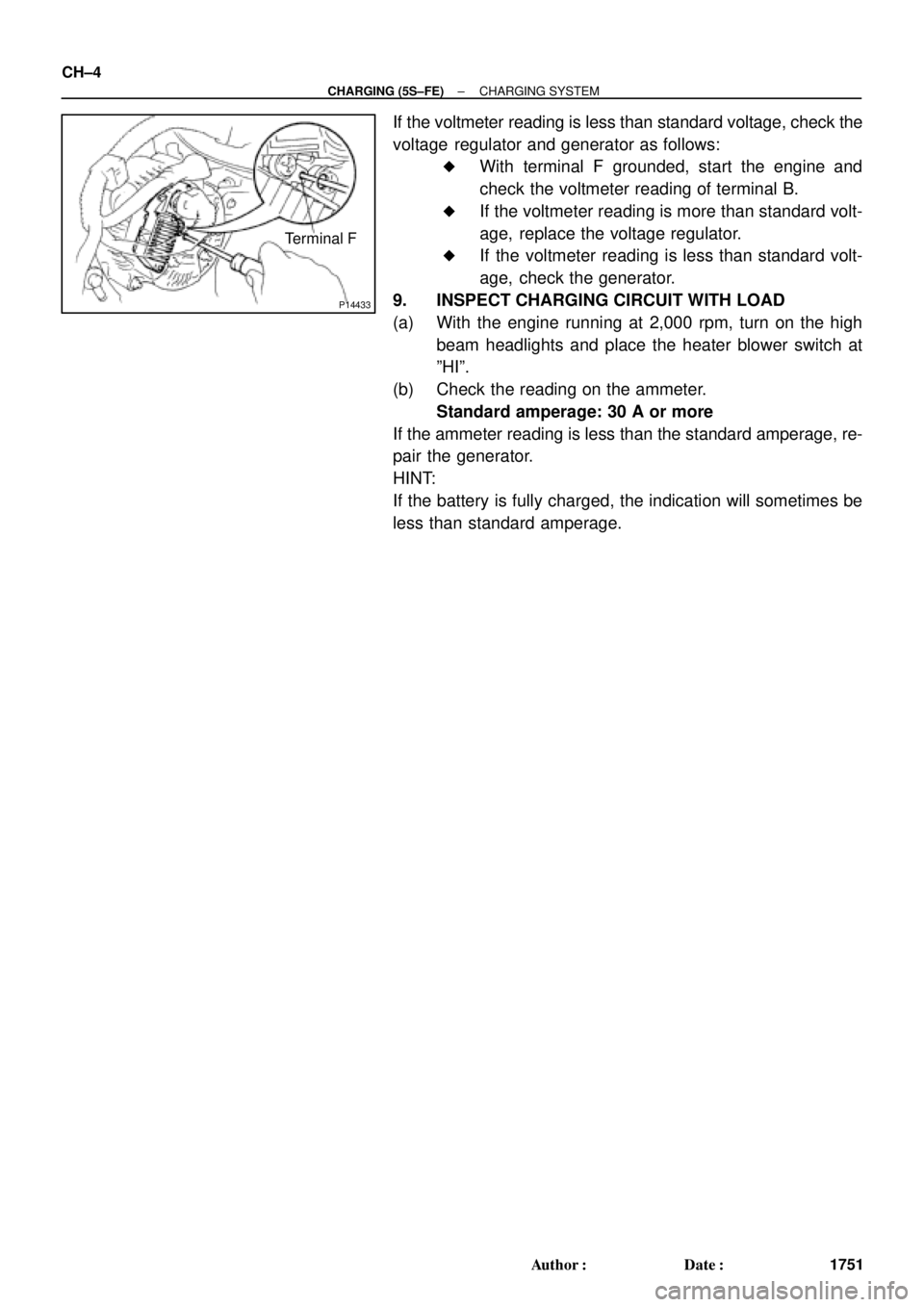
P14433
Terminal F CH±4
± CHARGING (5S±FE)CHARGING SYSTEM
1751 Author�: Date�:
If the voltmeter reading is less than standard voltage, check the
voltage regulator and generator as follows:
�With terminal F grounded, start the engine and
check the voltmeter reading of terminal B.
�If the voltmeter reading is more than standard volt-
age, replace the voltage regulator.
�If the voltmeter reading is less than standard volt-
age, check the generator.
9. INSPECT CHARGING CIRCUIT WITH LOAD
(a) With the engine running at 2,000 rpm, turn on the high
beam headlights and place the heater blower switch at
ºHIº.
(b) Check the reading on the ammeter.
Standard amperage: 30 A or more
If the ammeter reading is less than the standard amperage, re-
pair the generator.
HINT:
If the battery is fully charged, the indication will sometimes be
less than standard amperage.
Page 2314 of 4770
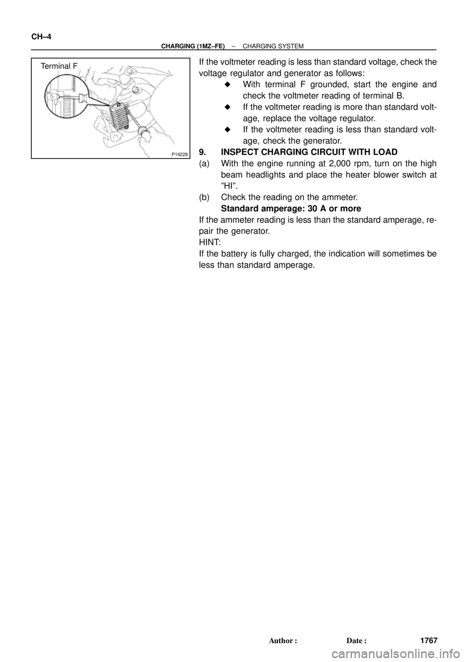
P14228
Terminal F CH±4
± CHARGING (1MZ±FE)CHARGING SYSTEM
1767 Author�: Date�:
If the voltmeter reading is less than standard voltage, check the
voltage regulator and generator as follows:
�With terminal F grounded, start the engine and
check the voltmeter reading of terminal B.
�If the voltmeter reading is more than standard volt-
age, replace the voltage regulator.
�If the voltmeter reading is less than standard volt-
age, check the generator.
9. INSPECT CHARGING CIRCUIT WITH LOAD
(a) With the engine running at 2,000 rpm, turn on the high
beam headlights and place the heater blower switch at
ºHIº.
(b) Check the reading on the ammeter.
Standard amperage: 30 A or more
If the ammeter reading is less than the standard amperage, re-
pair the generator.
HINT:
If the battery is fully charged, the indication will sometimes be
less than standard amperage.


TMC made
(w/o Heater)TMMK made
(w/ Heater)
N21186
TMMK made
(w/o Heater)
TMC made
(w/o Heater)TMMK made
(w/ Heater) BE±84
± BODY ELECTRICALPOWER MIRROR CONTROL SYSTEM
2")