Page 1593 of 4770
I09189
Magnetic Clutch
Relay
AC225±01
Z18060
35
1212 3
5
± AIR CONDITIONINGMAGNETIC CLUTCH RELAY
AC±71
2553 Author�: Date�:
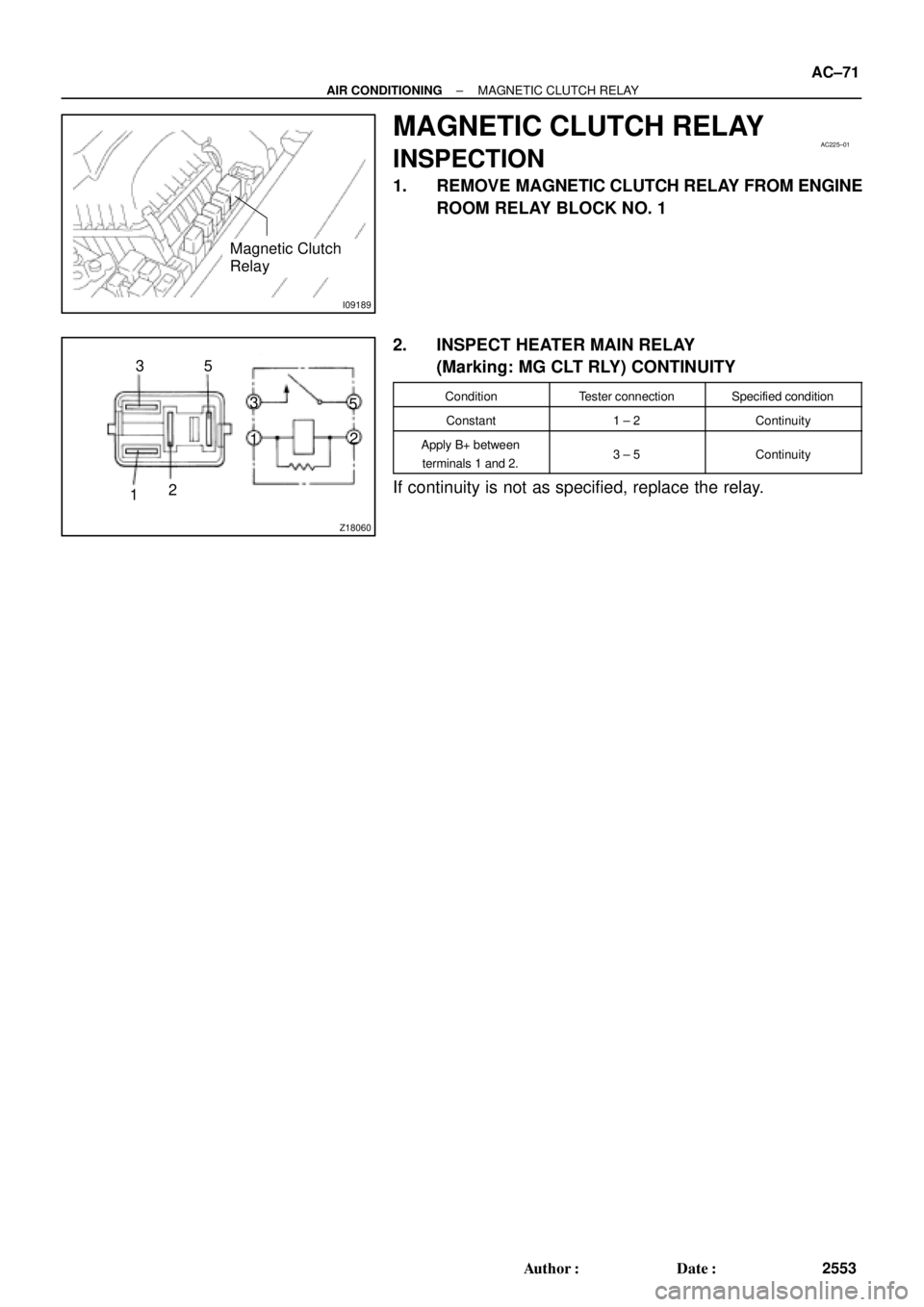
MAGNETIC CLUTCH RELAY
INSPECTION
1. REMOVE MAGNETIC CLUTCH RELAY FROM ENGINE
ROOM RELAY BLOCK NO. 1
2. INSPECT HEATER MAIN RELAY
(Marking: MG CLT RLY) CONTINUITY
ConditionTester connectionSpecified condition
Constant1 ± 2Continuity
Apply B+ between
terminals 1 and 2.3 ± 5Continuity
If continuity is not as specified, replace the relay.
Page 1603 of 4770
AC0ND±02
Z19017
LH Lower Instrument
Panel
No.1 Lower Finish
Panel
Cowl Side Trim
Front Door Inside
Scuff PlateCenter Cluster Finish Panel
A/C Control Assembly
Glove Compartment
Cowl Side Trim
Air Inlet Damper Control Cable
Air Inlet Control Lever
Mode Switch
A/C Switch
Defogger Switch
Heater Control
Name Sheet
Heater Control Knob Heater Control BaseBlower Speed Control
SwitchFront Door Inside Scuff Plate
± AIR CONDITIONINGAIR CONDITIONING CONTROL ASSEMBLY
AC±81
2563 Author�: Date�:
COMPONENTS
Page 1605 of 4770
AC0NF±02
± AIR CONDITIONINGAIR CONDITIONING CONTROL ASSEMBLY
AC±83
2565 Author�: Date�:
DISASSEMBLY
1. REMOVE A/C SWITCH AND DEFOGGER SWITCH
Using a screwdriver, release the claw and pull out the switch backward.
HINT:
Tape the screwdriver tip before use.
2. REMOVE HEATER CONTROL KNOBS
3. REMOVE HEATER CONTROL CABLE
4. REMOVE BLOWER SPEED CONTROL SWITCH
Remove the 2 screws and pull out the switch.
5. REMOVE MODE SWITCH
Remove the 2 screws and pull out the switch.
6. REMOVE HEATER CONTROL NAME SHEET
(a) Remove the 2 screws.
(b) Using a screwdriver, release the 4 claws and heater control name sheet.
HINT:
Tape the screwdriver tip before use.
Page 1621 of 4770

INTRODUCTIONGLOSSARY OF SAE AND TOYOTA TERMS ±
IN±6
GLOSSARY OF SAE AND TOYOTA TERMS
This glossary lists all SAE±J1930 terms and abbreviations used in this manual in compliance with SAE
recommendations, as well as their Toyota equivalents.
SAE
ABBREVIATIONSSAE TERMSTOYOTA TERMS
( )±±ABBREVIATIONS
A/CAir ConditioningAir Conditioner
ACLAir CleanerAir Cleaner
AIRSecondary Air InjectionAir Injection (AI)
APAccelerator Pedal±
B+Battery Positive Voltage+B, Battery Voltage
BAROBarometric Pressure±
CACCharge Air CoolerIntercooler
CARBCarburetorCarburetor
CFIContinuous Fuel Injection±
CKPCrankshaft PositionCrank Angle
CLClosed LoopClosed Loop
CMPCamshaft PositionCam Angle
CPPClutch Pedal Position±
CTOXContinuous Trap Oxidizer±
CTPClosed Throttle Position±
DFIDirect Fuel Injection (Diesel)Direct Injection (DI)
DIDistributor Ignition±
DLC1
DLC2
DLC3Data Link Connector 1
Data Link Connector 2
Data Link Connector 31: Check Connector
2: Toyota Diagnosis Communication Link (TDCL)
3: OBD@@@@@: [g 2] Diagnostic Connector
DTCDiagnostic Trouble CodeDiagnostic Code
DTMDiagnostic Test Mode±
ECLEngine Control Level±
ECMEngine Control ModuleEngine ECU (Electronic Control Unit)
ECTEngine Coolant TemperatureCoolant Temperature, Water Temperature (THW)
EEPROMElectrically Erasable Programmable Read Only
MemoryElectrically Erasable Programmable Read Only Memory
(EEPROM),
Erasable Programmable Read Only Memory(EPROM)
EFEEarly Fuel EvaporationCold Mixture Heater (CMH), Heat Control Valve (HCV)
EGRExhaust Gas RecirculationExhaust Gas Recirculation (EGR)
EIElectronic IgnitionToyota Distributorless Ignition (TDI)
EMEngine ModificationEngine Modification (EM)
EPROMErasable Programmable Read Only MemoryProgrammable Read Only Memory (PROM)
EVAPEvaporative EmissionEvaporative Emission Control (EVAP)
FCFan Control±
FEEPROMFlash Electrically Erasable Programmable
Read Only Memory±
FEPROMFlash Erasable Programmable Read Only Memory±
FFFlexible Fuel±
FPFuel PumpFuel Pump
GENGeneratorAlternator
GNDGroundGround (GND)
HO2SHeated Oxygen SensorHeated Oxygen Sensor (HO2S)
IN016±02
Page 1791 of 4770

INTRODUCTIONGLOSSARY OF SAE AND TOYOTA TERMS ±
IN±6
GLOSSARY OF SAE AND TOYOTA TERMS
This glossary lists all SAE±J1930 terms and abbreviations used in this manual in compliance with SAE
recommendations, as well as their Toyota equivalents.
SAE
ABBREVIATIONSSAE TERMSTOYOTA TERMS
( )±±ABBREVIATIONS
A/CAir ConditioningAir Conditioner
ACLAir CleanerAir Cleaner
AIRSecondary Air InjectionAir Injection (AI)
APAccelerator Pedal±
B+Battery Positive Voltage+B, Battery Voltage
BAROBarometric Pressure±
CACCharge Air CoolerIntercooler
CARBCarburetorCarburetor
CFIContinuous Fuel Injection±
CKPCrankshaft PositionCrank Angle
CLClosed LoopClosed Loop
CMPCamshaft PositionCam Angle
CPPClutch Pedal Position±
CTOXContinuous Trap Oxidizer±
CTPClosed Throttle Position±
DFIDirect Fuel Injection (Diesel)Direct Injection (DI)
DIDistributor Ignition±
DLC1
DLC2
DLC3Data Link Connector 1
Data Link Connector 2
Data Link Connector 31: Check Connector
2: Toyota Diagnosis Communication Link (TDCL)
3: OBD@@@@@: [g 2] Diagnostic Connector
DTCDiagnostic Trouble CodeDiagnostic Code
DTMDiagnostic Test Mode±
ECLEngine Control Level±
ECMEngine Control ModuleEngine ECU (Electronic Control Unit)
ECTEngine Coolant TemperatureCoolant Temperature, Water Temperature (THW)
EEPROMElectrically Erasable Programmable Read Only
MemoryElectrically Erasable Programmable Read Only Memory
(EEPROM),
Erasable Programmable Read Only Memory(EPROM)
EFEEarly Fuel EvaporationCold Mixture Heater (CMH), Heat Control Valve (HCV)
EGRExhaust Gas RecirculationExhaust Gas Recirculation (EGR)
EIElectronic IgnitionToyota Distributorless Ignition (TDI)
EMEngine ModificationEngine Modification (EM)
EPROMErasable Programmable Read Only MemoryProgrammable Read Only Memory (PROM)
EVAPEvaporative EmissionEvaporative Emission Control (EVAP)
FCFan Control±
FEEPROMFlash Electrically Erasable Programmable
Read Only Memory±
FEPROMFlash Erasable Programmable Read Only Memory±
FFFlexible Fuel±
FPFuel PumpFuel Pump
GENGeneratorAlternator
GNDGroundGround (GND)
HO2SHeated Oxygen SensorHeated Oxygen Sensor (HO2S)
IN016±02
Page 1983 of 4770

H01759
UTA: IMI:
TOKAIRIKA:
Mirror
Mirror Shell
Gasket
Mirror w/case
Wire Retainer
Mirror w/case
Clip X4
BO0LB±01
H01760
Mirror w/caseGasket
Mirror HousingWire Retainer
H01761
Pivot Mirror Housing Forward
H01762
Mirror
Glass
Terminals
Mirror CaseScraper BO±24
± BODYOUTSIDE REAR VIEW MIRROR
2372 Author�: Date�:
DISASSEMBLY
1. IDENTIFY OUTSIDE REAR VIEW MIRROR
(a) w/ Power Rear View Mirror:
UTA:
The mirror moves smoothly when pressing the end of the
mirror inward.
(b) w/ Power Rear View Mirror:
IMI:
The mirror stutters when pressing the end of the mirror in-
ward.
(c) w/ Power Rear View Mirror:
TOKAIRIKA:
Equipped only on vehicles manufactured by TMC.
(d) w/o Power Rear View Mirror:
Mirrors manufactured by IMI
2. UTA:
DISASSEMBLE OUTSIDE REAR VIEW MIRROR
(a) Disconnect the battery.
(b) Press the inboard end of the mirror inward to access the
rear of the mirror w/case assembly.
(c) Unlatch both ends of the wire retainer, then remove the
mirror parts from the mirror housing.
NOTICE:
Be careful not to damage the wires on heated mirrors. Dis-
connect the wires from the back side of the heater.
3. IMI:
DISASSEMBLE OUTSIDE REAR VIEW MIRROR
(a) w/Heated Mirrors:
Disconnect the battery.
(b) Protect the door surface.
(c) Pivot the mirror housing to the forward position.
(d) Insert a scraper between the mirror and the case to re-
move the mirror.
NOTICE:
Be careful not to damage the wires on heated mirrors. Dis-
connect the wires from the back side of the heater.
Page 1984 of 4770
H01763
Mirror
Housing
Shop Towel
± BODYOUTSIDE REAR VIEW MIRROR
BO±25
2373 Author�: Date�:
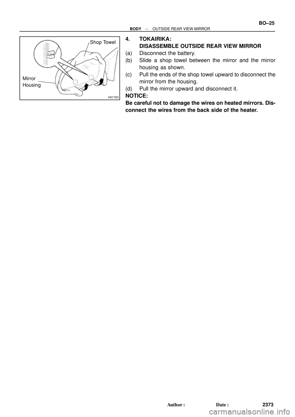
4. TOKAIRIKA:
DISASSEMBLE OUTSIDE REAR VIEW MIRROR
(a) Disconnect the battery.
(b) Slide a shop towel between the mirror and the mirror
housing as shown.
(c) Pull the ends of the shop towel upward to disconnect the
mirror from the housing.
(d) Pull the mirror upward and disconnect it.
NOTICE:
Be careful not to damage the wires on heated mirrors. Dis-
connect the wires from the back side of the heater.
Page 1985 of 4770

H01764
Gasket
Mirror w/case
Mirror HousingWire Retainer
BO0LC±01
H01765
50±60 mm
H01766
Glass
Case
Edge
H01767
Claw BClaw A BO±26
± BODYOUTSIDE REAR VIEW MIRROR
2374 Author�: Date�:
REASSEMBLY
1. UTA:
ASSEMBLE OUTSIDE REAR VIEW MIRROR
(a) w/Heated Mirrors:
Connect the heater wires.
(b) Install the wire retainer onto the mirror w/case assembly,
then press the mirror firmly into place to engage the 6 lugs
of the wire retainer.
NOTICE:
Pull the mirror edges to confirm the wire retainer lugs com-
pletely engage with the mirror housing.
(c) Reconnect the battery, then operate the mirror to its full
stop position.
2. IMI:
ASSEMBLE OUTSIDE REAR VIEW MIRROR
(a) From a distance of 50±60 mm, use a heat gun or hair dry-
er to heat the edge of the mirror case until the mirror case
becomes soft.
CAUTION:
Use extreme caution when using a heat gun or hair dryer.
Holding it too close can melt the mirror case.
(b) w/ Heated Mirrors:
Connect the heater wires.
(c) Before the the case cools down, position and snap the
new mirror glass into the case.
NOTICE:
Verify the glass case edge completely surrounds the mirror
glass.
(d) Allow the case to cool down before moving the mirror
back to its operating position.
(e) Recheck the fit between the glass and the case.
(f) Reconnect the battery, then operate the mirror to its full
stop position.
3. TOKAIRIKA:
ASSEMBLE OUTSIDE REAR VIEW MIRROR
(a) w/ Heated Mirrors:
Connect the heater wires.
(b) Connect the claws (A) and install the mirror into the mirror
housing.
(c) Push the mirror inward to connect the claws (B) onto the
mirror housing.
(d) Reconnect the battery, then operate the mirror to its full
stop position.