Page 1550 of 4770

I03838
SST
I03839
PushSST
Pull
SST
Release
Lever
I06919
Disconnect the tube
using hand
Screw
Driver
Tube
I06878
Correct Wrong
Gap
N20281
AC±28
± AIR CONDITIONINGAIR CONDITIONING UNIT
2510 Author�: Date�:
(1) Inert SST to piping clamp.
HINT:
Confirm the direction of the piping clamp claw and SST using
the illustration showing on the caution label.
(2) Push down SST and release the clamp lock.
NOTICE:
Be careful not to deform the tubes, when pushing SST.
(3) Pull SST slightly and push the release lever, then re-
move the piping clamp with SST.
(4) Remove the piping clamp from SST.
(b) Disconnect the both tubes.
NOTICE:
�Do not use tools like screwdriver to remove the tube.
�Cap the open fittings immediately to keep moisture or
dirt out of the system.
HINT:
At the time of installation, please refer to the following item.
�Lubricate 4 new O±rings with compressor oil and install
the tubes.
�After connection, check the fitting for claw of the piping
clamp.
7. REMOVE A/C UNIT
(a) Disconnect the connector.
(b) Slide the floor carpet backward.
(c) Remove the rear heater duct.
(d) Remove the 2 nuts and A/C unit.
Page 1551 of 4770
 Relea")
AC21X±01
N20287
N20283
N20243
x13Water Seal
Plate
EvaporatorInsurator
N20293
± AIR CONDITIONINGAIR CONDITIONING UNIT
AC±29
2511 Author�: Date�:
DISASSEMBLY
1. REMOVE AIR OUTLET SERVOMOTOR
(a) Release the claw and pull out the plate.
(b) Remove the 3 screws and servomotor.
2. REMOVE HEATER RADIATOR
(a) Remove the 3 screws and 3 plates.
(b) Remove the 2 clips and heater radiator pipes.
(c) Pull out the heater radiator.
3. REMOVE THESE FOOT AIR DUCT LH
4. REMOVE EXPANSION VALVE
(a) Remove piping clamp.
(b) Remove the packings.
(c) Using a hexagon wrench (5.0 mm, 0.20 in.), remove the
2 bolts and separate the expansion valve and evaporator.
5. REMOVE EVAPORATOR
(a) Remove the grommet from the evaporator.
(b) Using a knife, cut off each packings.
HINT:
Do not reuse the packing.
(c) Remove the 13 screws and separate the heater cases,
then remove the evaporator and water seal.
(d) Release the 4 claws and remove the plate from the evap-
orator.
6. PEEL OFF THE WATER SEAL FROM HEATER UNIT
7. REMOVE THERMISTOR
Pull out the thermistor with the holders.
Page 1553 of 4770
 Install the p")
AC0LX±02
N21046
N21045
Packing Paper
N21044
± AIR CONDITIONINGAIR CONDITIONING UNIT
AC±31
2513 Author�: Date�:
REASSEMBLY
1. INSTALL THERMISTOR TO EVAPORATOR
2. INSTALL EVAPORATOR
(a) Install the plate to the evaporator.
(b) Install the evaporator on the insulator.
(c) Connect the heater case with the 13 screws.
NOTICE:
The packing for water seal should be replaced, with a new
one when the A/C unit is reassembled.
(d) Install the 2 new packings.
(e) Install the grommet to evaporator.
HINT:
If evaporator is replaced, add compressor oil to the compressor.
Add 40 ± 50 cc (1.4 ± 1.7 fl.oz.)
Compressor oil: ND ± OIL 8 or equivalent
3. INSTALL EXPANSION VALVE
(a) Lubricate 2 new O±rings with compressor oil and install
the tubes.
(b) Install the liquid tube and suction tube on the expansion
valve.
(c) Using a knife, cut off packing paper of packing while peel
off the paper, as shown in the illustration.
HINT:
Leave the packing paper untaped on the tube side so that the
installation bolt hole for remains visible.
(d) Apply new packing.
NOTICE:
Do not overtape the packing beyond the expansion valve
edge.
Page 1554 of 4770
N20283
N20245
Pin
Pin AC±32
± AIR CONDITIONINGAIR CONDITIONING UNIT
2514 Author�: Date�:
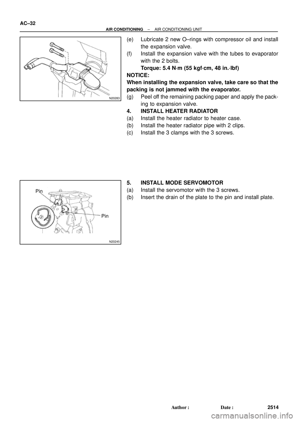
(e) Lubricate 2 new O±rings with compressor oil and install
the expansion valve.
(f) Install the expansion valve with the tubes to evaporator
with the 2 bolts.
Torque: 5.4 N´m (55 kgf´cm, 48 in.´lbf)
NOTICE:
When installing the expansion valve, take care so that the
packing is not jammed with the evaporator.
(g) Peel off the remaining packing paper and apply the pack-
ing to expansion valve.
4. INSTALL HEATER RADIATOR
(a) Install the heater radiator to heater case.
(b) Install the heater radiator pipe with 2 clips.
(c) Install the 3 clamps with the 3 screws.
5. INSTALL MODE SERVOMOTOR
(a) Install the servomotor with the 3 screws.
(b) Insert the drain of the plate to the pin and install plate.
Page 1578 of 4770
AC21Z±01
N20692
I09156
I09155
I09154
AC±56
± AIR CONDITIONINGHEATER RADIATOR
2538 Author�: Date�:
HEATER RADIATOR
REMOVAL
1. DRAIN ENGINE COOLANT FROM RADIATOR
HINT:
It is not necessary to drain out all the coolant.
2. DISCONNECT WATER HOSES FROM A/C UNIT
(See page AC±27)
3. REMOVE NO. 1 LOWER INSTRUMENT PANEL
4. REMOVE LH INSTRUMENT LOWER PANEL
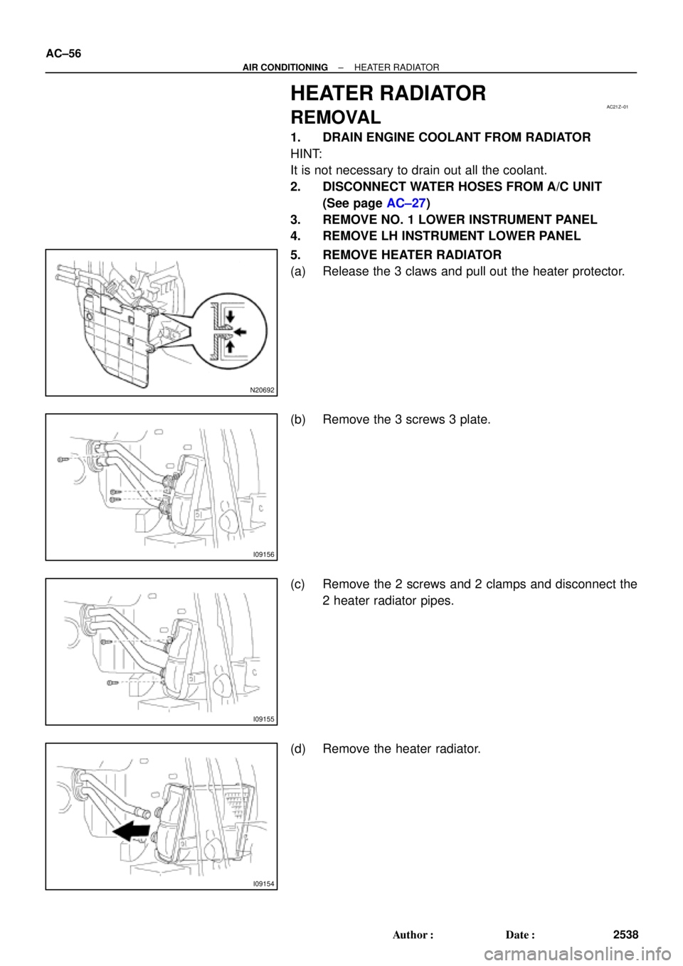
5. REMOVE HEATER RADIATOR
(a) Release the 3 claws and pull out the heater protector.
(b) Remove the 3 screws 3 plate.
(c) Remove the 2 screws and 2 clamps and disconnect the
2 heater radiator pipes.
(d) Remove the heater radiator.
Page 1579 of 4770
AC0MK±01
± AIR CONDITIONINGHEATER RADIATOR
AC±57
2539 Author�: Date�:
INSPECTION
INSPECT FINS FOR BLOCKAGE
If the fins are clogged, clean them with compressed air.
Page 1580 of 4770
AC0ML±01
AC±58
± AIR CONDITIONINGHEATER RADIATOR
2540 Author�: Date�:
INSTALLATION
Installation is in the reverse order of removal (See page AC±56).
Page 1592 of 4770
I09189
Heater Main
Relay
AC224±01
Z19533
34
5
1212 34 5 AC±70
± AIR CONDITIONINGHEATER MAIN RELAY
2552 Author�: Date�:
HEATER MAIN RELAY
INSPECTION
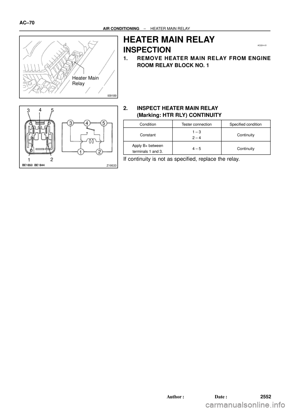
1. REMOVE HEATER MAIN RELAY FROM ENGINE
ROOM RELAY BLOCK NO. 1
2. INSPECT HEATER MAIN RELAY
(Marking: HTR RLY) CONTINUITY
ConditionTester connectionSpecified condition
Constant1 ± 3
2 ± 4Continuity
Apply B+ between
terminals 1 and 3.4 ± 5Continuity
If continuity is not as specified, replace the relay.