Page 1516 of 4770
AC2CL±01
I12253I12254
I12260
LH Lower Instrument
Panel
No.1 Lower Finish
Panel
Cowl Side Trim
Front Door Inside
Scuff PlateCenter Cluster Finish Panel
A/C Control Assembly
Glove Compartment
Cowl Side Trim
Mode Switch
A/C Switch
Defogger Switch
Heater Control
Name Sheet
Heater Control Knob Heater Control Base Blower Speed Control
SwitchFront Door Inside Scuff Plate
Air Intake Switch
AC±94± AIR CONDITIONINGAIR CONDITIONING CONTROL ASSEMBLY (Manual
A/C)
2582 Author�: Date�:
2001 CAMRY (RM819U)
COMPONENTS
Page 1518 of 4770
AC2CN±01
AC±96± AIR CONDITIONINGAIR CONDITIONING CONTROL ASSEMBLY (Manual
A/C)
2584 Author�: Date�:
2001 CAMRY (RM819U)
DISASSEMBLY
1. REMOVE A/C SWITCH, AIR INTAKE SWITCH AND DEFOGGER SWITCH
Using a screwdriver, release the claw and pull out the switch backward.
HINT:
Tape the screwdriver tip before use.
2. REMOVE HEATER CONTROL KNOBS
3. REMOVE HEATER CONTROL CABLE
4. REMOVE BLOWER SPEED CONTROL SWITCH
Remove the 2 screws and pull out the switch.
5. REMOVE MODE SWITCH
Remove the 2 screws and pull out the switch.
6. REMOVE HEATER CONTROL NAME SHEET
(a) Remove the 2 screws.
(b) Using a screwdriver, release the 4 claws and heater control name sheet.
HINT:
Tape the screwdriver tip before use.
Page 1521 of 4770
AC±99
2587 Author�: Date�:
2001 CAMRY (RM819U)
9. INSPECT AIR INTAKE SWITCH CIRCUIT
(a) Connect the connectors to heater con")
I12257
± AIR CONDITIONINGAIR CONDITIONING CONTROL ASSEMBLY (Manual
A/C)AC±99
2587 Author�: Date�:
2001 CAMRY (RM819U)
9. INSPECT AIR INTAKE SWITCH CIRCUIT
(a) Connect the connectors to heater control assembly.
(b) Inspect wire harness side connector from the back side,
as shown in the chart.
Tester connectionConditionSpecified condition
7 ± GroundConstantContinuity
8 ± GroundConstantContinuity
3G dIG ON. Light control switch: TAILBattery positive voltage3 ± GroundIG ON. Light control switch: OFFNo voltage
4 ± GroundConstantBattery positive voltage
5G dIgnition switch: ONBattery positive voltage5 ± GroundIgnition switch: LOCK or ACC.No voltage
2G dIG ON. Mode selector: DEF.Below 0.3 V2 ± GroundIG ON. Mode selector: Except DEF.No voltage
6G dIG ON. Mode selector: F/DBelow 0.3 V6 ± GroundIG ON. Mode selector: Except F/DNo voltage
9G dIG ON. Air intake switch: RECBelow 2.0 V9 ± GroundIG ON. Air intake switch: FRSNo voltage
10 G dIG ON. Air intake switch: FRSBelow 2.0 V10 ± GroundIG ON. Air intake switch: RECNo voltage
If circuit is as specified, try replacing the air intake switch with
a new one. If the circuit is not as specified, inspect the circuits
connected to other parts.
10. INSPECT REAR DEFOGGER SWITCH OPERATION
(See page BE±57)
Page 1535 of 4770
AC0LL±02
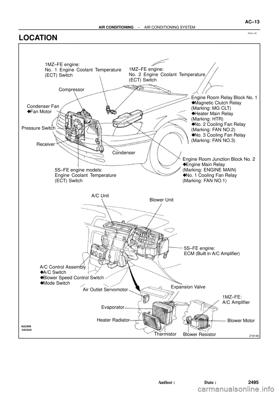
Z19146
1MZ±FE engine:
No. 1 Engine Coolant Temperature
(ECT) Switch
Compressor
Engine Room Junction Block No. 2
� Engine Main Relay
(Marking: ENGINE MAIN)
� No. 1 Cooling Fan Relay
(Marking: FAN NO.1)Engine Room Relay Block No. 1
� Magnetic Clutch Relay
(Marking: MG CLT)
� Heater Main Relay
(Marking: HTR)
� No. 2 Cooling Fan Relay
(Marking: FAN NO.2)
� No. 3 Cooling Fan Relay
(Marking: FAN NO.3)
5S±FE engine models:
Engine Coolant Temperature
(ECT) Switch Receiver Pressure SwitchCondenser Fan
� Fan Motor1MZ±FE engine:
No. 2 Engine Coolant Temperature
(ECT) Switch
Condenser
Blower Unit A/C Unit
A/C Control Assembly
� A/C Switch
� Blower Speed Control Switch
� Mode Switch
Air Outlet Servomotor
Heater Radiator
Thermistor
Blower ResistorBlower Motor 1MZ±FE:
A/C Amplifier Expansion Valve5S±FE engine:
ECM (Built in A/C Amplifier)
Evaporator
± AIR CONDITIONINGAIR CONDITIONING SYSTEM
AC±13
2495 Author�: Date�:
LOCATION
Page 1536 of 4770

AC21T±01
AC±14
± AIR CONDITIONINGTROUBLESHOOTING
2496 Author�: Date�:
TROUBLESHOOTING
PROBLEM SYMPTOMS TABLE
Use the table below to help you find the cause of the problem. The numbers indicate the priority of the likely
cause of the problem. Check each part in order. If necessary, replace these parts.
SymptomSuspect AreaSee page
No blower operation
4. HTR Fuse
5. Heater main relay
6. Blower motor
7. Blower resistor
8. Blower speed control switch
9. Wire harness±
AC±70
AC±63
AC±64
AC±84
±
No air temperature control1. Engine coolant volume
2. A/C control assembly±
AC±80
No air inlet control1. A/C control assemblyAC±80
No air outlet control
1. HTR Fuse
2. Air outlet servomotor
3. Mode switch±
AC±65
AC±84
No compressor operation
1. Refrigerant volume
2. A.C Fuse
3. HTR Fuse
4. Magnetic clutch relay
5. Magnetic clutch
6. Compressor
7. Pressure switch
8. Heater main relay
9. Blower speed control switch
10.A/C switch
11. *1 ECM
*
2 A/C amplifier
12.Wire harness
AC±3
±
±
AC±71
AC±39
AC±39
AC±67
AC±70
AC±84
AC±84
DI±218
AC±88
±
No compressor operates intermittently
1. Refrigerant volume
2. Condenser fan
3. Pressure switch
4. *1 ECM
*2 A/C amplifier
5. Thermistor
6. Wire harnessAC±3
AC±74
AC±67
DI±218
AC±88
AC±24
±
No cool air comes out
1. Refrigerant volume
2. Refrigerant pressure
3. Drive belt
4. Compressor lock sensor
5. Magnetic clutch
6. Compressor
7. Pressure switch
8. Thermistor
9. A/C switch
10.*1 ECM
*2 A/C amplifier
11. Wire harnessAC±3
AC±3
AC±16
AC±16
AC±39
AC±39
AC±67
AC±24
AC±84
DI±218
AC±88
±
Page 1537 of 4770

± AIR CONDITIONINGTROUBLESHOOTING
AC±15
2497 Author�: Date�:
Cool air comes out only at high engine rpm
1. Refrigerant volume
2. Drive belt
3. Magnetic clutch
4. Compressor
5. Condenser
6. Condenser fan
7. Receiver
8. Expansion valve
9. Evaporator
10.Thermistor
11. Refrigerant line
12.Pressure switch
13.*
1 ECM
*2 A/C amplifier
AC±3
AC±16
AC±16
AC±39
AC±52
AC±74
AC±49
AC±59
AC±30
AC±24
AC±21
AC±67
DI±218
AC±88
No engine idle±up when A/C switch ON
1. *1 ECM
*2 A/C amplifier
2. Wire harness
DI±218
AC±88
±
Blinking of A/C indicator
1. *1 ECM
*2 A/C amplifier
2. Thermistor
3. Compressor
DI±218
AC±88
AC±24
AC±39
A/C indicator does not lights up when turn mode switch to DEF.
position
1. A/C Fuse
2. Mode switch
3. A/C switch
4. *
1 ECM
*2 A/C amplifier
5. Wire harness
±
AC±84
AC±84
DI±218
AC±88
±
No warm air comes out
1. Engine coolant volume
2. A/C control assembly
3. Heater radiator±
AC±80
AC±57
No condenser fan operation
1. CDS FAN Fuse
2. Engine main relay
3. Cooling fan relay No. 1
4. Cooling fan relay No. 2
5. Cooling fan relay No. 3
6. Condenser fan motor
7. Pressure switch
8. *
1 Engine coolant temp. switch
*2 No. 1 Engine coolant temp. switch
9. *2No. 2 Engine coolant temp. switch
10.Wire harness
±
±
AC±72
AC±72
AC±72
AC±74
AC±67
AC±92
AC±92
AC±92
±
*1: 5S±FE Engine Models
*
2: 1MZ±FE Engine Models
Page 1548 of 4770
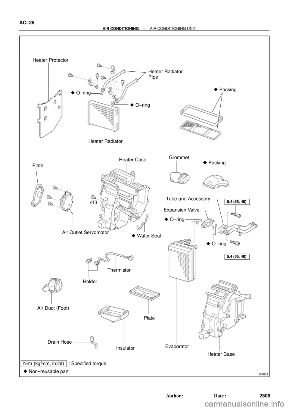
I07051
Heater Protector
Heater Radiator
Pipe
� Packing
� O±ring
� O±ring
Heater Radiator
Plate
Heater CaseGrommet
� Packing
x13
Air Outlet Servomotor� Water Seal
Air Duct (Foot)
Holder
Thermistor
5.4 (55, 48)
5.4 (55, 48)
� O±ring
� O±ring
Tube and Accessory
Expansion Valve
Drain Hose
Insulator
Plate
Evaporator
Heater Case
N´m (kgf´cm, in:lbf) : Specified torque
� Non±reusable part
AC±26
± AIR CONDITIONINGAIR CONDITIONING UNIT
2508 Author�: Date�:
Page 1549 of 4770

AC21W±01
N20288
N20237
Water Hose
MarkingUpper
LH
Hose ClipRH Heater Radiator Pipe
45 ± 10°
Lower
I09160
± AIR CONDITIONINGAIR CONDITIONING UNIT
AC±27
2509 Author�: Date�:
REMOVAL
1. DISCHARGE REFRIGERANT FROM REFRIGERATION
SYSTEM
HINT:
At the time of installation, please refer to the following item.
Evacuate air from refrigeration system.
Charge system with refrigerant and inspect for leakage of refrig-
erant.
Specified amount: 800 ± 50 g (28.22 ± 1.76 oz.)
2. DRAIN ENGINE COOLANT FROM RADIATOR
HINT:
It is not necessary to drain out all the coolant.
3. DISCONNECT WATER HOSE FROM HEATER RADIA-
TOR PIPES
(a) Using pliers, grip the claws of the hose clip and slide the
hose clip along the hose.
(b) Disconnect the water hose.
HINT:
At the time of installation, please refer to the following items.
�Push the water hose onto the heater radiator pipe as far
as ridge on the pipe and install the hose clip.
�Install the hose clip in a position, as shown in the illustra-
tion.
4. REMOVE BLOWER UNIT (See page AC±35)
5. REMOVE INSTRUMENT PANEL AND REINFORCE-
MENT (See page BO±75)
6. DISCONNECT LIQUID AND SUCTION TUBES
(a) Using SST, remove the 2 piping clamps.
SST 09870±00015 (Suction tube)
09870±00025 (Liquid tube)