Page 3049 of 4770
± DIAGNOSTICSSUPPLEMENTAL RESTRAINT SYSTEM
DI±629
864 Author�: Date�:
7. RELEASE METHOD OF AIRBAG ACTIVATION PRE-
VENTION MECHANISM
An airbag activation prevention mechanism is built into the con-
nector for the squib circuit of the SRS.
When release of the airbag activation prevention mechanism is
directed in the troubleshooting procedure, as shown in the il-
lustration of the connectors on the next pages, insert paper
which is the same thickness as the male terminal, between the
terminal and the short spring.
CAUTION:
Never release the airbag activation prevention mechanism
on the steering wheel pad connector.
NOTICE:
�Do not release the airbag activation prevention mech-
anism unless specifically directed by the trouble-
shooting procedure.
�If the inserted paper is too thick the terminal and short
spring may be damaged, so always use paper with
the same thickness as the male terminal.
Page 3050 of 4770
H08316
TMC made :
Side Airbag Assembly (LH)
(Squib) Side Airbag Sensor (LH)Side Airbag Sensor (RH)Side Airbag Assembly (RH)
(Squib)
Seat Belt
Pretensioner (RH)
Airbag Sensor
AssemblyFront Passenger Airbag Assembly (Squib)
Spiral Cable
No.1 J/B 2
37 8
10
11
12
13
1
4
5
6
9
Steering Wheel
Pad (Squib) Front Airbag Sensor (RH)
Front Airbag Sensor (LH)
Seat Belt
Pretensioner (LH) 14
15
16
DI±630
± DIAGNOSTICSSUPPLEMENTAL RESTRAINT SYSTEM
865 Author�: Date�:
Page 3051 of 4770
H08247
Airbag Sensor
AssemblySide Airbag Assembly (RH)
(Squib)
Seat Belt
Pretensioner (RH)
Side Airbag Sensor (RH)
Front Passenger Airbag
Assembly (Squib)
Spiral Cable
Steering Wheel
Pad (Squib)
No.1 J / B
Side Airbag Sensor (LH)
Side Airbag Assembly (LH)
(Squib)1
2
3
4
5
6
7
14
9
10
1112
13
8
15 TMMK made :
Seat Belt
Pretensioner (LH)
16
17
18
Front Airbag Sensor (RH)
Front Airbag Sensor (LH)
± DIAGNOSTICSSUPPLEMENTAL RESTRAINT SYSTEM
DI±631
866 Author�: Date�:
Page 3053 of 4770

DI1AZ±04
± DIAGNOSTICSSUPPLEMENTAL RESTRAINT SYSTEM
DI±633
868 Author�: Date�:
DIAGNOSTIC TROUBLE CODE CHART
If a malfunction code is displayed during the DTC check, check the circuit listed for that code in the table
below (Proceed to the page given for that circuit.).
DTC No.
(See Page)Detection ItemTrouble AreaSRS
Warning Light
B0100/13
(DI±640)
�Short in D squib circuit�Steering wheel pad (squib)
�Spiral cable
�Airbag sensor assembly
�Wire harness
ON
B0101/14
(DI±645)
�Open in D squib circuit�Steering wheel pad (squib)
�Spiral cable
�Airbag sensor assembly
�Wire harness
ON
B0102/11
(DI±649)
�Short in D squib circuit (to Ground)�Steering wheel pad (squib)
�Spiral cable
�Airbag sensor assembly
�Wire harness
ON
B0103/12
(DI±653)
�Short in D squib circuit (to B+)�Steering wheel pad (squib)
�Spiral cable
�Airbag sensor assembly
�Wire harness
ON
B0105/53
(DI±657)�Short in P squib circuit�Front passenger airbag assembly (squib)
�Airbag sensor assembly
�Wire harness
ON
B0106/54
(DI±661)�Open in P squib circuit�Front passenger airbag assembly (squib)
�Airbag sensor assembly
�Wire harness
ON
B0107/51
(DI±664)�Short in P squib circuit (to Ground)�Front passenger airbag assembly (squib)
�Airbag sensor assembly
�Wire harness
ON
B0108/52
(DI±667)�Short in P squib circuit (to B+)�Front passenger airbag assembly (squib)
�Airbag sensor assembly
�Wire harness
ON
TMC made:
B0110/43
(DI±670)�Short in side squib (RH) circuit�Side airbag assembly RH (squib)
�Airbag sensor assembly
�Wire harness
Blink
TMMK made:
B0110/43
(DI±674)�Short in side squib (RH) circuit�Side airbag assembly RH (squib)
�Airbag sensor assembly
�Wire harness
�Sub wire harness
Blink
TMC made:
B0111/44
(DI±679)�Open in side squib (RH) circuit�Side airbag assembly RH (squib)
�Airbag sensor assembly
�Wire harness
Blink
TMMK made:
B0111/44
(DI±682)�Open in side squib (RH) circuit�Side airbag assembly RH (squib)
�Airbag sensor assembly
�Wire harness
�Sub wire harness
Blink
TMC made:
B0112/41
(DI±686)�Short in side squib (RH) circuit
(to Ground)�Side airbag assembly RH (squib)
�Airbag sensor assembly
�Wire harness
Blink
Page 3056 of 4770
DI1B0±04
H08283
Combination Meter
(Warning Light)Steering Wheel Pad
(with Airbag)
Airbag Sensor AssemblyFront Passenger
Airbag Assembly
Side Airbag Assembly
(LH)
Side Airbag Sensor
Assembly (LH)
Seat Belt
Pretensioner (LH)Side Airbag Assembly (RH)
Side Airbag Sensor Assembly (RH)
Seat Belt
Pretensioner (RH) Front Airbag
Sensor (LH)Front Airbag Sensor (RH)
Spiral Cable
DI±636
± DIAGNOSTICSSUPPLEMENTAL RESTRAINT SYSTEM
871 Author�: Date�:
PARTS LOCATION
Page 3060 of 4770
DI18Q±09
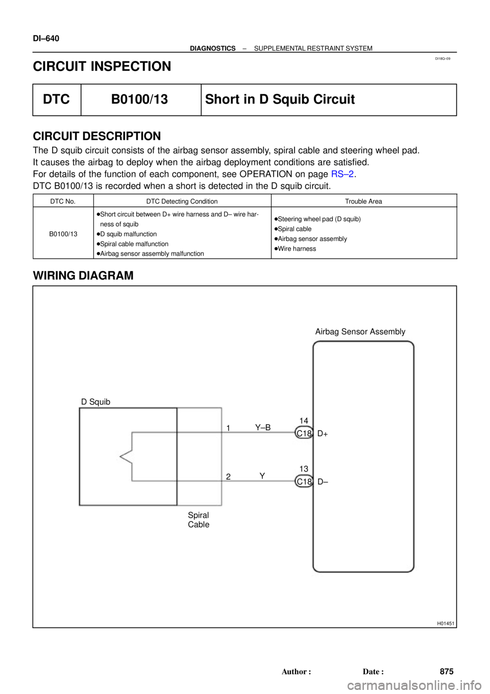
H01451
Y±B
D+ C1814Airbag Sensor Assembly
13
C18 D± Y 1
2
Spiral
Cable D Squib DI±640
± DIAGNOSTICSSUPPLEMENTAL RESTRAINT SYSTEM
875 Author�: Date�:
CIRCUIT INSPECTION
DTC B0100/13 Short in D Squib Circuit
CIRCUIT DESCRIPTION
The D squib circuit consists of the airbag sensor assembly, spiral cable and steering wheel pad.
It causes the airbag to deploy when the airbag deployment conditions are satisfied.
For details of the function of each component, see OPERATION on page RS±2.
DTC B0100/13 is recorded when a short is detected in the D squib circuit.
DTC No.DTC Detecting ConditionTrouble Area
B0100/13
�Short circuit between D+ wire harness and D± wire har-
ness of squib
�D squib malfunction
�Spiral cable malfunction
�Airbag sensor assembly malfunction�Steering wheel pad (D squib)
�Spiral cable
�Airbag sensor assembly
�Wire harness
WIRING DIAGRAM
Page 3061 of 4770
R14286H01001H01134
D SquibSpiral
Cable
Airbag
Sensor
Assembly
D+ u"
(±) (+)D±
± DIAGNOSTICSSUPPLEMENTAL RESTRAINT SYSTEM
DI±641
876 Author�: Date�:
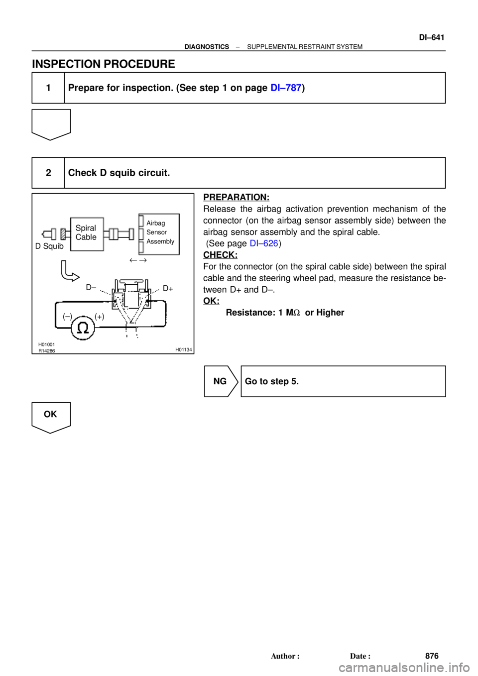
INSPECTION PROCEDURE
1 Prepare for inspection. (See step 1 on page DI±787)
2 Check D squib circuit.
PREPARATION:
Release the airbag activation prevention mechanism of the
connector (on the airbag sensor assembly side) between the
airbag sensor assembly and the spiral cable.
(See page DI±626)
CHECK:
For the connector (on the spiral cable side) between the spiral
cable and the steering wheel pad, measure the resistance be-
tween D+ and D±.
OK:
Resistance: 1 MW or Higher
NG Go to step 5.
OK
Page 3063 of 4770

AB0118
R13006AB0119FI1390
H01003H01136
D SquibSpiral
CableAirbag
Sensor
Assembly
E1 TcACC ON
or
DTC B0100/13
DLC1
" u
± DIAGNOSTICSSUPPLEMENTAL RESTRAINT SYSTEM
DI±643
878 Author�: Date�:
4 Check D squib.
PREPARATION:
(a) Turn ignition switch to LOCK.
(b) Disconnect negative (±) terminal cable from the battery,
and wait at least for 90 seconds.
(c) Connect the steering wheel pad connector.
(d) Connect negative (±) terminal cable to the battery, and
wait at least for 2 seconds.
CHECK:
(a) Turn ignition switch to LOCK, and wait at least for 20 se-
conds.
(b) Turn ignition switch to ACC or ON, and wait at least for 20
seconds.
(c) Clear DTC stored in memory.
(See page DI±626)
(d) Turn ignition switch to LOCK, and wait at least for 20 se-
conds.
(e) Turn ignition switch to ACC or ON, and wait at least for 20
seconds.
(f) Check DTC.
(See page DI±626)
OK:
DTC B0100/13 is not output.
HINT:
Codes other than code B0100/13 may be output at this time, but
they are not relevant to this check.
NG Replace steering wheel pad.
OK
From the results of the above inspection, the malfunctioning part can now be considered normal.
To make sure of this, use the simulation method to check.


(Squib) Side Airbag Sensor (LH)Side Airbag Sensor (RH)Side Airbag Assembly (RH)
(Squib)
Seat Belt
Pretensioner (RH)
Airbag Sensor
AssemblyFront Passenger Ai")

(Squib)
Seat Belt
Pretensioner (RH)
Side Airbag Sensor (RH)
Front Passenger Airbag
Assembly (Squib)
Spiral Cable
Steering Wheel
Pad (Squib)
No.1")
Steering Wheel Pad
(with Airbag)
Airbag Sensor AssemblyFront Passenger
Airbag Assembly
Side Airbag Assembly
(LH)
Side Airbag Sensor
Assembly (LH)
Seat")