Page 3632 of 4770

BO0MB±01
N20950
Instrument Panel ReinforcementNN
DD
No.2 Instrumental Panel Bracket
No.1 Instrumental Panel Bracket
No.2 Instrumental Panel Brace
QQH N
N
N
N
GG
NG
NOB
NN
Instrument Panel Brace Mount
No.1 Instrument
Panel BraceFront Pillar Garnish
Front Pillar
GarnishFront
Passenger
Airbag
Assembly
20 (200, 14)
No.2 Side Defroster Nozzle
Cowl Side Trim
Front Door Openin
g
Cover
Instrument Panel
C
Remote Control
Mirror Hole Base
Upper Column
CoverHazard Warning
Switch
Lower Finish
PlateGlove Compartment
Door Finish PlateFront Door
Inside Scuff Plate
FFF
FJ
Glove
Compartment
No.2 Lower
Panel A
A
Cluster Finish
Panel
Lower Column
Cover
Front Door
Opening
Cover
Cowl Side
TrimD
DD
D
D
F
AA
Lower Panel
InsertCoin
BoxCombination SwitchCombination
MeterRadio Assembly
Center Cluster
Finish Panel
A/C
Control Assembly
35 (360, 26)
Steering
Wheel
Pad Steering Wheel No.1 Lower
Panel
Front Door
Inside Scuff PlateFront Console
Box
Center Console
Upper PanelF
F
B
B
Rear Console
Box
N´m (kgf´cm, ft´lbf) : Specified torque BO±72
± BODYINSTRUMENT PANEL
2430 Author�: Date�:
2001 CAMRY (RM819U)
INSTRUMENT PANEL
COMPONENTS
Page 3635 of 4770
BO0MC±02
N20987
N21123
± BODYINSTRUMENT PANEL
BO±75
2433 Author�: Date�:
2001 CAMRY (RM819U)
REMOVAL
1. REMOVE THESE PARTS:
HINT:
Tape a screwdriver tip before use.
(a) Front door inside scuff plates
(b) Cowl side trims
(c) Front pillar garnishes
(d) Front door opening covers
(e) Lower finish plate
2. REMOVE STEERING WHEEL
(See page SR±11)
3. REMOVE STEERING COLUMN COVERS
(a) Remove the steering tilt handle.
(b) Remove the 3 screws, then the upper and lower column
covers.
4. REMOVE COMBINATION SWITCH
5. REMOVE No.1 LOWER PANEL
(a) Remove the 2 screws and hood lock release lever.
(b) Press on the sides of the coin box while pulling the coin
box outward, and remove the coin box.
(c) Remove the screw, bolt and the No.1 lower panel.
6. REMOVE LOWER PANEL INSERT
(a) Remove the 2 screws holding the DLC3 to the LH lower
panel.
(b) Remove the 4 bolts, and the panel.
7. REMOVE No.2 LOWER COVER
Page 3682 of 4770

W02655
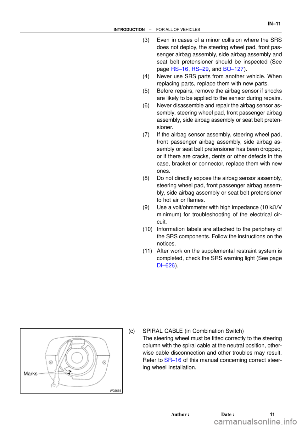
Marks
± INTRODUCTIONFOR ALL OF VEHICLES
IN±11
11 Author�: Date�:
(3) Even in cases of a minor collision where the SRS
does not deploy, the steering wheel pad, front pas-
senger airbag assembly, side airbag assembly and
seat belt pretensioner should be inspected (See
page RS±16, RS±29, and BO±127).
(4) Never use SRS parts from another vehicle. When
replacing parts, replace them with new parts.
(5) Before repairs, remove the airbag sensor if shocks
are likely to be applied to the sensor during repairs.
(6) Never disassemble and repair the airbag sensor as-
sembly, steering wheel pad, front passenger airbag
assembly, side airbag assembly or seat belt preten-
sioner.
(7) If the airbag sensor assembly, steering wheel pad,
front passenger airbag assembly, side airbag as-
sembly or seat belt pretensioner has been dropped,
or if there are cracks, dents or other defects in the
case, bracket or connector, replace them with new
ones.
(8) Do not directly expose the airbag sensor assembly,
steering wheel pad, front passenger airbag assem-
bly, side airbag assembly or seat belt pretensioner
to hot air or flames.
(9) Use a volt/ohmmeter with high impedance (10 kW/V
minimum) for troubleshooting of the electrical cir-
cuit.
(10) Information labels are attached to the periphery of
the SRS components. Follow the instructions on the
notices.
(11) After work on the supplemental restraint system is
completed, check the SRS warning light (See page
DI±626).
(c) SPIRAL CABLE (in Combination Switch)
The steering wheel must be fitted correctly to the steering
column with the spiral cable at the neutral position, other-
wise cable disconnection and other troubles may result.
Refer to SR±16 of this manual concerning correct steer-
ing wheel installation.
Page 3683 of 4770

Z13953
Example:CorrectWrong
Z13950
Example: IN±12
± INTRODUCTIONFOR ALL OF VEHICLES
12 Author�: Date�:
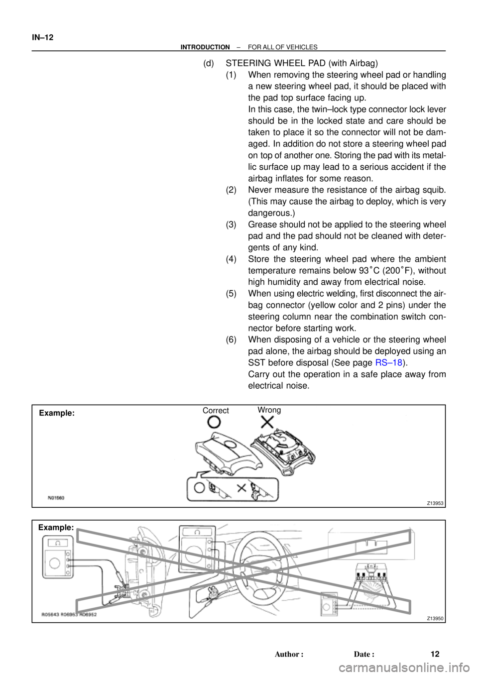
(d) STEERING WHEEL PAD (with Airbag)
(1) When removing the steering wheel pad or handling
a new steering wheel pad, it should be placed with
the pad top surface facing up.
In this case, the twin±lock type connector lock lever
should be in the locked state and care should be
taken to place it so the connector will not be dam-
aged. In addition do not store a steering wheel pad
on top of another one. Storing the pad with its metal-
lic surface up may lead to a serious accident if the
airbag inflates for some reason.
(2) Never measure the resistance of the airbag squib.
(This may cause the airbag to deploy, which is very
dangerous.)
(3) Grease should not be applied to the steering wheel
pad and the pad should not be cleaned with deter-
gents of any kind.
(4) Store the steering wheel pad where the ambient
temperature remains below 93°C (200°F), without
high humidity and away from electrical noise.
(5) When using electric welding, first disconnect the air-
bag connector (yellow color and 2 pins) under the
steering column near the combination switch con-
nector before starting work.
(6) When disposing of a vehicle or the steering wheel
pad alone, the airbag should be deployed using an
SST before disposal (See page RS±18).
Carry out the operation in a safe place away from
electrical noise.
Page 3689 of 4770

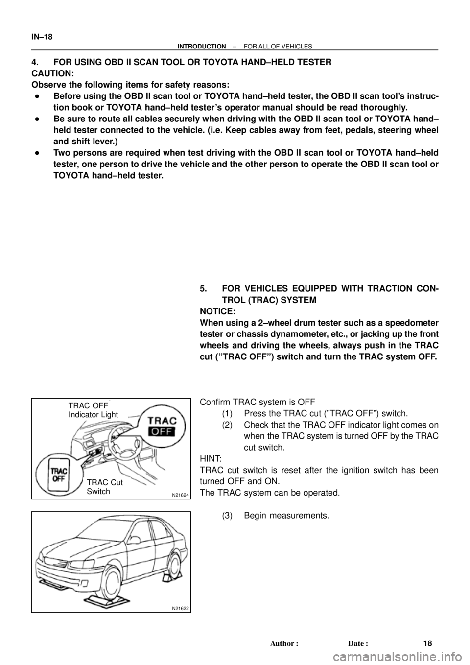
N21624
TRAC OFF
Indicator Light
TRAC Cut
Switch
N21622
IN±18
± INTRODUCTIONFOR ALL OF VEHICLES
18 Author�: Date�:
4. FOR USING OBD II SCAN TOOL OR TOYOTA HAND±HELD TESTER
CAUTION:
Observe the following items for safety reasons:
�Before using the OBD II scan tool or TOYOTA hand±held tester, the OBD II scan tool's instruc-
tion book or TOYOTA hand±held tester's operator manual should be read thoroughly.
�Be sure to route all cables securely when driving with the OBD II scan tool or TOYOTA hand±
held tester connected to the vehicle. (i.e. Keep cables away from feet, pedals, steering wheel
and shift lever.)
�Two persons are required when test driving with the OBD II scan tool or TOYOTA hand±held
tester, one person to drive the vehicle and the other person to operate the OBD II scan tool or
TOYOTA hand±held tester.
5. FOR VEHICLES EQUIPPED WITH TRACTION CON-
TROL (TRAC) SYSTEM
NOTICE:
When using a 2±wheel drum tester such as a speedometer
tester or chassis dynamometer, etc., or jacking up the front
wheels and driving the wheels, always push in the TRAC
cut (ºTRAC OFFº) switch and turn the TRAC system OFF.
Confirm TRAC system is OFF
(1) Press the TRAC cut (ºTRAC OFFº) switch.
(2) Check that the TRAC OFF indicator light comes on
when the TRAC system is turned OFF by the TRAC
cut switch.
HINT:
TRAC cut switch is reset after the ignition switch has been
turned OFF and ON.
The TRAC system can be operated.
(3) Begin measurements.
Page 3710 of 4770

± INTRODUCTIONTERMS
IN±39
39 Author�: Date�:
OHVOverhead Valve
OPTOption
O/SOversize
P & BVProportioning And Bypass Valve
PCSPower Control System
PCVPositive Crankcase Ventilation
PKBParking Brake
PPSProgressive Power Steering
PSPower Steering
PTOPower Take±Off
R & PRack And Pinion
R/BRelay Block
RBSRecirculating Ball Type Steering
R/FReinforcement
RFSRigid Front Suspension
RRSRigid Rear Suspension
RHRight±Hand
RHDRight±Hand Drive
RLYRelay
ROMRead Only Memory
RrRear
RRRear±Engine Rear±Wheel Drive
RWDRear±Wheel Drive
SDNSedan
SENSensor
SICSStarting Injection Control System
SOCState Of Charge
SOHCSingle Overhead Camshaft
SPECSpecification
SPISingle Point Injection
SRSSupplemental Restraint System
SSMSpecial Service Materials
SSTSpecial Service Tools
STDStandard
STJCold±Start Fuel Injection
SWSwitch
SYSSystem
T/ATransaxle
TACHTachometer
TBIThrottle Body Electronic Fuel Injection
TCTurbocharger
TCCSTOYOTA Computer±Controlled System
TCVTiming Control Valve
TDCTop Dead Center
TEMP.Temperature
TEMSTOYOTA Electronic Modulated Suspension
Page 3711 of 4770
IN±40
± INTRODUCTIONTERMS
40 Author�: Date�:
TISTotal Information System For Vehicle Development
T/MTransmission
TMCTOYOTA Motor Corporation
TMMKTOYOTA Motor Manufacturing Kentucky, Inc.
TRACTraction Control System
TURBOTurbocharge
U/DUnderdrive
U/SUndersize
VCVVacuum Control Valve
VENTVentilator
VINVehicle Identification Number
VPSVariable Power Steering
VSCVehicle Skid Control Vehicle Stability Control
VSVVacuum Switching Valve
VTVVacuum Transmitting Valve
w/With
WGNWagon
W/HWire Harness
w/oWithout
1stFirst
2ndSecond
2WDTwo Wheel Drive Vehicle (4x2)
4WDFour Wheel Drive Vehicle (4x4)
Page 3752 of 4770

MA002±11
MA±2
± MAINTENANCEINSIDE VEHICLE
45 Author�: Date�:
INSIDE VEHICLE
GENERAL MAINTENANCE
These are maintenance and inspection items which are considered to be the owner's responsibility.
They can be done by the owner or they can have them done at a service shop.
These items include those which should be checked on a daily basis, those which, in most cases, do not
require (special) tools and those which are considered to be reasonable for the owner to do.
Items and procedures for general maintenance are as follows.
1. GENERAL NOTES
�Maintenance items may vary from country to country. Check the owner's manual supplement in which
the maintenance schedule is shown.
�Every service item in the periodic maintenance schedule must be performed.
�Periodic maintenance service must be performed according to whichever interval in the periodic main-
tenance schedule occurs first, the odometer reading (miles) or the time interval (months).
�Maintenance service after the last period should be performed at the same interval as before unless
otherwise noted.
�Failure to do even one item an cause the engine to run poorly and increase exhaust emissions.
2. LIGHTS
(a) Check that the headlights, stop lights, taillights, turn signal lights, and other lights are all working.
(b) Check the headlight aim.
3. WARNING LIGHTS AND BUZZERS
Check that all warning lights and buzzers function properly.
4. HORN
Check that it is working.
5. WINDSHIELD GLASS
Check for scratches, pits or abrasions.
6. WINDSHIELD WIPER AND WASHER
(a) Check operation of the wipers and washer.
(b) Check that the wipers do not streak.
7. WINDSHIELD DEFROSTER
Check that air comes out from the defroster outlet when operating the heater or air conditioner.
8. REAR VIEW MIRROR
Check that it is mounted securely.
9. SUN VISORS
Check that they move freely and are mounted securely.
10. STEERING WHEEL
Check that it has the specified freeplay. Be alert for changes in steering condition, such as hard steering,
excessive freeplay or strange noises.
11. SEATS
(a) Check that the seat adjusters operate smoothly.
(b) Check that all latches lock securely in any position.
(c) Check that the head restraints move up and down smoothly and that the locks hold securely in any
latch position.
(d) For fold±down seat backs, check that the latches lock securely.
12. SEAT BELTS
(a) Check that the seat belt system such as the buckles, retractors and anchors operate properly and
smoothly.
(b) Check that the belt webbing is not cut, frayed, worn or damaged.