2000 TOYOTA CAMRY turn signal
[x] Cancel search: turn signalPage 1429 of 4770
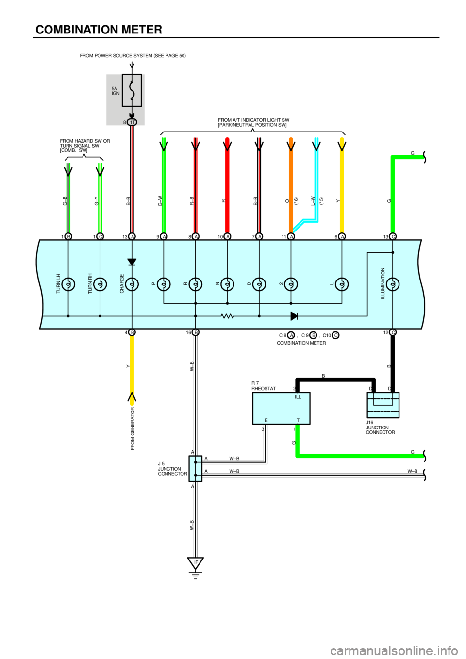
COMBINATION METER
5A
IGN
1T 8 FROM POWER SOURCE SYSTEM (
SEE PAGE 50)
B 1C1A13 A9A8A10 A7A6C13
B 4B16C 12
IFW±B
W±BG
W±BG
B
G±B
G±Y
B±R
G±W
R±B
R
B±R
O
Y
G Y
W± B W±B
G
B
A2DD
A31
A
AETILL FROM HAZARD SW OR
TURN SIGNAL SW
[COMB. SW]FROM A/T INDICATOR LIGHT S W
[PARK/NEUTRAL POSITION SW]FROM GE NERATORTURN LH
TURN RH
CHA RGE
P
R
N
D
2
L
ILLUMINATION
JUNCTION
CONNECTOR J16 RHEOSTAT R 7
JUNCTION
CONNE CTOR J 5C 8
COMBINATION METERB A, C 9 C, C10 A 11
L±W
(
*5) (
*6)
Page 1442 of 4770

1. HEATER BLOWER MOTOR OPERATION
Current is applied at all times through HTR fuse to TERMINAL 1 of the HTR relay. When the ignition SW is turned on,
current flows through the HEATER fuse to TERMINAL 5 of the HTR relay to TERMINAL 3 to TERMINAL HR of the A/C
control assembly. At the same time, current also flows from HEATER fuse to TERMINAL IG+ of the A/C control assembly.
*Low speed operation
When the blower SW (A/C control assembly) is pushed to LOW SPEED position, the current to TERMINAL HR of the
A/C control assembly flows to TERMINAL GND of the A/C control assembly to GROUND and turns the HTR relay on.
As a result, the current to TERMINAL 1 of the HTR relay flows to TERMINAL 2 of the relay to TERMINAL 2 of the
blower motor to TERMINAL 1 to TERMINAL 2 of the blower resistor to TERMINAL 6 to GROUND and causes the
blower motor to rotate at low speed.
*High speed operation
When the blower SW (A/C control assembly) is pushed to HIGH SPEED position, the current to TERMINAL HR of the
A/C control assembly flows to TERMINAL GND of the A/C control assembly to GROUND and turns the HTR relay on.
As a result, the current to TERMINAL 1 of the HTR relay flows to TERMINAL 2 to TERMINAL 2 of the blower motor to
TERMINAL 1 to TERMINAL 4 of the A/C blower motor linear controller to TERMINAL 2 to TERMINAL BLW of the A/C
control assembly (Which is activated when the blower SW is pushed to high speed position) to TERMINAL GND to
GROUND without passing through the blower resistor, causing the blower motor to rotate at high speed.
2. AIR INLET CONTROL SERVO MOTOR OPERATION
(Switching from FRESH to RECIRC)
With the ignition SW turned on, the current flows from HEATER fuse to TERMINAL IG+ of the A/C control assembly to
TERMINAL AIR to TERMINAL 7 of the air inlet control servo motor to TERMINAL 6 to TERMINAL AIF of the A/C control
assembly to TERMINAL GND to GROUND, the motor rotates and the damper moves to the RECIRC side. when the
damper operates with the A/C SW at RECIRC position, the damper position signal is input from TERMINAL 5 of the servo
motor to TERMINAL TPI of the A/C control assembly. As a result, current to the servo motor circuit is cut off by the A/C
control assembly, so the damper stops at that position.
(Switching from RECIRC to FRESH)
With the ignition SW turned on, when the RECIRC/FRESH SW is switched to the FRESH side, the current flows from
TERMINAL IG+ of the A/C control assembly to TERMINAL AIF to TERMINAL 6 of the air inlet control servo motor to
TERMINAL 7 to TERMINAL AIR of the A/C control assembly to TERMINAL GND to GROUND, The motor rotates and the
damper stops at that position.
3. AIR VENT MODE CONTROL SERVO MOTOR OPERATION
When the ignition SW turned on, the current flows from HEATER fuse to TERMINAL IG+ of the A/C control assembly.
(Switching from DEF to FACE)
The current flows from TERMINAL FACE of the A/C control assembly to TERMINAL 1 of the air vent mode control servo
motor to TERMINAL 5 to TERMINAL DEF of the A/C control assembly to TERMINAL GND to GROUND. The motor rotates
and the damper moves to the FACE side. When the damper operates with the A/C SW at FACE position, the damper
position signal is input from TERMINAL 5 of the servo motor to the TERMINAL DEF of the A/C control assembly. As a
result, current to the servo motor circuit is cut off by the A/C control assembly, so the damper stops at that position.
(Switching from FACE to DEF)
The current flows from TERMINAL DEF of the A/C control assembly to TERMINAL 5 of the air vent control servo motor to
TERMINAL 1 to TERMINAL FACE of the A/C control assembly to TERMINAL GND to GROUND, the motor rotates and the
damper stops at that position.
4. AIR MIX CONTROL SERVO MOTOR OPERATION
When the temperature control SW (A/C control assembly) is turned to the ºCOOLº side the current flows from TERMINAL
AMC of the A/C control assembly to TERMINAL 1 of the air mix control servo motor to motor to TERMINAL 2 to
TERMINAL AMH of the A/C control assembly to GROUND and the motor rotates. The damper opening angle at this time
is input from TERMINAL 3 of the servo motor to TERMINAL TP of the A/C control assembly, this is used to determine the
DAMPER STOP position and maintain the set temperature.
When the temperature control SW (A/C control assembly) is turned to the ºHOTº side, the current flows from servo motor
to TERMINAL AMH of the A/C control assembly to TERMINAL 2 of the air mix control servo motor to motor to TERMINAL
1 to TERMINAL AMC of the A/C control assembly, rotating the motor in reverse and switching the damper from ºCOOLº to
ºHOTº side.
SYSTEM OUTLINE
Page 1443 of 4770
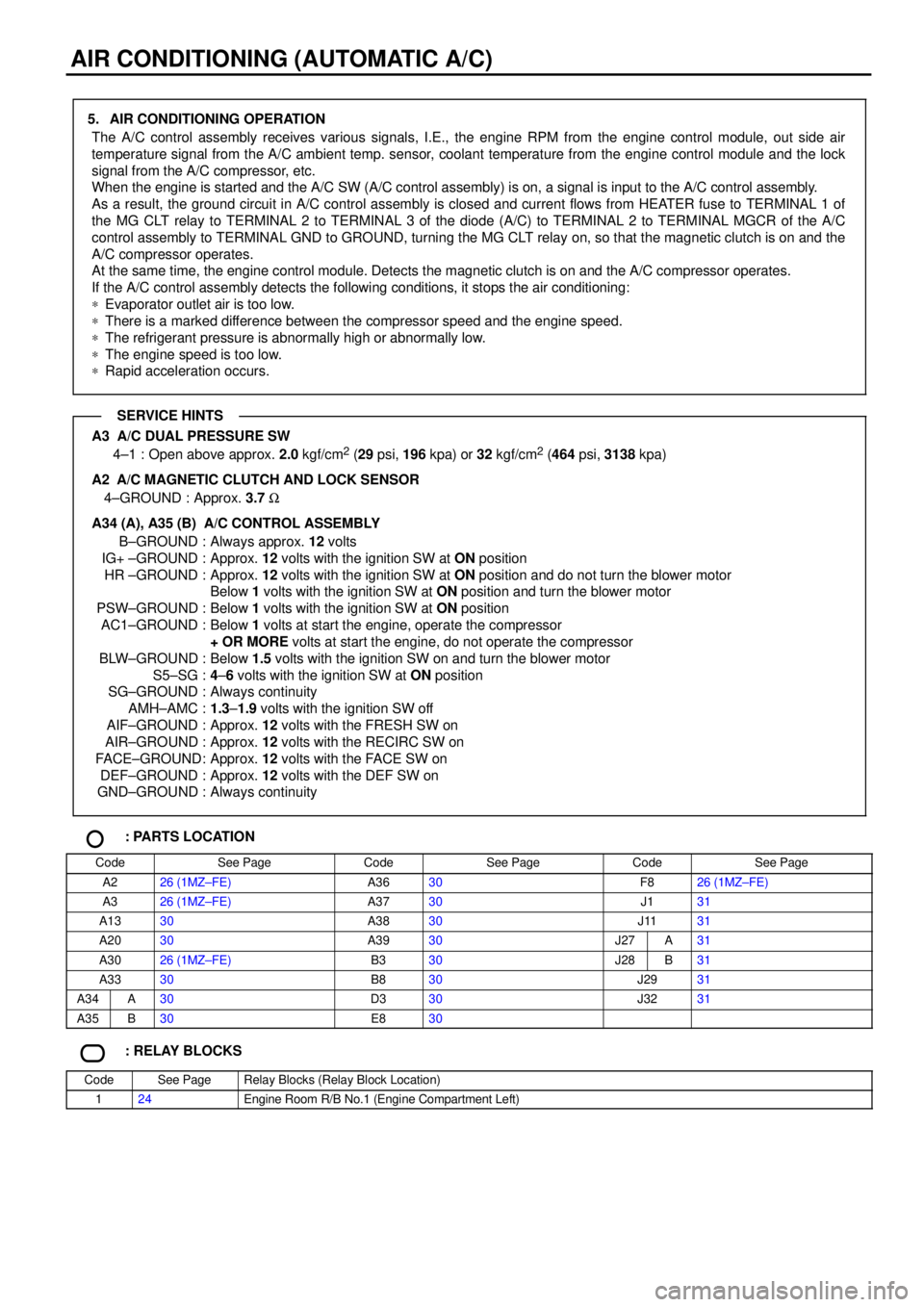
AIR CONDITIONING (AUTOMATIC A/C)
5. AIR CONDITIONING OPERATION
The A/C control assembly receives various signals, I.E., the engine RPM from the engine control module, out side air
temperature signal from the A/C ambient temp. sensor, coolant temperature from the engine control module and the lock
signal from the A/C compressor, etc.
When the engine is started and the A/C SW (A/C control assembly) is on, a signal is input to the A/C control assembly.
As a result, the ground circuit in A/C control assembly is closed and current flows from HEATER fuse to TERMINAL 1 of
the MG CLT relay to TERMINAL 2 to TERMINAL 3 of the diode (A/C) to TERMINAL 2 to TERMINAL MGCR of the A/C
control assembly to TERMINAL GND to GROUND, turning the MG CLT relay on, so that the magnetic clutch is on and the
A/C compressor operates.
At the same time, the engine control module. Detects the magnetic clutch is on and the A/C compressor operates.
If the A/C control assembly detects the following conditions, it stops the air conditioning:
*Evaporator outlet air is too low.
*There is a marked difference between the compressor speed and the engine speed.
*The refrigerant pressure is abnormally high or abnormally low.
*The engine speed is too low.
*Rapid acceleration occurs.
A3 A/C DUAL PRESSURE SW
4±1 : Open above approx. 2.0 kgf/cm2 (29 psi, 196 kpa) or 32 kgf/cm2 (464 psi, 3138 kpa)
A2
A/C MAGNETIC CLUTCH AND LOCK SENSOR
4±GROUND : Approx. 3.7 W
A34 (A), A35 (B) A/C CONTROL ASSEMBLY
B±GROUND : Always approx. 12 volts
IG+ ±GROUND : Approx. 12 volts with the ignition SW at ON position
HR ±GROUND : Approx. 12 volts with the ignition SW at ON position and do not turn the blower motor
Below 1 volts with the ignition SW at ON position and turn the blower motor
PSW±GROUND : Below 1 volts with the ignition SW at ON position
AC1±GROUND : Below 1 volts at start the engine, operate the compressor
+ OR MORE volts at start the engine, do not operate the compressor
BLW±GROUND : Below 1.5 volts with the ignition SW on and turn the blower motor
S5±SG :4±6 volts with the ignition SW at ON position
SG±GROUND : Always continuity
AMH±AMC :1.3±1.9 volts with the ignition SW off
AIF±GROUND : Approx. 12 volts with the FRESH SW on
AIR±GROUND : Approx. 12 volts with the RECIRC SW on
FACE±GROUND: Approx. 12 volts with the FACE SW on
DEF±GROUND : Approx. 12 volts with the DEF SW on
GND±GROUND : Always continuity
: PARTS LOCATION
CodeSee PageCodeSee PageCodeSee Page
A226 (1MZ±FE)A3630F826 (1MZ±FE)
A326 (1MZ±FE)A3730J131
A1330A3830J1131
A2030A3930J27A31
A3026 (1MZ±FE)B330J28B31
A3330B830J2931
A34A30D330J3231
A35B30E830
: RELAY BLOCKS
CodeSee PageRelay Blocks (Relay Block Location)
124Engine Room R/B No.1 (Engine Compartment Left)
SERVICE HINTS
Page 1450 of 4770
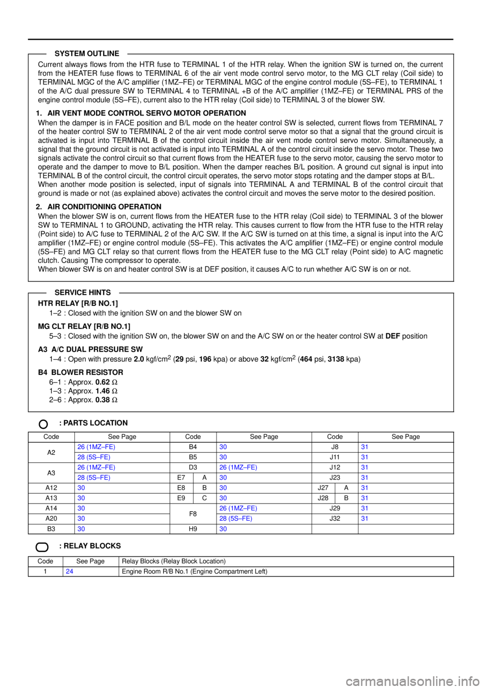
Current always flows from the HTR fuse to TERMINAL 1 of the HTR relay. When the ignition SW is turned on, the current
from the HEATER fuse flows to TERMINAL 6 of the air vent mode control servo motor, to the MG CLT relay (Coil side) to
TERMINAL MGC of the A/C amplifier (1MZ±FE) or TERMINAL MGC of the engine control module (5S±FE), to TERMINAL 1
of the A/C dual pressure SW to TERMINAL 4 to TERMINAL +B of the A/C amplifier (1MZ±FE) or TERMINAL PRS of the
engine control module (5S±FE), current also to the HTR relay (Coil side) to TERMINAL 3 of the blower SW.
1. AIR VENT MODE CONTROL SERVO MOTOR OPERATION
When the damper is in FACE position and B/L mode on the heater control SW is selected, current flows from TERMINAL 7
of the heater control SW to TERMINAL 2 of the air vent mode control serve motor so that a signal that the ground circuit is
activated is input into TERMINAL B of the control circuit inside the air vent mode control servo motor. Simultaneously, a
signal that the ground circuit is not activated is input into TERMINAL A of the control circuit inside the servo motor. These two
signals activate the control circuit so that current flows from the HEATER fuse to the servo motor, causing the servo motor to
operate and the damper to move to B/L position. When the damper reaches B/L position. A ground cut signal is input into
TERMINAL B of the control circuit, the control circuit operates, the servo motor stops rotating and the damper stops at B/L.
When another mode position is selected, input of signals into TERMINAL A and TERMINAL B of the control circuit that
ground is made or not (as explained above) activates the control circuit and moves the serve motor to the desired position.
2. AIR CONDITIONING OPERATION
When the blower SW is on, current flows from the HEATER fuse to the HTR relay (Coil side) to TERMINAL 3 of the blower
SW to TERMINAL 1 to GROUND, activating the HTR relay. This causes current to flow from the HTR fuse to the HTR relay
(Point side) to A/C fuse to TERMINAL 2 of the A/C SW. If the A/C SW is turned on at this time, a signal is input into the A/C
amplifier (1MZ±FE) or engine control module (5S±FE). This activates the A/C amplifier (1MZ±FE) or engine control module
(5S±FE) and MG CLT relay so that current flows from the HEATER fuse to the MG CLT relay (Point side) to A/C magnetic
clutch. Causing The compressor to operate.
When blower SW is on and heater control SW is at DEF position, it causes A/C to run whether A/C SW is on or not.
HTR RELAY [R/B NO.1]
1±2 : Closed with the ignition SW on and the blower SW on
MG CLT RELAY [R/B NO.1]
5±3 : Closed with the ignition SW on, the blower SW on and the A/C SW on or the heater control SW at DEF position
A3 A/C DUAL PRESSURE SW
1±4 : Open with pressure 2.0 kgf/cm
2 (29 psi, 196 kpa) or above 32 kgf/cm2 (464 psi, 3138 kpa)
B4
BLOWER RESISTOR
6±1 : Approx. 0.62 W
1±3 : Approx. 1.46 W
2±6 : Approx. 0.38 W
: PARTS LOCATION
CodeSee PageCodeSee PageCodeSee Page
A226 (1MZ±FE)B430J831A228 (5S±FE)B530J1131
A326 (1MZ±FE)D326 (1MZ±FE)J1231A328 (5S±FE)E7A30J2331
A1230E8B30J27A31
A1330E9C30J28B31
A1430F826 (1MZ±FE)J2931
A2030F828 (5S±FE)J3231
B330H930
: RELAY BLOCKS
CodeSee PageRelay Blocks (Relay Block Location)
124Engine Room R/B No.1 (Engine Compartment Left)
SYSTEM OUTLINE
SERVICE HINTS
Page 1453 of 4770
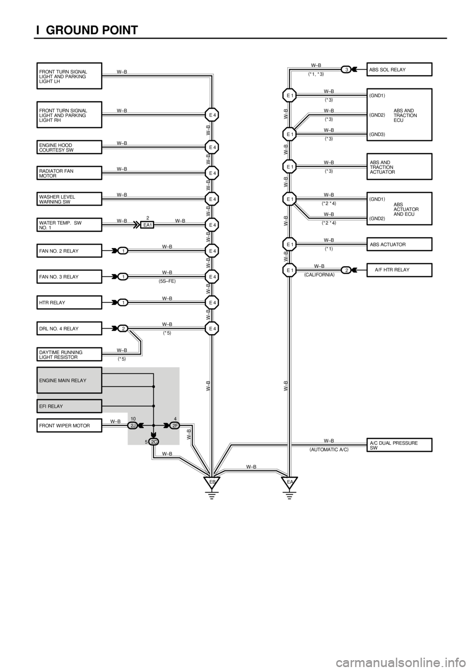
I GROUND POINT
FRONT TURN SIGNAL
LIGHT AND PARKING
LIGHT LH
FRONT TURN SIGNAL
LIGHT AND PARKING
LIGHT RH
ENGINE HOOD
COURTESY SW
RADIATOR FAN
MOTOR
WASHER LEVEL
WARNING SW
WATER TEMP. SW
NO. 1
FAN NO. 2 RELAYABS SOL RELAY
ABS AND
TRACTION
ECU (
GND2)
(
GND3)
(
GND1)
(
GND2)
FAN NO. 3 RELAY
HTR RELAY
DRL NO. 4 RELAY
ENGINE MAIN RELAY
EFI RELAY
FRONT WIPER MOTOR(
GND1)
ABS AND
TRACTION
ACTUATOR
ABS
ACTUATOR
AND ECU
ABS ACTUATOR
1
1
1
2EA12
E 4 E 4
E 4
E 4
E 4
E 4
E 4
E 4
E 4
2J 10
2F4
2C 5
EB3
E 1
E 1
E 1
E 1
E 1
EA W±B W±B W±B
W±B W±B W±B
W± B
W±B
W±B
W±B
W±BW±B
W±B
W±B
W±B
W±B
W±B
W±B
W±B W± B W±B W±B W± B W±B W±B W±B W±B
W±B
W± B W± B W±B W±B W±B
W± B
(
5S±FE)(
*1, *3)
(
*3)
(
*3)
(
*3)
(
*3)
(
*2 *4)
(
*2 *4)
(
*1)
(
*5)
W±B
W±B DAYTIME RUNNING
LIGHT RESISTORW±B
(
*5)
W±BE 1 2W±B
(
CALIFORNIA)A/F HTR RELAY
W±B
A/C DUAL PRESSURE
SW W±B
(
AUTOMATIC A/C)
Page 1455 of 4770
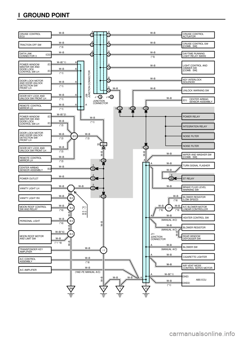
I GROUND POINT
CRUISE CONTROL
ECU
TRACTI ON OFF SW
DATA LINK
CONNECTOR 3
POWER RELAY
INTEGRA TION RELAY
NOISE FILTER POWER WINDOW
MASTER SW AND
DOOR LOCK
CONTROL SW LHCRUISE CONTROL
ACTUATOR
CRUISE CONTROL S W
[COMB. SW]
LIGHT CONTROL AND
DIMMER SW
[COMB. SW]
KEY INTERLOCK
SOLENOID
UNLOCK WARNING SW
CENTER AIRBAG
SENSOR ASSEMBLY
WIPER AND WASHER SW
[COMB. SW]
BRAKE FLUID LEVEL
WARNING SW
A/C AMPLIFIERHEATER CONTROL SW
AIR VENT MODE
CONTROL SERVO MOTOR BLOWER SW BLOWER RESISTOR
REAR WINDOW
DEFOGGER SW
CIGARETTE LIGHTER TURN SIGNAL FLASHE R
ST RELAY DOOR LOCK MOTOR
AND DOOR UNLOCK
DETECTION SW
FRONT L H
DOOR KEY LOCK AND
UNLOCK SW FRONT LH
REMOTE CONTROL
MIRROR LH
CENTER AIRB AG
SENSOR ASSEMBLY
POWER OUTLET
VANITY LIGHT LH
VANITY LIGHT RH
MOON ROOF CONTROL
SW AND RELAY
PERSONAL LIGHT
MOON ROOF MOTOR
AND LIMIT SWA A
A A
A A
A A
A A B A
B A
B A
1J 81M31N1
A A
A
A
A
A
A
A
A A A
1N3
1V4
1F31G 7
1V 3IE1 20
IG IE B 2
B 2
B 3
B 2
BM IIANOISE FILTER W±B
W±B
W±B
W±B W±B W±B W±B W±B W±B
W±B
W±B W±B
W±B W±B(
*2)
W±B
W±B
W±B
W±B
W±B
W±B
W±B W±B
W±B
W±B
W±B
W± B(
*6)
W± B W± B
W±B W± B W±B W± B
W± B
JUNCTION CONNECTOR J38
JUNCTION
CONNECTOR J1 1
W±BW±B
W± B (
*3)
B 3 : * 6
B 2 : * 7
(
E)
(
E) (
CG)
(
E1)
(
E2)
W±B
(
*1 *6)
W±B
DAYTIME RUNNING
LIGHT RELAY (
MAIN) A A
W±B
(
*5)
(
1 MZ± FE MANUAL A/ C)2K9
I 1 TRANSPONDER KEY
AMPLIFIERW± B
W±B
W±B
W±B W±B W±B W±B W±B 1J 7
W±B
W± B
W±B
J 7
J UNCTION
CONNECTORB A, J 8 POWER WINDOW
MASTER SW AND
DOOR LOCK
CONTROL SW LH
DOOR LOCK MOTOR
AND DOOR UNLOCK
DETECTION SW
FRONT L H
DOOR KEY LOCK AND
UNLOCK SW FRONT LH
REMOTE CONTROL
MIRROR LHW±B(
*1)
W±B
W±B
W±B
W±B (
E)
(
E)
B13 (
*1)
(
*1)
(
*1) (
*1)
(
*2)
(
*2)
(
*2)
(
*2)(
*1)
W± B
(
*2)
A/C CONTROL
ASSEMBLYW± B
(
*9) (
*6)
(
*6)(
MANU AL A/ C)
(
MANU AL A/ C)
(
MANU AL A/ C)BLOWER RESISTOR
(
LOW SPEED)
A/C BLOWER MOTOR
LINEAR CONTROLLER I 7 W±B W±BW± B
(
*9)(
*9) (
*9)
ABS ECU (
GND)
(
GND2) AW±B(
*1)
W±B
(
*1)
Page 1463 of 4770

SYSTEM INDEX
J OVERALL ELECTRICAL WIRING DIAGRAM
SYSTEMS LOCATION SYSTEMS LOCATION
ABS
TMC Made 19±2. . . . . . . . . . . . . . . . . . . . . . . . . . . . . . . . . . . . . . . . . . . . .
TMMK Made 20±2. . . . . . . . . . . . . . . . . . . . . . . . . . . . . . . . . . . . . . . . . . .
ABS and Traction Control 18±2. . . . . . . . . . . . . . . . . . . . . . . . . . . . . . . . . . .
Air Conditioning
Automatic A/C 29±2. . . . . . . . . . . . . . . . . . . . . . . . . . . . . . . . . . . . . . . . . .
Manual A/C 27±2. . . . . . . . . . . . . . . . . . . . . . . . . . . . . . . . . . . . . . . . . . . .
Auto Antenna 24±2. . . . . . . . . . . . . . . . . . . . . . . . . . . . . . . . . . . . . . . . . . . . .
Back±Up Light 8±4. . . . . . . . . . . . . . . . . . . . . . . . . . . . . . . . . . . . . . . . . . . . . .
Charging 1±4. . . . . . . . . . . . . . . . . . . . . . . . . . . . . . . . . . . . . . . . . . . . . . . . . . .
Cigarette Lighter and Clock 16±4. . . . . . . . . . . . . . . . . . . . . . . . . . . . . . . . .
Combination Meter 25±2. . . . . . . . . . . . . . . . . . . . . . . . . . . . . . . . . . . . . . . .
Cruise Control 17±2. . . . . . . . . . . . . . . . . . . . . . . . . . . . . . . . . . . . . . . . . . . . .
Door Lock Control 14±2. . . . . . . . . . . . . . . . . . . . . . . . . . . . . . . . . . . . . . . . .
Electronically Controlled Transmission and A/T Indicator
1MZ±FE 4±2. . . . . . . . . . . . . . . . . . . . . . . . . . . . . . . . . . . . . . . . . . . . . . . . .
5S±FE 5±2. . . . . . . . . . . . . . . . . . . . . . . . . . . . . . . . . . . . . . . . . . . . . . . . . .
Engine Control and Engine Immobiliser System
1MZ±FE 2±2. . . . . . . . . . . . . . . . . . . . . . . . . . . . . . . . . . . . . . . . . . . . . . . . .
5S±FE 3±2. . . . . . . . . . . . . . . . . . . . . . . . . . . . . . . . . . . . . . . . . . . . . . . . . .
Headlight
w/ Daytime Running Light 7±2. . . . . . . . . . . . . . . . . . . . . . . . . . . . . . . . . .
w/o Daytime Running Light 6±2. . . . . . . . . . . . . . . . . . . . . . . . . . . . . . . . .
Horn 21±4. . . . . . . . . . . . . . . . . . . . . . . . . . . . . . . . . . . . . . . . . . . . . . . . . . . . .
Illumination 10±2. . . . . . . . . . . . . . . . . . . . . . . . . . . . . . . . . . . . . . . . . . . . . . .
Interior Light 9±3. . . . . . . . . . . . . . . . . . . . . . . . . . . . . . . . . . . . . . . . . . . . . . . .
Key Reminder and Seat Belt Warning 21±3. . . . . . . . . . . . . . . . . . . . . . . . Light Auto Turn Off 9±1. . . . . . . . . . . . . . . . . . . . . . . . . . . . . . . . . . . . . . . . . .
Moon Roof 21±2. . . . . . . . . . . . . . . . . . . . . . . . . . . . . . . . . . . . . . . . . . . . . . .
Power Outlet 16±3. . . . . . . . . . . . . . . . . . . . . . . . . . . . . . . . . . . . . . . . . . . . . .
Power Seat 22±2. . . . . . . . . . . . . . . . . . . . . . . . . . . . . . . . . . . . . . . . . . . . . . .
Power Source 1~29±1. . . . . . . . . . . . . . . . . . . . . . . . . . . . . . . . . . . . . . . . . . .
Power Window 13±2. . . . . . . . . . . . . . . . . . . . . . . . . . . . . . . . . . . . . . . . . . . .
Radiator Fan and Condenser Fan 26±3. . . . . . . . . . . . . . . . . . . . . . . . . . . .
Radio and Player
Built±In Type Amplifier 24±3. . . . . . . . . . . . . . . . . . . . . . . . . . . . . . . . . . .
Separate Type Amplifier 23±2. . . . . . . . . . . . . . . . . . . . . . . . . . . . . . . . .
Rear Window Defogger and Mirror Heater 26±2. . . . . . . . . . . . . . . . . . . .
Remote Control Mirror 12±4. . . . . . . . . . . . . . . . . . . . . . . . . . . . . . . . . . . . . .
Shift Lock 16±2. . . . . . . . . . . . . . . . . . . . . . . . . . . . . . . . . . . . . . . . . . . . . . . .
SRS 28±2. . . . . . . . . . . . . . . . . . . . . . . . . . . . . . . . . . . . . . . . . . . . . . . . . . . . .
Starting and Ignition 1±2. . . . . . . . . . . . . . . . . . . . . . . . . . . . . . . . . . . . . . . . . .
Stop Light 11±4. . . . . . . . . . . . . . . . . . . . . . . . . . . . . . . . . . . . . . . . . . . . . . . . .
Taillight 11±2. . . . . . . . . . . . . . . . . . . . . . . . . . . . . . . . . . . . . . . . . . . . . . . . . . . .
Theft Deterrent 15±2. . . . . . . . . . . . . . . . . . . . . . . . . . . . . . . . . . . . . . . . . . . .
Turn Signal and Hazard Warning Light 8±2. . . . . . . . . . . . . . . . . . . . . . . . . .
Wiper and Washer 12±2. . . . . . . . . . . . . . . . . . . . . . . . . . . . . . . . . . . . . . . . .
Wireless Door Lock Control 14±5. . . . . . . . . . . . . . . . . . . . . . . . . . . . . . . . .
Page 1476 of 4770
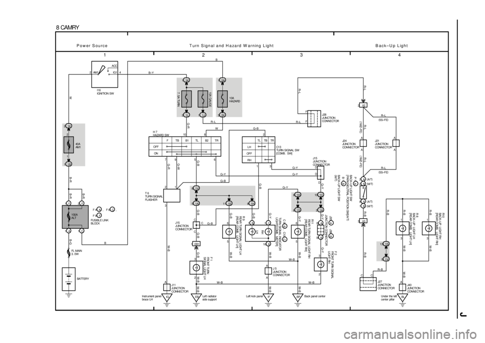
J
1
234
8 CAMRY
2ACC
IG1 AM1 4
40A
AM1 1K 2
1B 1
1F 2F
1A 1C
7. 5A TURN 10A GAUGE
10A
HAZARD
1L 21J12K3 1K 12A1
OFF
ONF TBB1TLB2TR
IGW
G±R10
G± R
1V 8
1A 51S11
1EB13 1
BL Under the left
center pillar1S 13
1V 5
2 3 BB BA1C 10 1H 6
1S 6
5 6
5 6
2 3
IF Left k ick panel
EBLeft r adiat or
side s uppor tBPBack panel c ent er 1H 8
3
CA
D
21
C
A
A A
D
D I16
IGNI TION SW
T 6
TURN SIGNAL
FL ASHER
J15
JUNCTION
CONNECTOR H 7
HAZARD SW
F 1
FRONT TURN
SIGNAL LIGHT LH R 9
REAR TURN SIGNAL LIGHT LH
[REAR COMB. LI GHT LH]R11
REAR TURN SIGNAL LIGHT RH
[REAR COMB. LIGHT RH]F 2
FRONT TURN SIGNAL
LI GHT RH
J15
JUNCTION
CONNE CTORJ24
JUNCTI ON
CONNE CTOR
R 8
BACK±UP LIGHT LH
[REAR COMB. LIGHT LH]
J 5
JUNCTION
CONNECTOR FUSIBLE LINK
BLOCK
JUNCTION CONNECTOR
79568 B±YB
BG±Y
G±BG± B
G±Y
G±Y
G± Y
W± B R±L
WB±RB±RB±R
B±G G±B G±B G±B W±BW± B
W±B G±B G±B G±YG±Y W±B W±B
W± B
LH RH R± L R± LR±B W±B
R±B R±B
G±Y
Power Source Turn Signal and Hazard W arning Light B ack±Up Light
G± W G±BG±Y
C
A
J11
JUNCTION
CONNECTORA
W± B
1A 2G±Y
3 1
R1 0
BACK± UP LI GHT RH
[REAR COMB. LIGHT RH]
W±B
W± B R±B
R±B
J40
JUNCTI ON
CONNE CTOR BATT ERY 100A
ALT
FL MAIN
3. 0W2
1 2
Ins tr ument panel
brace LHLH
OF F
RHTL TB TR
3 1
G±BC1 3
TURN SIGNAL SW
[COMB. SW]
G±B
II2 2
A A
J21
JUNCTION
CONNECTOR
2B 2A
8A
1BR± L
(
5S±FE)(
1MZ±FE)
R± L
(
5S±FE)
(
1 MZ± FE)
(
A/ T)
(
M/ T)
(
A/ T)
(
M/ T)
R±LR±LF
F
R± L
J28
JUNCTION
CONNECTOR
BACK±UP LIGHT SW
[ PARK/ NEUTRAL POSITION SW](
A/ T)
BACK±UP LIGHT SW
(
M/T)
1B 1C
16 B
TURN SI GNAL I NDICATOR
LIGHT[COMB. METER]
W± B
W±B W± B3II3
R± B
C C
J27
JUNCTI ON
CONNE CTOR , F 6 F 4 A C ,
F 9 F
C C 9 C10B, B J35 J36A, P 1 A
B 1 B