Page 1964 of 4770
BO0KW±01
H01709
H01710
H01711
H01712
± BODYFRONT BUMPER
BO±5
2353 Author�: Date�:
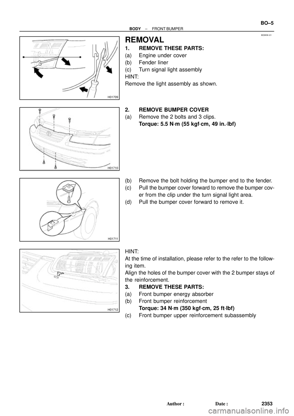
REMOVAL
1. REMOVE THESE PARTS:
(a) Engine under cover
(b) Fender liner
(c) Turn signal light assembly
HINT:
Remove the light assembly as shown.
2. REMOVE BUMPER COVER
(a) Remove the 2 bolts and 3 clips.
Torque: 5.5 N´m (55 kgf´cm, 49 in.´lbf)
(b) Remove the bolt holding the bumper end to the fender.
(c) Pull the bumper cover forward to remove the bumper cov-
er from the clip under the turn signal light area.
(d) Pull the bumper cover forward to remove it.
HINT:
At the time of installation, please refer to the refer to the follow-
ing item.
Align the holes of the bumper cover with the 2 bumper stays of
the reinforcement.
3. REMOVE THESE PARTS:
(a) Front bumper energy absorber
(b) Front bumper reinforcement
Torque: 34 N´m (350 kgf´cm, 25 ft´lbf)
(c) Front bumper upper reinforcement subassembly
Page 2098 of 4770
1. Integration Relay (I/P J/B No.1)
2. Light Control Switch
3. Wire HarnessBE±1")
BE±4
± BODY ELECTRICALBODY ELECTRICAL SYSTEM
2224 Author�: Date�:
Taillight does not light.
(Headlight does not light)1. Integration Relay (I/P J/B No.1)
2. Light Control Switch
3. Wire HarnessBE±14
BE±24
±
Taillight does not light.
(Headlight is normal)
1. TAIL Fuse (I/P J/B No.1)
2. Taillight Control Relay (I/P J/B No.1)
3. Integration Relay (I/P J/B No.1)
4. Light Control Switch
5. Wire Harness±
BE±24
BE±14
BE±24
±
Only one side light does not light.1. Bulb
2. Wire Harness±
±
Rear Combination light does not light.
1. Bulb
2. Light Failure Sensor
3. Wire Harness±
BE±37
±
ºAuto Turn±off Systemº does not operate.
1. GAUGE Fuse (I/P J/B No.1)
2. Integration Relay (I/P J/B No.1)
3. Door Courtesy Switch (Driver's)
4. Wire Harness±
BE±14
BE±24
±
*Terminal L of generator and parking brake switch
TURN SIGNAL AND HAZARD WARNING SYSTEM
SymptomSuspect AreaSee page
ºHazardº and ºTurnº do not light up.
1. Hazard Warning Switch
2. Turn Signal Flasher
3. Wire HarnessBE±30
BE±30
±
The flashing frequency is abnormal.
1. Bulb
2. Turn Signal Switch
3. Wire Harness±
BE±30
±
Hazard warning light does not light up.
(Turn is normal.)1. HORN Fuse (E/G Room J/B No.2)
2. Wire Harness±
±
Hazard warning light does not light up in one direction.1. Hazard Warning Switch
2. Wire HarnessBE±30
±
*1Turn signal does not light up.
1. Ignition Switch
2. TURN Fuse (I/P J/B No.1)
3. Turn Signal Switch
4. Wire HarnessBE±14
±
BE±30
±
*2Turn signal does not light up.
1. TURN Fuse (I/P J/B No.1)
2. Turn Signal Switch
3. Wire Harness±
BE±30
±
Turn signal does not light up in one direction.1. Turn Signal Switch
2. Wire HarnessBE±30
±
Only one bulb does not light up.1. Bulb
2. Wire Harness±
±
*1: Combination meter, wiper and washer do not operate.
*
2: Combination meter, wiper and washer are normal.
INTERIOR LIGHT SYSTEM
SymptomSuspect AreaSee page
ºIlluminated Entry Systemº does not operate.
1. Door Courtesy Switch
2. Integration Relay (I/P J/B No.1)
3. Wire HarnessBE±32
BE±14
±
Only one interior light does not light up.1. Bulb
2. Wire Harness±
±
Interior light does not light up (All).1. DOME Fuse (E/G Room J/B No.2)
2. Wire Harness±
±
Page 2101 of 4770

4. Wire Harness±")
± BODY ELECTRICALBODY ELECTRICAL SYSTEM
BE±7
2227 Author�: Date�:
Seat Belt warning light does not light up.
1. Bulb
2. Seat Belt Buckle Switch
3. Integration Relay (I/P J/B No.1)
4. Wire Harness±
BE±47
BE±47
±
Discharge warning light does not light up.
1. IGN Fuse (I/P J/B No.1)
2. Bulb
3. Wire Harness
4. Generator (5S±FE)
(1MZ±FE)±
±
±
CH±1
CH±1
Light Failure warning light does not light up.
1. Bulb
2. Light Failure Sensor
3. Bulb Check Relay
4. Wire Harness
5. Taillight system±
BE±37
BE±47
±
BE±24
Brake warning light does not light up.
1. Bulb
2. Parking Brake Switch
3. Brake Fluid Level Warning Switch
4. Bulb Check Relay
5. Meter Circuit Plate
6. Wire Harness±
BE±47
BE±47
BE±47
BE±46
±
SRS Warning light does not light up.
1. ECU±B Fuse (E/G Room J/B No.2)
2. Bulb
3. Airbag Sensor Assembly
4. Meter Circuit Plate
5. Wire Harness±
±
DI±626
BE±46
±
Open Door warning light does not light up.
1. DOME Fuse (E/G Room J/B No.2)
2. Bulb
3. Door Courtesy Switch
4. Meter Circuit Plate
5. Wire Harness±
±
BE±32
BE±46
±
Washer Level warning light does not light up.
1. Bulb
2. Washer Fluid Level Warning Switch
3. Meter Circuit Plate
4. Wire Harness±
BE±47
BE±46
±
COMBINATION METER
INDICATOR LIGHTS:
SymptomSuspect AreaSee page
O/D OFF indicator light does not light up.
1. Bulb
2. O/D OFF Switch (A140E)
(A541E)
3. Meter Circuit Plate
4. Wire Harness±
DI±431
DI±487
BE±46
±
Cruise Control indicator light does not light up.
1. Bulb
2. Cruise Control ECU
3. Meter Circuit Plate
4. Wire Harness±
IN±31
BE±46
±
High beam indicator light does not light up.
1. Bulb
2. Meter Circuit Plate
3. Wire Harness
4. Headlight System±
BE±46
±
BE±22
Turn indicator light does not light up.
1. Bulb
2. Meter Circuit Plate
3. Wire Harness
4. Turn Signal and Hazard Warning System±
BE±46
±
BE±29
Page 2105 of 4770
BE0A0±03
Z19043
Engine Room Relay Block No.1
Engine Room Junction
Block No.2
Engine Room Relay Block No.2
Instrument Panel Junction Block No.1
Turn Signal Flasher
± BODY ELECTRICALPOWER SOURCE
BE±11
2231 Author�: Date�:
POWER SOURCE
LOCATION
Page 2123 of 4770
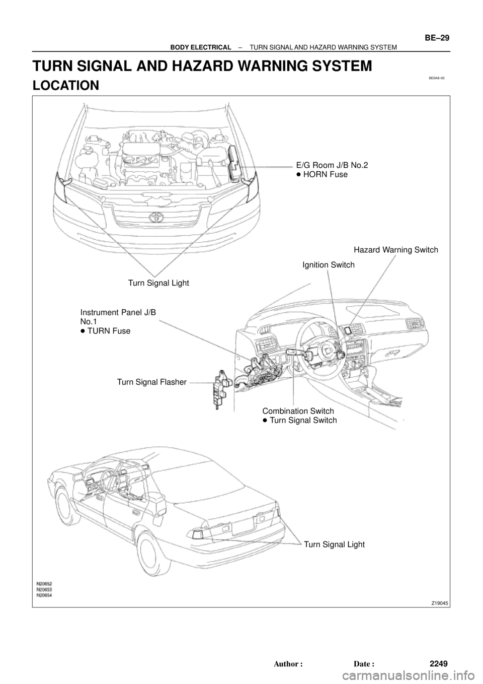
BE0A8±03
Z19045
E/G Room J/B No.2
� HORN Fuse
Turn Signal Light
Instrument Panel J/B
No.1
� TURN Fuse
Turn Signal Flasher
Combination Switch
� Turn Signal SwitchIgnition SwitchHazard Warning Switch
Turn Signal Light
± BODY ELECTRICALTURN SIGNAL AND HAZARD WARNING SYSTEM
BE±29
2249 Author�: Date�:
TURN SIGNAL AND HAZARD WARNING SYSTEM
LOCATION
Page 2124 of 4770

N20140
1 2 3
4
5 6 7 8 9 10
BE±30
± BODY ELECTRICALTURN SIGNAL AND HAZARD WARNING SYSTEM
2250 Author�: Date�:
INSPECTION
1")
BE0A9±02
N20150
Right
Left
2 31
BE1843
1 23
Turn Signal Light Bulbs (21 W)
N20140
1 2 3
4
5 6 7 8 9 10
BE±30
± BODY ELECTRICALTURN SIGNAL AND HAZARD WARNING SYSTEM
2250 Author�: Date�:
INSPECTION
1. INSPECT TURN SIGNAL SWITCH CONTINUITY
Switch positionTester connectionSpecified condition
Left turn1 ± 2Continuity
Neutral±No continuity
Right turn2 ± 3Continuity
If continuity is not as specified, replace the switch.
2. INSPECT TURN SIGNAL FLASHER OPERATION
(a) Connect the positive (+) lead from the battery to terminal
2 and the negative (±) lead to terminal 3.
(b) Connect the 2 turn signal light bulbs in parallel to each
other to terminals 1 and 3, check that the bulbs flash.
HINT:
The turn signal lights should flash 60 to 120 times per minute.
If one of the front or rear turn signal lights has an open circuit,
the number of flashes will be more than 140 per minute.
If operation is not as specified, replace the flasher.
3. INSPECT HAZARD WARNING SWITCH CONTINUITY
Switch positionTester connectionSpecified condition
Switch OFF7 ± 10Continuity
Switch ON5 ± 6 ± 9
7 ± 8Continuity
Illumination circuit2 ± 3Continuity
If continuity is not as specified, replace the switch.
Page 2140 of 4770

BE0AJ±03
Z18937
Connector ºAº Connector ºBº Connector ºCº
Connector ºAº
Connector ºBº
Connector ºCº
J±13±1±A J±16±1 J±13±1
1 2 3 4 5 6 7 8 9 10 11 12 1314 15 16 1 234 56 78 910111213 1 23456 78910111213
C7
C5
A2 B3
A1
C8
B15
C6
B6
A4
C4
B5
C10 B14
A13
B2
C1
B1
C9
A6
A11
A7
A10
A8
A9
C13
B8
B11
B12A5
C11
B4
B16 C2
A12
A3
B7
C3
C12
B9
B10
B13 F
E
T
S
ODOMETER
Fuel Level Warning
Seat Belt Warning
ABS Warning
Low Oil Pressure Warning
Cruise Control Indicator
Malfunction Indicator
O/D OFF Indicator
Light Failure Warning
Brake Warning
SLIP Indicator
TRAC Indicator
Washer Level Warning
Discharge Warning
Right Turn Indicator
Left Turn Indicator
Security Indicator
L
2
D
N
R
P
Illumination
Hi±Beam Indicator
Open Door Warning
SRS Warning
: Fuel Gauge
: Engine Coolant Temperature Gauge
: Tachometer
: Speedometer
No.
A
B
C1
2
3
4
5
6
7 8
9
10
11
12 13
14
15
16
2 3
4
5
6
7 8
9
10
11 12
131
2
3
4 5
6
7
8
9
10
11
12
13
F
E
T
SEngine coolant temperature sender gauge
Ground
Light failure sensor
Integration relay
Traction ECU
Park/neutral position switch (A/T)
O/D OFF switch (A/T)
IGN fuse
Turn signal switch
ST relay
Fuel sender gauge
Generator
Oil pressure switch
Fuel sender gauge
Parking brake switch and brake fluid level warning switch
Headlight dimmer switch
Headlight dimmer switch
Door courtesy switch
DOME fuse
ECU±B fuse
Airbag sensor assembly
ECM
No.1 Vehicle speed sensor Ground
Turn signal switch ECM
Traction ECU
ABS ECU
Ground No.1 Vehicle speed sensor
GAUGE fuse
Igniter
Security ECU
Cruise control ECU
Washer fluid level warning switch
Light control rheostat
TAIL fuse Park/neutral position switch (A/T) Park/neutral position switch (A/T) Park/neutral position switch (A/T) Park/neutral position switch (A/T)
Park/neutral position switch (A/T)Wire Harness Side
Bulb Check
Relay
N20107 N201081
BE±46
± BODY ELECTRICALCOMBINATION METER
2266 Author�: Date�:
CIRCUIT
Page 2161 of 4770
 Close(c) Open
A3 Type B:
± BODY ELECTRICALPOWER WINDOW CONTROL SYSTEM
BE±67
2287 Author�: Date�:
(f) Approximately 60 seconds later, connect the positive")
I21313
2
1
I12561
2
1
I12560
21
N20564
(b) Close(c) Open
A3 Type B:
± BODY ELECTRICALPOWER WINDOW CONTROL SYSTEM
BE±67
2287 Author�: Date�:
(f) Approximately 60 seconds later, connect the positive (+)
lead from the battery to terminal 1 and the negative (±)
lead to terminal 2, and check that the window begins to
descend.
If operation is not as specified, replace the motor.
13. Rear Door:
INSPECT POWER WINDOW MOTOR PTC THERM-
ISTOR OPERATION
(a) Disconnect the connector from the power window switch.
(b) Connect the positive (+) lead from the ammeter to termi-
nal 1 on the wire harness side connector and the negative
(±) lead to negative terminal of the battery.
(c) Connect the positive (+) lead from the battery to terminal
2 on the wire harness side connector, and raise the win-
dow to the fully position.
(d) Continue to apply voltage and check that the current
changes to less than 1 A within 4 to 90 seconds.
(e) Disconnect the leads from the terminals.
(f) Approximately 60 seconds later, connect the positive (+)
lead from the battery to terminal 2 and the negative (±)
lead to terminal 1, and check that the window begins to
descend.
If operation is not as specified, replace the motor.
14. Key±off power window signal:
INSPECT INTEGRATION RELAY (TYPE B) OPERA-
TION
HINT:
When the relay circuit is as specified, inspect the key±off power
window signal.
(a) Connect the positive (+) lead from the voltmeter to termi-
nal A3 and the negative (±) lead to body ground.
(b) Close the door with ignition switch turned to LOCK or
ACC, and check that the meter needle indicates battery
positive voltage.
(c) Open the door and check that the meter needle indicates
0 V.