Page 2585 of 4770
A03023A00417A03427
ON
IGF
(+)
w/o Immobiliser
w/ Immobiliser
IGF
(+)
± DIAGNOSTICSENGINE (5S±FE)
DI±165
400 Author�: Date�:
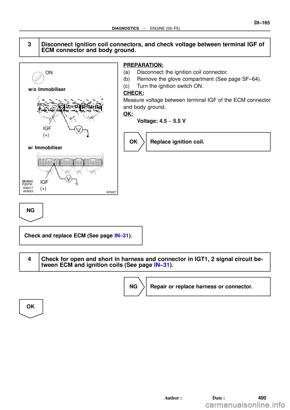
3 Disconnect ignition coil connectors, and check voltage between terminal IGF of
ECM connector and body ground.
PREPARATION:
(a) Disconnect the ignition coil connector.
(b) Remove the glove compartment (See page SF±64).
(c) Turn the ignition switch ON.
CHECK:
Measure voltage between terminal IGF of the ECM connector
and body ground.
OK:
Voltage: 4.5 ~ 5.5 V
OK Replace ignition coil.
NG
Check and replace ECM (See page IN±31).
4 Check for open and short in harness and connector in IGT1, 2 signal circuit be-
tween ECM and ignition coils (See page IN±31).
NG Repair or replace harness or connector.
OK
Page 2590 of 4770
 Stop
Light
(RH) G±R
2
52
5
W±B
W±B
BP High
Mount
Stop
Light
2
1R
A
A")
A03604
ECM
STP 4
E7
G±W G±WJ27 J28 1R 1R
1SJ27
J/C
AC Instrument Panel J/B
5
2 4
7
12
G±WLight
Failure
Sensor
Stop
Light
(LH) Stop
Light
(RH) G±R
2
52
5
W±B
W±B
BP High
Mount
Stop
Light
2
1R
A
A
J40
J/C
BL
1
W±B
Stop Light
Switch
2
BatteryW±B W
1C 7
STOP
41BInstrument
Panel J/B
B±R
B±R
F9 2 F9 1
ALT
F4MAIN
FL
FL Block
G±W
1
*1: w/o Immobiliser
*2: w/ Immobiliser(*1) (*2)
E79 DI±170
± DIAGNOSTICSENGINE (5S±FE)
405 Author�: Date�:
DTC P1520 Stop Light Switch Signal Malfunction (Only
for A/T)
CIRCUIT DESCRIPTION
This signal is used to detect when the brakes have been applied. The STP signal voltage is the same as
the voltage supplied to the stop lights.
The STP signal is used mainly to control the fuel cut±off engine speed. (The fuel cut±off engine speed is
reduced slightly when the vehicle is braking.)
DTC No.DTC Detecting ConditionTrouble Area
P1520Stop light switch does not turn off even once vehicle is driven
(2 trip detection logic)�Short in stop light switch signal circuit
�Stop light switch
�ECM
WIRING DIAGRAM
DI01H±07
Page 2592 of 4770
A03025A03429
Brake Pedal
Depressed
ON ON
STP (+) Brake Pedal
Released
w/o Immobiliser
w/ Immobiliser
STP (+)
DI±172
± DIAGNOSTICSENGINE (5S±FE)
407 Author�: Date�:
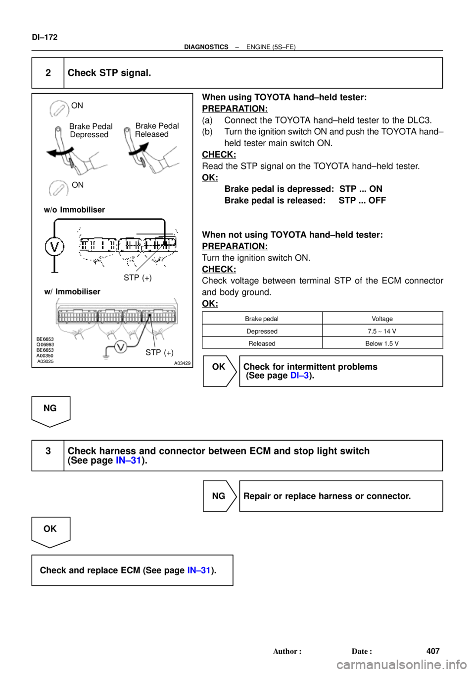
2 Check STP signal.
When using TOYOTA hand±held tester:
PREPARATION:
(a) Connect the TOYOTA hand±held tester to the DLC3.
(b) Turn the ignition switch ON and push the TOYOTA hand±
held tester main switch ON.
CHECK:
Read the STP signal on the TOYOTA hand±held tester.
OK:
Brake pedal is depressed: STP ... ON
Brake pedal is released: STP ... OFF
When not using TOYOTA hand±held tester:
PREPARATION:
Turn the ignition switch ON.
CHECK:
Check voltage between terminal STP of the ECM connector
and body ground.
OK:
Brake pedalVoltage
Depressed7.5 ~ 14 V
ReleasedBelow 1.5 V
OK Check for intermittent problems
(See page DI±3).
NG
3 Check harness and connector between ECM and stop light switch
(See page IN±31).
NG Repair or replace harness or connector.
OK
Check and replace ECM (See page IN±31).
Page 2597 of 4770
± DIAGNOSTICSENGINE (5S±FE)
DI±177
412 Author�: Date�:
INSPECTION PROCEDURE
HINT:
This diagnostic chart is based on the premise that the engine is cranked normally. If the engine is not
cranked, proceed to the problem symptoms table on page DI±28.
TOYOTA hand±held tester:
1 Connect TOYOTA hand±held tester, and check STA signal.
PREPARATION:
(a) Connect the TOYOTA hand±held tester to the DLC3.
(b) Turn the ignition switch ON and push the TOYOTA hand±held tester main switch ON.
CHECK:
Read STA signal on the TOYOTA hand±held tester while the starter operates.
OK:
Ignition Switch PositionONSTART
STA signalOFFON
OK Proceed to next circuit inspection shown on
problem symptoms table (See page DI±28).
NG
2 Check for open in harness and connector between ECM and starter relay
(Marking: ST) (See page IN±31).
NG Repair or replace harness or connector.
OK
Check and replace ECM (See page IN±31).
Page 2603 of 4770
A00325
BatteryMAIN IG Switch
AM2EFI
MAIN
FLStarter ST RelayPark/Neutral Position Switch
(Clutch Start Switch)EFI RelayCIR OPN Relay
Fuel Pump
ECM
FC
Tr
STA
NE (STA Signal)
(NE Signal) IGN
STARTER ST
± DIAGNOSTICSENGINE (5S±FE)
DI±183
418 Author�: Date�:
Fuel Pump Control Circuit
CIRCUIT DESCRIPTION
In the diagram below, when the engine is cranked, current flows from terminal ST of the ignition switch to
the starter relay coil and also current flows to terminal STA of ECM (STA signal).
When the STA signal and NE signal are input to the ECM, Tr is turned ON, current flows to coil of the circuit
opening relay, the relay switches on, power is supplied to the fuel pump and the fuel pump operates.
While the NE signal is generated (engine running), the ECM keeps Tr ON (circuit opening relay ON) and the
fuel pump also keeps operating.
DI01M±05
Page 2619 of 4770

DI±199
434 Author�: Date�:
(b) Check the DLC3.
The vehicles ECM uses ISO 9141±2 for communication.
The terminal arrangement of DLC3 complies with S")
N09214
DLC3
S04159
± DIAGNOSTICSENGINE (1MZ±FE)
DI±199
434 Author�: Date�:
(b) Check the DLC3.
The vehicle's ECM uses ISO 9141±2 for communication.
The terminal arrangement of DLC3 complies with SAE
J1962 and matches the ISO 9141±2 format.
Terminal No.Connection / Voltage or ResistanceCondition
7Bus � Line / Pulse generationDuring transmission
4Chassis Ground e Body Ground /1 W or lessAlways
5Signal Ground e Body Ground /1 W or lessAlways
16Battery Positive e Body Ground /9 ~ 14 VAlways
HINT:
If your display shows ºUNABLE TO CONNECT TO VEHICLEº
when you have connected the cable of the OBD II scan tool or
TOYOTA hand±held tester to DLC3, turned the ignition switch
ON and operated the scan tool, there is a problem on the ve-
hicle side or tool side.
�If communication is normal when the tool is connected to
another vehicle, inspect DLC3 on the original vehicle.
�If communication is still not possible when the tool is con-
nected to another vehicle, the problem is probably in the
tool itself, so consult the Service Department listed in the
tool's instruction manual.
2. INSPECT DIAGNOSIS (Normal Mode)
(a) Check the MIL.
(1) The MIL comes on when the ignition switch is turned
ON and the engine is not running.
HINT:
If the MIL does not light up, troubleshoot the combination meter
(See page BE±46).
(2) When the engine started, the MIL should go off. If
the lamp remains on, the diagnosis system has de-
tected a malfunction or abnormality in the system.
(b) Check the DTC.
NOTICE:
TOYOTA hand±held tester only: When the diagnosis sys-
tem is switched from normal mode to check mode, it erases
all DTC and freezed frame data recorded in normal mode.
So before switching modes, always check the DTC and
freezed frame data, and note them down.
(1) Prepare the OBD II scan tool (complying with SAE
J1978) or TOYOTA hand±held tester.
Page 2622 of 4770

437 Author�: Date�:
4. FAIL±SAFE CHART
If any of the following codes is recorded, the ECM enters fail±safe mode.
DTC No.Fail±Safe OperationFail±Safe Deactiva")
DI±202
± DIAGNOSTICSENGINE (1MZ±FE)
437 Author�: Date�:
4. FAIL±SAFE CHART
If any of the following codes is recorded, the ECM enters fail±safe mode.
DTC No.Fail±Safe OperationFail±Safe Deactivation Conditions
P0100Ignition timing fixed at 10° BTDCReturned to normal condition
P0110Intake air temperature is fixed at 20°C (68°F)Returned to normal condition
P0115Engine coolant temperature is fixed at 80°C (176°F)Returned to normal condition
P0120VTA is fixed at 0°
The following condition must be repeated at least 2 times
consecutively
(a) Vehicle speed: 0km/h (0mph)
(b) VTA ��0.1 V and � 0.95 V
P0135
P0141
P0155The heater circuit in which an abnormality is detected is
turned offIgnition switch OFF
P0325
P0330Max. timing retardationIgnition switch OFF
P1300Fuel cutIGF signal is detected for 6 consecutive ignition
5. CHECK FOR INTERMITTENT PROBLEMS
TOYOTA HAND±HELD TESTER only:
By putting the vehicle's ECM in check mode, 1 trip detection logic is possible instead of 2 trip detection logic
and sensitivity to detect open circuits is increased. This makes it easier to detect intermittent problems.
(1) Clear the DTC (See page DI±197).
(2) Set the check mode (See page DI±197).
(3) Perform a simulation test (See page IN±21).
(4) Check the connector and terminal (See page IN±31).
(5) Handle the connector (See page IN±31).
6. BASIC INSPECTION
When the malfunction code is not confirmed in the DTC check, troubleshooting should be performed in the
order for all possible circuits to be considered as the causes of the problems. In many cases, by carrying
out the basic engine check shown in the following flow chart, the location causing the problem can be found
quickly and efficiently. Therefore, use of this check is essential in engine troubleshooting.
1 Is battery positive voltage 11 V or more when engine is stopped ?
NO Charge or replace battery.
YES
Page 2629 of 4770

DI±209
444 Author�: Date�:
(b) TOYOTA Enhanced Signals.
TOYOTA hand±held tester displayMeasurement ItemNormal Condition*
MISFIRE RPMEngine RPM for first misfire rangeM")
± DIAGNOSTICSENGINE (1MZ±FE)
DI±209
444 Author�: Date�:
(b) TOYOTA Enhanced Signals.
TOYOTA hand±held tester displayMeasurement ItemNormal Condition*
MISFIRE RPMEngine RPM for first misfire rangeMisfire 0: 0 rpm
MISFIRE LOADEngine load for first misfire rangeMisfire 0: 0 g/r
INJECTORFuel injection time for cylinder No.1Idling: 1.6 ~ 2.9 ms
IAC DUTY RATIOIntake Air Control Valve Duty Ratio
Opening ratio rotary solenoid type IAC valveIdling: 27 ~ 47 %
STARTER SIGStarter SignalCranking: ON
CTP SIGClosed Throttle Position SignalThrottle Fully Closed: ON
A/C SIGA/C Switch SignalA/C ON: ON
PNP SWPark/Neutral Position Switch SignalP or N position: ON
ELCTRCL LOAD SIGElectrical Load SignalDefogger switch ON: ON
STOP LIGHT SWStop Light Switch SignalStop light switch ON: ON
PS OIL PRESS SWPower Steering Oil Pressure Switch SignalTurn steering wheel: ON
FC IDLFuel Cut Idle: Fuel cut when throttle valve fully
closed, during decelerationFuel cut operating: ON
FC TAUFuel Cut TAU: Fuel cut during very light loadFuel cut operating: ON
CYL#1 ~ CYL#6Abnormal revolution variation for each cylinder0%
IGNITIONTotal number of ignition for every 1,000 revolu-
tions0 ~ 3,000
EGRT GASEGR Gas Temperature Sensor Value
EGR not operating:
Temperature between intake air temp. and
engine coolant temp.
INTAKE CTRL VSVIntake Air Control Valve VSV SignalVSV operating: ON
EGR SYSTEMEGR system operating conditionIdling: OFF
A/C CUT SIGA/C Cut SignalA/C S/W OFF: ON
FUEL PUMPFuel Pump SignalIdling: ON
EVAP (PURGE) VSVEVAP VSV SignalVSV operating: Above 30%
VAPOR PRESS VSVVapor Pressure VSV SignalVSV operating: ON (TANK)
*: If no conditions are specifically stated for ºldlingº, it means the shift lever is at N or P position, the A/C switch
is OFF and all accessory switches are OFF.

EFI RelayCIR OPN Relay
Fuel Pump
ECM
FC
Tr
STA
NE (STA Signal)
(NE Signal) IGN
STARTER ST
�")