Page 2805 of 4770
± DIAGNOSTICSENGINE (1MZ±FE)
DI±385
620 Author�: Date�:
INSPECTION PROCEDURE
HINT:
This diagnostic chart is based on the premise that the engine is cranked normally. If the engine is not
cranked, proceed to the problem symptoms table on page DI±221.
TOYOTA hand±held tester
1 Connect TOYOTA hand±held tester, and check STA signal.
PREPARATION:
(a) Connect the TOYOTA hand±held tester to the DLC3.
(b) Turn the ignition switch ON and push the TOYOTA hand±held tester main switch ON.
CHECK:
Read STA signal on the TOYOTA hand±held tester while starter operates.
OK:
Ignition switch positionONSTART
STA signalOFFON
OK Proceed to next circuit inspection shown on
problem symptom table (See page DI±221).
NG
2 Check for open in harness and connector between ECM and starter relay
(See page IN±31).
NG Repair or replace or connector.
OK
Check and replace ECM (See page IN±31).
Page 2810 of 4770

625 Author�: Date�: �
The diagnosis system operates in normal mode
during normal vehicle use, and also has a check
mode for technicians to")
N09214
DLC3 DI±390
± DIAGNOSTICSAUTOMATIC TRANSAXLE (A140E)
625 Author�: Date�: �
The diagnosis system operates in normal mode
during normal vehicle use, and also has a check
mode for technicians to simulate malfunction symp-
toms and perform troubleshooting. Most DTCs use
2 trip detection logic(*) to prevent erroneous detec-
tion. By switching the ECM to check mode when
troubleshooting, the technician can cause the MIL
to light up and for a malfunction that is only detected
once or momentarily.
(TOYOTA hand±held tester) (See page DI±401)
�*2 trip detection logic:
When a logic malfunction is first detected, the mal-
function is temporarily stored in the ECM memory.
If the same malfunction is detected again during the
2nd test drive, this 2nd detection causes the MIL to
light up.
(b) Inspect the DLC3.
The vehicle's ECM uses V.P.W. (Variable Pulse Width) for
communication to comply with SAE J1850. The terminal
arrangement of DLC3 complies with SAE J1962 and
matches the V.P.W. format.
Tester connectionConditionSpecified condition
2 (Bus � Line) ± 5 (Signal ground)During communicationPulse generation
4 (Chassis Ground) ± BodyAlways1 W or less
5 (Signal Ground) ± BodyAlways1 W or less
16 (B+) ± BodyAlways9 ± 14 V
HINT:
If your display shows ºUNABLE TO CONNECT TO VEHICLEº
when you have connected the cable of OBD II scan tool or TOY-
OTA hand±held tester to DLC3, turned the ignition switch ON
and operated the scan tool, there is a problem on the vehicle
side or tool side.
�If communication is normal when the tool is connected to
another vehicle, inspect DLC3 on the original vehicle.
�If communication is still not possible when the tool is con-
nected to another vehicle, the problem is probably in the
tool itself, so consult the Service Department listed in the
tool's instruction manual.
Page 2839 of 4770
D01808
1
E3P
*1
Transaxle
Shift Solenoid
Valve SLECM
B+
: w/ Engine Immobiliser System
: w/o Engine Immobiliser SystemSL
E91 20
*1
*2
E9
*2
± DIAGNOSTICSAUTOMATIC TRANSAXLE (A140E)
DI±419
654 Author�: Date�:
DTC P0773 Shift Solenoid E Electrical Malfunction
(Shift Solenoid Valve SL)
CIRCUIT DESCRIPTION
The shift solenoid valve SL is turned ON and OFF by signals from the ECM to control the hydraulic pressure
acting on the lock±up relay valve, which then controls operation of the lock±up clutch.
Fail safe function
If the ECM detects a malfunction, it turns the shift solenoid valve SL OFF.
DTC No.DTC Detecting ConditionTrouble Area
P0773
Either (a) or (b) is detected for 1 time.(2 trip detection logic)
(a) Solenoid resistance is 8 W or less short circuit when sole-
noid is energized.
(b) Solenoid resistance is 100 kW or more open circuit when
solenoid is not energized.
�Open or short in shift solenoid valve SL circuit
�Shift solenoid valve SL
�ECM
WIRING DIAGRAM
DI035±02
Page 2846 of 4770
(+) (+)
(±)
Position
P, N
R
D
2
LNSW±Body
groundR±Body
ground2±Body
groundL±Body
grou")
D00043 Q08479BE3840D00994
w/ Engine Immobiliser System
w/o Engine Immobiliser SystemON
NSW
LL
2
R
NSWR
2
(±)(+) (+)
(±)
Position
P, N
R
D
2
LNSW±Body
groundR±Body
ground2±Body
groundL±Body
ground
0 V
0 V0 V0 V
0 V
0 V
0 V 0 V
0 V
0 V 0 V
0 V
0 V 9 ~ 14 V*
9 ~ 14 V
9 ~ 14 V
9 ~ 14 V9 ~ 14 V
9 ~ 14 V 9 ~ 14 V*
DI±426
± DIAGNOSTICSAUTOMATIC TRANSAXLE (A140E)
661 Author�: Date�:
INSPECTION PROCEDURE
1 Read PNP, REVERSE, 2ND and LOW signals.
When using TOYOTA hand±held tester:
PREPARATION:
(a) Remove the DLC3 cover.
(b) Connect a TOYOTA hand±held tester to the DLC3.
(c) Turn the ignition switch ON and TOYOTA hand±held tes-
ter main switch ON.
CHECK:
Shift the shift lever into the P, R, N, 2 and L positions, and read
the PNP, REVERSE, 2ND and LOW signals on the TOYOTA
hand±held tester.
OK:
Shift positionSignal
22ND OFF " ON
LLOW OFF " ON
RREVERSE OFF " ON
P, NPNP OFF " ON
When not using TOYOTA hand±held tester:
PREPARATION:
Turn the ignition switch ON.
CHECK:
Measure voltage between terminals NSW, 2, L and R of ECM
and body ground when the shift lever is shifted in the following
positions.
OK:
HINT:
The voltage will drop slightly due to lighting up of the back up
light.
OK Proceed to next circuit inspection shown on
matrix chart (See page DI±405).
NG
Page 2853 of 4770
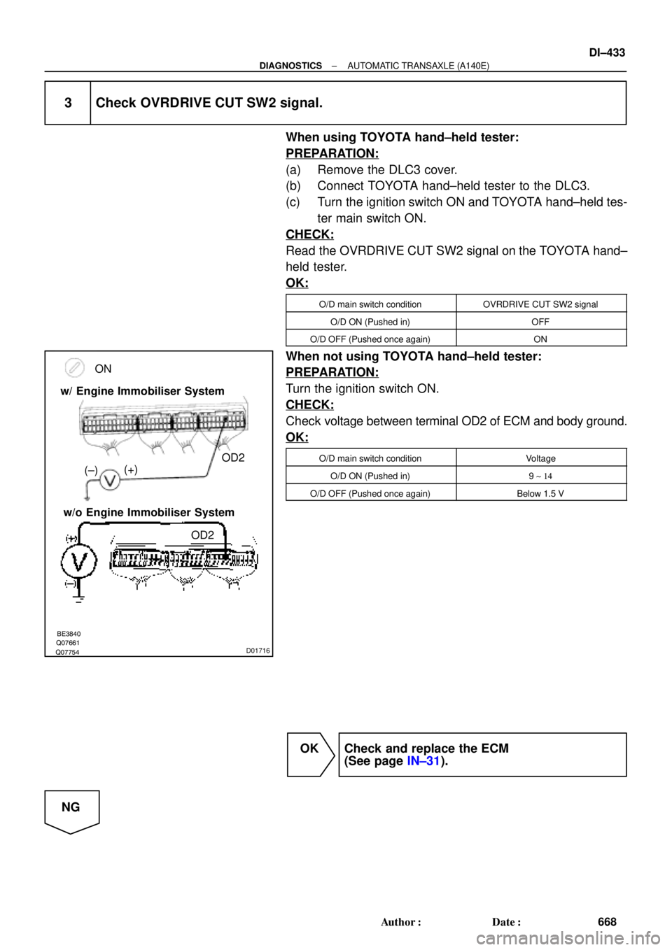
Q07754Q07661BE3840D01716
ON
(+)
OD2
(±) w/ Engine Immobiliser System
w/o Engine Immobiliser System
OD2
± DIAGNOSTICSAUTOMATIC TRANSAXLE (A140E)
DI±433
668 Author�: Date�:
3 Check OVRDRIVE CUT SW2 signal.
When using TOYOTA hand±held tester:
PREPARATION:
(a) Remove the DLC3 cover.
(b) Connect TOYOTA hand±held tester to the DLC3.
(c) Turn the ignition switch ON and TOYOTA hand±held tes-
ter main switch ON.
CHECK:
Read the OVRDRIVE CUT SW2 signal on the TOYOTA hand±
held tester.
OK:
O/D main switch conditionOVRDRIVE CUT SW2 signal
O/D ON (Pushed in)OFF
O/D OFF (Pushed once again)ON
When not using TOYOTA hand±held tester:
PREPARATION:
Turn the ignition switch ON.
CHECK:
Check voltage between terminal OD2 of ECM and body ground.
OK:
O/D main switch conditionVoltage
O/D ON (Pushed in)9 ~ 14
O/D OFF (Pushed once again)Below 1.5 V
OK Check and replace the ECM
(See page IN±31).
NG
Page 2859 of 4770

DI±439
674 Author�: Date�: �
The diagnosis system operates in normal mode
during normal vehicle use, and also has a check
mode for technicians to simu")
N09214
± DIAGNOSTICSAUTOMATIC TRANSAXLE (A541E)
DI±439
674 Author�: Date�: �
The diagnosis system operates in normal mode
during normal vehicle use, and also has a check
mode for technicians to simulate malfunction symp-
toms and perform troubleshooting. Most DTCs use
2 trip detection logic(*) to prevent erroneous detec-
tion. By switching the ECM to check mode when
troubleshooting, the technician can cause the MIL
to light up and for a malfunction that is only detected
once or momentarily.
(TOYOTA hand±held tester) (See page DI±438)
�*2 trip detection logic:
When a logic malfunction is first detected, the mal-
function is temporarily stored in the ECM memory.
If the same malfunction is detected again during the
2nd test drive, this 2nd detection causes the MIL to
light up.
(b) Inspect the DLC3.
The vehicle's ECM uses ISO 9141±2 for communication.
The terminal arrangement of DLC3 complies with SAE
J1962 and matches the ISO 9141±2 format.
Tester connectionConditionSpecified condition
7 (Bus � Line) ± 5 (Signal ground)During communicationPulse generation
4 (Chassis Ground) ± BodyAlways1 W or less
5 (Signal Ground) ± BodyAlways1 W or less
16 (B+) ± BodyAlways9 ± 14 V
HINT:
If your display shows ºUNABLE TO CONNECT TO VEHICLEº
when you have connected the cable of OBD II scan tool or TOY-
OTA hand±held tester to DLC3, turned the ignition switch ON
and operated the scan tool, there is a problem on the vehicle
side or tool side.
(1) If communication is normal when the tool is con-
nected to another vehicle, inspect DLC3 on the orig-
inal vehicle.
(2) If communication is still not possible when the tool
is connected connected to another vehicle, the
problem is probably in the tool itself, so consult the
Service Department listed in the tool's instruction
manual.
Page 2888 of 4770

D01093
Transaxle
Shift Solenoid
Valve SL
2
E3P±L
E10B+
SLECM
*1: Except California, w/ Engine Immobilizer and / or TRAC
*2: California, w/ Engine Immobilizer and / or TRACE11 *2*1
27
9
Y DI±468
± DIAGNOSTICSAUTOMATIC TRANSAXLE (A541E)
703 Author�: Date�:
DTC P0773 Shift Solenoid E Electrical Malfunction
(Shift Solenoid Valve SL)
CIRCUIT DESCRIPTION
The shift solenoid valve SL is turned ON and OFF by signals from the ECM to control the hydraulic pressure
acting on the lock±up relay valve, which then controls operation of the lock±up clutch.
Fail safe function
If the ECM detects a malfunction, it turns the shift solenoid valve SL OFF.
DTC No.DTC Detecting ConditionTrouble Area
P0773
Either (a) or (b) are detected for 1 time.
(2 trip detection logic)
(a) Solenoid resistance is 8 W or less short circuit when sole-
noid is energized.
(b) Solenoid resistance is 100 kW or more open circuit when
solenoid is not energized.
�Open or short in shift solenoid valve SL circuit
�Shift solenoid valve SL
�ECM
WIRING DIAGRAM
DI02N±02
Page 2902 of 4770

BE3840D00052D00836D01914
Except California, w/ Engine Immobilizer
and / or TRAC:
California, w/ Engine Immobilizer
and / or TRAC:ON
L
NSW
2
R
2R
L
NSW
Position
P, N
R
D
2
LNSW±Body
groundR±Body
ground2±Body
groundL±Body
ground
0 V
0 V0 V0 V
0 V
0 V
0 V 0 V
0 V
0 V 0 V
0 V
0 V 9 ~ 14 V*
9 ~ 14 V
9 ~ 14 V
9 ~ 14 V9 ~ 14 V
9 ~ 14 V 9 ~ 14 V* DI±482
± DIAGNOSTICSAUTOMATIC TRANSAXLE (A541E)
717 Author�: Date�:
INSPECTION PROCEDURE
1 Read PNP, REVERSE, 2ND and LOW signals.
When using TOYOTA hand±held tester.
PREPARATION:
(a) Remove the DLC3 cover.
(b) Connect a TOYOTA hand±held tester to the DLC3.
(c) Turn the ignition switch ON and TOYOTA hand±held tes-
ter main switch ON.
CHECK:
Shift lever into the P, R, N, 2 and L positions, and read the PNP,
REVERSE, 2ND and LOW signals on the TOYOTA hand±held
tester.
OK:
Shift positionSignal
22ND OFF " ON
LLOW OFF " ON
RREVERSE OFF " ON
P, NNSW OFF " ON
When not using TOYOTA hand±held tester.
PREPARATION:
Turn the ignition switch ON.
CHECK:
Measure voltage between terminals NSW, 2, L and R of ECM
and body ground when the shift lever is shifted to the following
positions.
OK:
HINT:
*: The voltage will drop slightly due to lighting up of the back up
light.


DI±419
654 Author")