Page 4239 of 4770
RS0F0±01
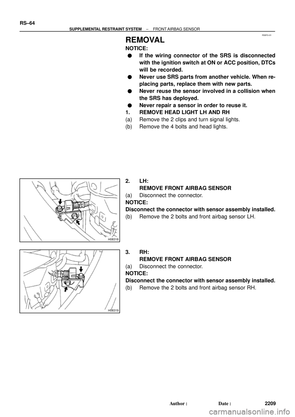
H08318
H08319
RS±64
± SUPPLEMENTAL RESTRAINT SYSTEMFRONT AIRBAG SENSOR
2209 Author�: Date�:
REMOVAL
NOTICE:
�If the wiring connector of the SRS is disconnected
with the ignition switch at ON or ACC position, DTCs
will be recorded.
�Never use SRS parts from another vehicle. When re-
placing parts, replace them with new parts.
�Never reuse the sensor involved in a collision when
the SRS has deployed.
�Never repair a sensor in order to reuse it.
1. REMOVE HEAD LIGHT LH AND RH
(a) Remove the 2 clips and turn signal lights.
(b) Remove the 4 bolts and head lights.
2. LH:
REMOVE FRONT AIRBAG SENSOR
(a) Disconnect the connector.
NOTICE:
Disconnect the connector with sensor assembly installed.
(b) Remove the 2 bolts and front airbag sensor LH.
3. RH:
REMOVE FRONT AIRBAG SENSOR
(a) Disconnect the connector.
NOTICE:
Disconnect the connector with sensor assembly installed.
(b) Remove the 2 bolts and front airbag sensor RH.
Page 4242 of 4770
 Install the front airbag sensor with")
RS01P±14
H06728
LH:
RH:
± SUPPLEMENTAL RESTRAINT SYSTEMFRONT AIRBAG SENSOR
RS±67
2212 Author�: Date�:
INSTALLATION
1. INSTALL FRONT AIRBAG SENSOR LH AND RH
(a) Install the front airbag sensor with the arrow on the sensor
facing toward the front of the vehicle.
Torque: 20 N´m (205 kgf´cm, 15 ft´lbf)
NOTICE:
�Connection of the connector is done after the sensor
assembly has been installed.
�Make sure the sensor is installed with the specified
torque.
�If the sensor has been dropped, or there are cracks,
dents or other defects in the case, brackets or con-
nector, replace the removed sensor with a new one.
�The front sensor is equipped with an electrical con-
nection check mechanism. Be sure to lock this mech-
anism securely when connecting the connector. If the
connector is not securely locked, a malfunction code
will be detected by the diagnostic system.
(b) Connect the front airbag sensor connector.
2. INSTALL HEAD LIGHT LH AND RH
(See page BE±28)
3. INSTALL TURN SIGNAL LIGHT LH AND RH
Page 4300 of 4770
F01476
Key Unlock Warning Switch
Column Upper Bracket Ignition Switch
Energy Absorbing PlateTransponder Key Coil Key Cylinder Lamp Assembly
Key
Interlock
Solenoid Key Cylinder
Transponder Key
Amplifier
Energy Absorbing Plate
Guide� Energy Absorbing Clip
Energy Absorbing Plate
Energy Absorbing Plate
Guide
� Energy Absorbing Clip Column TubeTilt Lever
Return Spring
� Tapered±Head Bolt Column Upper Tube Turn Signal Bracket
Lower Column Tube AttachmentColumn Tube Support
7 (70, 61 in.´lbf)
19 (195, 14)
N´m (kgf´cm, ft´lbf): Specified torque
� Non±reusable partw/ ENGINE IMMOBILISER SYSTEM:
A/T: SR±10
± STEERINGTILT STEERING COLUMN
2105 Author�: Date�:
Page 4303 of 4770

SR06J±01
W03333
Screw Extractor
W03334
± STEERINGTILT STEERING COLUMN
SR±13
2108 Author�: Date�:
DISASSEMBLY
NOTICE:
When using a vise, do not overtighten it.
1. w/ ENGINE IMMOBILISER SYSTEM:
REMOVE TRANSPONDER KEY COIL WITH KEY CYL-
INDER LAMP ASSEMBLY
Remove the screw.
2. w/ ENGINE IMMOBILISER SYSTEM:
REMOVE KEY CYLINDER LAMP ASSEMBLY
Remove the lamp assembly from the key coil.
3. w/o ENGINE IMMOBILISER SYSTEM:
REMOVE KEY CYLINDER LAMP ASSEMBLY
Remove the screw.
4. REMOVE COLUMN UPPER BRACKET AND COLUMN
UPPER CLAMP
(a) Using a centering punch, mark the center of the 2 ta-
pered±head bolts.
(b) Using a 3±4 mm (0.12±0.16 in.) drill, drill into the 2 bolts.
(c) Using a screw extractor, remove the 2 bolts.
5. REMOVE TURN SIGNAL BRACKET
Remove the 2 bolts.
6. REMOVE TILT LEVER RETURN SPRING
7. REMOVE COLUMN TUBE SUPPORT
(a) Remove the bolt and washer.
(b) Remove the tube support with lower column tube attach-
ment.
(c) Remove the tube attachment from the tube support.
8. REMOVE 2 ENERGY ABSORBING PLATES
(a) Using pliers, remove the energy absorbing clip.
(b) Remove the energy absorbing plate, energy absorbing
plate guide.
Page 4305 of 4770
 Install the en")
SR06L±01
W03347
W03337
± STEERINGTILT STEERING COLUMN
SR±15
2110 Author�: Date�:
REASSEMBLY
NOTICE:
When using a vise, do not overtighten it.
1. INSTALL 2 ENERGY ABSORBING PLATES
(a) Install the energy absorbing plate guide and absorbing
plate.
(b) Install the new energy absorbing clip.
2. INSTALL COLUMN TUBE SUPPORT
(a) Install the tube attachment to the tube support.
(b) Torque the bolt and washer.
Torque: 19 N´m (195 kgf´cm, 14 ft´lbf)
3. INSTALL TILT LEVER RETURN SPRING
4. INSTALL TURN SIGNAL BRACKET
Torque the 2 bolts.
Torque: 7 N´m (70 kgf´cm, 61 in.´lbf)
5. INSTALL COLUMN UPPER BRACKET AND COLUMN
UPPER CLAMP
Tighten the 2 new tapered±head bolts until the bolt heads break
off.
6. w/ ENGINE EMMOBILISER SYSTEM:
INSTALL KEY CYLINDER LAMP ASSEMBLY
Install the lamp assembly to the key coil.
7. w/ ENGINE EMMOBILISER SYSTEM:
INSTALL TRANSPONDER KEY COIL WITH KEY CYL-
INDER LAMP ASSEMBLY
Tighten the screw.
8. w/o ENGINE EMMOBILISER SYSTEM:
INSTALL KEY CYLINDER LAMP ASSEMBLY
Tighten the screw.
Page 4418 of 4770
 are operated.
Poo")
Vehicles with power antennas may exhibit audible electrical noise on weak AM stations when
various electrical accessories (turn signals, rear defogger, cruise control, brakes, etc.) are operated.
Poor antenna grounding can cause this condition.
To eliminate or reduce the intensity of the noise, use the following repair procedure:
AM STATIC NOISE ON VEHICLES WITH POWER ANTENNASPage 1 of 2
OCTOBER 25, 1996
AUDIO
AU002±96
ALL MODELS
REPAIR PROCEDURE:
1. Tune the radio to a strong, static±free AM
station and slowly move the tip of the
antenna mast forward and back
approximately 2 inches (Fig. 1). If static
noise is not heard, go to Step 2. If static
noise is heard during antenna movement,
replace the antenna mast and go to Step 3.
NOTE:Do not touch the antenna mast with
your bare hands. Use a glove or
nonmetallic object to move the
antenna. (If you touch the antenna
with your hands, you will change the
antenna sensitivity).
2. Remove the antenna mast and inspect the
base of the mast for corrosion and damage
(Fig. 2). Clean with 1500 grit sandpaper.
3. Remove the antenna assembly and inspect
the inner fender around the antenna hole
for corrosion (Fig. 3). Clean with 1500 grit
sandpaper.
Fig. 1
Fig. 2
Fig. 3
Inspection
Area
Page 4567 of 4770

EVAP SYSTEM OPERATION INFORMATION ± EG005-01 April 27, 2001
Page 8 of 14
Purge VSV Operation ± P0441
At a predetermined point, the ECM closes
the CCV and opens the bypass VSV
causing vacuum to increase in the entire
EVAP system.
The ECM continues to operate the purge
VSV until the vacuum is increased to a
specified point at which time the ECM
closes the purge VSV (see Figure 2).
If the vacuum did not increase, or if the
vacuum increased beyond the specified
limit, the ECM judges the purge VSV and
related components to be faulty.
Hole Detection P0440 and P0442
The rate of pressure increase as detected
by the vapor pressure signal indicates the
if there is a leak and if it is a large or
small leak.
After purge VSV operation, the purge
VSV is turned off sealing the vacuum in
the system and the ECM begins to
monitor the pressure increase (see Figure
3). Some increase is normal. A very rapid,
sharp increase in pressure indicates a
leak in the EVAP system and sets the
DTC P0440.
This monitoring method is also able to
distinguish what is called the small leak
detection. A pressure rise just above
normal indicates a very small hole and
will set the DTC P0442.Except ECHO
Figure 2. Vacuum Application
Late Type
System
Monitor
Sequence
(Continued)
ECHO
Figure 2. Vacuum Application
Except ECHO
Figure 3. System Sealed
ECHO
Figure 3. System Sealed
Page 4587 of 4770

Toyota Supports ASE CertificationPage 1 of 1
EL006±99Title:
ENGINE IMMOBILIZER SYSTEM
PRECAUTIONS
Models:
All Models
Technical Service
BULLETIN
October 8, 1999
REVISION NOTICE:
The information contained in this TSB updates EL001±98 dated January 23, 1998.
This bulletin applies to 1998 and newer Toyota vehicles. When using an immobilizer key
containing a transponder chip, observe the following precautions while starting the engine.
1. The key ring should not
rest on or be
pressed against the key grip.
2. Do not
place any other transponder
devices on the same key ring. Such
devices would include transponder
equipped units used for charging fuel.
3. Do not
place any other immobilizer
keys on the same key ring with the
key used to start the vehicle.
4. If the above precautions are not
observed and an engine starting or
running problem occurs, remove all
items which may interfere with the
ignition key transponder signal. Turn
off the engine and then restart.
�All Toyota models equipped with an engine immobilizer system.
OP CODEDESCRIPTIONTIMEOPNT1T2
N/ANot Applicable to Warranty±±±±
ELECTRICAL
Introduction
Applicable
Vehicles
Warranty
Information