Page 227 of 4770
ON±VEHICLE INSPECTION
1. CHECK FUEL PUMP OPERATION
(a) Using SST; connect terminals +B and FP of the data
link connector 1.
SST 09843±18020
(b) Turn the ignition switch ON.
NOTICE: Do not start the engine.
FUEL PUMP
SYSTEM CIRCUIT
± 5S±FE ENGINEMFI/SFI SYSTEMEG1±177
Page 228 of 4770
2. CHECK FUEL PRESSURE
(a) Check that the battery voltages is above 12 volts.
(b) Disconnect the negative (±) terminal cable from the
battery.
CAUTION: Work must be started after 90 seconds from
the time the ignition switch is turned to the ªLOCKº
position and the negative (±) terminal cable is discon±
nected from the battery.
If there is no pressure, check the following parts:
wFusible link
wFuses (AM2 30A, EFI 15A, IGN 7.5A)
wEFI main relay
wFuel pump
wWiring connections (c) Check that there is pressure in the hose from the fuel
filter.
HINT: At this time, you will hear fuel return noise.
(e) Remove the SST.
SST 09843±18020 (d) Turn the ignition switch OFF.
± 5S±FE ENGINEMFI/SFI SYSTEMEG1±178
Page 229 of 4770
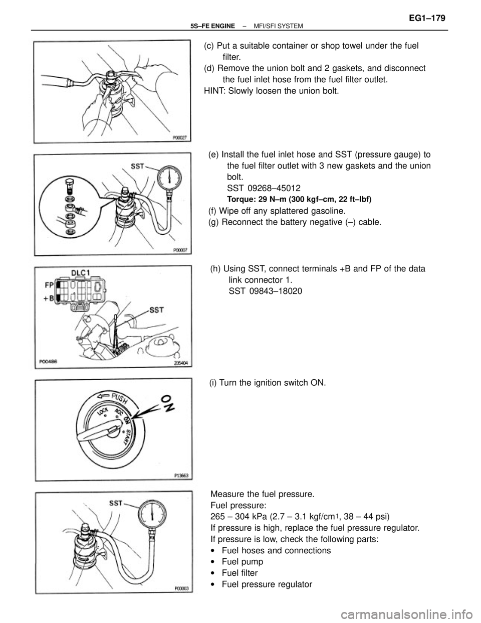
Measure the fuel pressure.
Fuel pressure:
265 ± 304 kPa (2.7 ± 3.1 kgf/cm�, 38 ± 44 psi)
If pressure is high, replace the fuel pressure regulator.
If pressure is low, check the following parts:
wFuel hoses and connections
wFuel pump
wFuel filter
wFuel pressure regulator (e) Install the fuel inlet hose and SST (pressure gauge) to
the fuel filter outlet with 3 new gaskets and the union
bolt.
SST 09268±45012
Torque: 29 N±m (300 kgf±cm, 22 ft±lbf)
(f) Wipe off any splattered gasoline.
(g) Reconnect the battery negative (±) cable. (c) Put a suitable container or shop towel under the fuel
filter.
(d) Remove the union bolt and 2 gaskets, and disconnect
the fuel inlet hose from the fuel filter outlet.
HINT: Slowly loosen the union bolt.
(h) Using SST, connect terminals +B and FP of the data
link connector 1.
SST 09843±18020
(i) Turn the ignition switch ON.
± 5S±FE ENGINEMFI/SFI SYSTEMEG1±179
Page 230 of 4770
 Stop the engine.
(r) Check that the fuel pressure remains 147 kPa (1.5
kgf/cm
2, 21 psi) or more for 5 minutes after the
engine is turned off.
If pressure is not as specified, check the fuel pump,")
(q) Stop the engine.
(r) Check that the fuel pressure remains 147 kPa (1.5
kgf/cm
2, 21 psi) or more for 5 minutes after the
engine is turned off.
If pressure is not as specified, check the fuel pump,
pressure regulator and/or injector.
(s) After checking fuel pressure, disconnect the battery
negative (±) cable and carefully remove the SST to
prevent gasoline from splashing.
SST 09268±45012
(t) Connect the fuel inlet hose with 2 new gaskets and
the union bolt.
Torque: 29 N±m (300 kgf±cm. 22 ft±lbf)
(u) Reconnect the cable to the negative (±) terminal of
the battery.
(v) Check for fuel leakage.(o) Reconnect the vacuum sensing hose to the air intake
chamber.
(p) Measure the fuel pressure at idle.
Fuel pressure:
206 ± 255 kPa (2.1 ± 2.6 kgf/cm�, 31 ± 37 psi)
If pressure is not as specified, check the vacuum
sensing hose and fuel pressure regulator.(l) Start the engine.
(m) Disconnect the vacuum sensing hose from the air
intake chamber and plug the air intake chamber
outlet.
(n) Measure the fuel pressure at idle.
Fuel pressure:
265 ± 304 kPa (2.7 ± 3.1 kgf/cm�, 38 ± 44 psi) (k) Remove the SST.
SST 09483±18020
± 5S±FE ENGINEMFI/SFI SYSTEMEG1±180
Page 231 of 4770
 lead from the battery terminal 4 of the
connector, and the negative (±) lead
to terminal 5. Check that the fuel pump operates.
NOTICE:
wThese t")
B. Inspect fuel pump operation
Connect the positive (+) lead from the battery terminal 4 of the
connector, and the negative (±) lead
to terminal 5. Check that the fuel pump operates.
NOTICE:
wThese tests must be performed quickly (within 10
seconds) to prevent the coil from burning out.
wKeep the fuel pump a: far away from the battery as
possible.
wAlways perform switching at the battery side.
If operation is not as specified, replace the fuel pump.
5. RECONNECT FUEL PUMP & SENDER GAUGE
CONNECTOR
6. INSTALL REAR SEAT CUSHION
7. CONNECT NEGATIVE (±) TERMINAL CABLE TO
BATTERY
FUEL PUMP INSPECTION
1. DISCONNECT NEGATIVE (±) TERMINAL CABLE
FROM BATTERY
CAUTION: Work must be started after 90 seconds from
the time the Ignition switch Is turned to the 'LOCK'
position and the negative (±) terminal cable is discon±
nected from the battery.
4. INSPECT FUEL PUMP
A. Inspect fuel pump resistance
Using an ohmmeter, measure the resistance between
terminals 4 and 5.
Resistance (Cold):
0.2±3.0 W
If the resistance is not as specified, replace the fuel
pump. 2. REMOVE REAR SEAT CUSHION
3. DISCONNECT FUEL PUMP & SENDER GAUGE CON±
NECTOR
± 5S±FE ENGINEMFI/SFI SYSTEMEG1±181
Page 236 of 4770
2. CONNECT FUEL PIPE AND HOSE TO FUEL PUMP
BRACKET
(a) Using SST, connect the outlet pipe to the pump
bracket.
SST 09631±22020
Torque: 28 N±m (285 kgf±cm, 21 ft±lbf)
(b) Connect the return hoses to the pump bracket.
3. CHECK FOR FUEL LEAKAGE
(See page EG1±176)
4. CONNECT FUEL PUMP LEAD WIRE
5. INSTALL FLOOR SERVICE HOLE COVER
(a) Install the service hole cover with the 5 screws.
(b) Connect the fuel pump (with fuel sender gauge)
connector.
FUEL PUMP INSTALLATION
(See Components for Removal and Installation)
1. INSTALL FUEL PUMP BRACKET ASSEMBLY TO
FUEL TANK
(a) Install a new gasket to the pump bracket.
(b) Insert the pump bracket assembly into the fuel tank.
6. INSTALL REAR SEAT CUSHION
7. CONNECT NEGATIVE (±) TERMINAL CABLE TO
BATTERY(c) Install the pump bracket with the 8 screws.
Torque: 3.9 N±m (40 kgf±cm, 35 in.±Ibf)
± 5S±FE ENGINEMFI/SFI SYSTEMEG1±186
Page 238 of 4770
FUEL PRESSURE REGULATOR
INSTALLATION
(See Components for Removal and Installation)
1. INSTALL FUEL PRESSURE REGULATOR
(a) Apply a light coat of gasoline to a new O±ring, and
install it to the pressure regulator.
2. CONNECT FUEL RETURN PIPE TO FUEL PRESSURE
REGULATOR
Install the return pipe with 2 new gaskets and the
union bolt.
Torque: 19 N±m (195 kgf±cm, 14 ft±lbf)
3. REMOVE FUEL PRESSURE REGULATOR
(a) Remove the 2 bolts, and pull out the pressure regula±
tor.
(b) Remove the O±ring from the pressure regulator.
3. CONNECT VACUUM SENSING HOSE TO FUEL
PRESSURE REGULATOR
4. CHECK FOR FUEL LEAKAGE
(See page EG1±176) (b) Install the pressure regulator with the 2 bolts.
Torque: 5.4 N±m (55 kgf±cm, 48 in.±lbf)
± 5S±FE ENGINEMFI/SFI SYSTEMEG1±188
Page 239 of 4770
2. INSPECT INJECTOR RESISTANCE
(a) Disconnect the injector connector.
(b) Using an ohmmeter, measure the resistance between
the terminals.
Resistance:
Approx. 13.8�
If the resistance is not as specified, replace the injector.
(c) Reconnect the injector connector.
ON±VEHICLE INSPECTION
1. INSPECT INJECTOR OPERATION
Check operation sound from each injector.
(a) With the engine running or cranking, use a sound
scope to check that there is normal operating noise in
proportion to engine speed.
(b) If you have no sound scope, you can check the injec±
tor transmission operation with your finger.
If no sound or unusual sound is heard, check the
wiring connector, injector or injection signal from the
ECM.
INJECTOR
± 5S±FE ENGINEMFI/SFI SYSTEMEG1±189
 Using SST; connect terminals +B and FP of the data
link connector 1.
SST 09843±18020
(b) Turn the ignition switch ON.
NOTICE: Do not start the")
 Check that the battery voltages is above 12 volts.
(b) Disconnect the negative (±) terminal cable from the
battery.
CAUTION: Work must be started after 90 seconds from
the")
 Using SST, connect the outlet pipe to the pump
bracket.
SST 09631±22020
Torque: 28 N±m (285 kgf±cm, 21 ft±lbf)
(b) Connect the return hose")

1. INSTALL FUEL PRESSURE REGULATOR
(a) Apply a light coat of gasoline to a new O±ring, and
install it to the pressur")
