Page 198 of 4770
PCV VALVE INSPECTION
1. REMOVE PCV VALVE
2. INSTALL CLEAN HOSE TO PCV VALVE
3. BLOW AIR FROM CYLINDER HEAD SIDE
Check that air passes through easily.
NOTICE: Do not suck air through the valve.
Petroleum substances inside the valve are harmful.
PCV HOSES AND CONNECTIONS
INSPECTION
VISUALLY INSPECT HOSES, CONNECTIONS AND
GASKETS
Check for cracks, leaks or damage. 4. BLOW AIR FROM AIR INTAKE CHAMBER SIDE
Check that air passes through with difficulty.
If the PCV valve fails either of the checks, replace it.
5. REMOVE CLEAN HOSE FROM PCV VALVE
6. REINSTALL PCV VALVE
± 5S±FE ENGINEEMISSION CONTROL SYSTEMSEG1±148
Page 199 of 4770
To reduce NC emissions, evaporated fuel from the fuel tank is routed through the charcoal canister to the intake manifold
for combustion in the cylinders.
EVAPORATIVE EMISSION (EVAP)
CONTROL SYSTEM
NC from tank is absorbed
into the canister
HC from tank is absorbed
into the canister. HC from canister is led
into air intake chamber.
Air is led into the fuel
tank. Positioned above
port P Positioned below
port P Engine Coolant
Temp.Throttle Valve
OpeningEvaporated Fuel (HC)
Above
54
�C (129�F)Canister Check Valve
High pressure
in tank
High vacuum
in tankBelow
35
�C (95�F)Check
Valve In
Cap
CLOSED
CLOSED
CLOSEDCLOSED CLOSED
OPEN
OPEN OPEN OPEN
OPEN TVV
± 5S±FE ENGINEEMISSION CONTROL SYSTEMSEG1±149
Page 200 of 4770
 Using low pressure compressed air (4.71 kPa, 48
gf/cm
2, 0.68 psi), blow into port A and check that air
flows without resistance from the other")
3. CHECK FOR CLOGGED FILTER AND STUCK CHECK
VALVE
(a) Using low pressure compressed air (4.71 kPa, 48
gf/cm
2, 0.68 psi), blow into port A and check that air
flows without resistance from the other ports.
(b) Blow air (4.71 kPa, 48 gf/cm�, 0.68 psi) into port B
and check that air does not flow from the other ports.
If a problem is found, replace the charcoal canister.
4. CLEAN FILTER IN CANISTER
Clean the filter by blowing 294 kPa (3 kgf/cm�, 43 psi)
of compressed air into port A while holding port B
closed.
NOTICE:
wDo not attempt to wash the canister.
wNo activated carbon should come out.
5. REINSTALL CHARCOAL CANISTER
FUEL VAPOR LINES. FUEL TANK AND
TANK CAP INSPECTION
1. VISUALLY INSPECT LINES AND CONNECTIONS
Look for loosen connections, sharp bends or damage.
2. VISUALLY INSPECT FUEL TANK
Look for deformation, cracks or fuel leakage.
CHARCOAL CANISTER INSPECTION
1. REMOVE CHARCOAL CANISTER
2. VISUALLY INSPECT CHARCOAL CANISTER
Look for cracks or damage. 3. VISUALLY INSPECT FUEL TANK CAP
Check if the cap and/or gasket are deformed or dam±
aged.
If necessary, repair or replace the cap.
± 5S±FE ENGINEEMISSION CONTROL SYSTEMSEG1±150
Page 201 of 4770
 Apply adhesive to 2 or 3 threads of the TVV, and
install it.
Adhesive:
Part No. 08833±00070, THREE BOND 1324
or equivalent
Torque: 29 N±m (300 kgf±cm, 22 ft�")
4. REINSTALL TVV
(a) Apply adhesive to 2 or 3 threads of the TVV, and
install it.
Adhesive:
Part No. 08833±00070, THREE BOND 1324
or equivalent
Torque: 29 N±m (300 kgf±cm, 22 ft±lbf)
(b) Reconnect 2 vacuum hoses.
5. REFILL WITH ENGINE COOLANT
CHECK VALVE INSPECTION
INSPECT CHECK VALVE
(a) Check that air flows from the yellow port to the black
port.
(b) Check that air does not flow from the black port to the
yellow port.
If operation is not as specified, replace the check
valve.
TVV INSPECTION
1. DRAIN ENGINE COOLANT
2. REMOVE TVV FROM WATER INLET HOUSING
(a) Disconnect the following hoses:
(1) Vacuum hose (from throttle body)
(2) Vacuum hose (from charcoal canister)
(b) Remove the TVV.
3. INSPECT TVV OPERATION
(a) Cool the TVV to below 35�C (95�F) with cool water.
(b) Check that air does not flow from the upper port to
lower port.
(c) Heat the TVV to above 54�C (129�F) with hot water.
(d) Check that air flows from the upper port to lower port.
If operation is not as specified, replace the TVV.
± 5S±FE ENGINEEMISSION CONTROL SYSTEMSEG1±151
Page 203 of 4770
EGR SYSTEM INSPECTION
1. CHECK AND CLEAN FILTER IN EGR VACUUM
MODULATOR
(a) Check the filter for contamination or damage.
(b) Using compressed air, clean the filter.
HINT: Install the filter with the coarser surface facing
the atmospheric side (outward).
2. PREPARATION
Using a 3±way connector, connect a vacuum gauge
to the hose between the EGR valve and VSV.
3. CHECK SEATING OF EGR VALVE
Start the engine and check that the engine starts and
runs at idle.
6. CHECK VSV AND EGR VACUUM MODULATOR
WITH HOT ENGINE
(a) Warm up the engine.
(b) Check that the vacuum gauge indicates low vacuum
at 2,500 rpm. 5. CHECK VSV
(a) The engine coolant temperature should be below
60�C (140�F) (A/T) or 55�C (131 �F) (M/T).
(b) Check that the vacuum gauge indicates zero at 2.500
rpm. 4. CONNECT TERMINALS TE1 AND E1
Using SST, connect terminals TE 1 and E 1 of the data
link connector 1.
SST 09843±18020
± 5S±FE ENGINEEMISSION CONTROL SYSTEMSEG1±153
Page 204 of 4770

1. REMOVE VSV
(a) Disconnect the following connectors and hoses:
(1) VSV for EGR
(A) connector
(2) VSV for fuel pressure control
(B) connector
(3) Vacuum hose (from EGR val")
VSV INSPECTION (California)
1. REMOVE VSV
(a) Disconnect the following connectors and hoses:
(1) VSV for EGR
(A) connector
(2) VSV for fuel pressure control
(B) connector
(3) Vacuum hose (from EGR valve) from port E of
VSV (A)
(4) Vacuum hose (from port ªaº of EGR vacuum
modulator) from port G of VSV (A)
(5) Vacuum hose (from fuel pressure regulator) from
port E of VSV (B)
(6) Vacuum hose (from air intake chamber) from port
G of VSV (B)
(b) Remove the bolt and VSV assembly. (c) Disconnect the vacuum hose port R of the EGR
vacuum modulator and connect port R directly to the
intake manifold with another hose.
(d) Check that the vacuum gauge indicates high vacuum
at 2,500 rpm.
HINT: As a large amount of exhaust gas enters, the
engine will misfire slightly.
(e) Remove the vacuum gauge, and reconnect the
vacuum hoses to the proper locations.
8. DISCONNECT TERMINALS TE1 AND E1
Remove the SST.
SST 09843±18020
IF NO PROBLEM IS FOUND WITH THIS
INSPECTION, SYSTEM IS NORMAL; OTHERWISE
INSPECT EACH PART 7. CHECK EGR VALVE
(a) Apply vacuum directly to the EGR valve with the
engine idling.
(b) Check that the engine runs rough or dies.
(c) Reconnect the vacuum hoses to the proper locations.
± 5S±FE ENGINEEMISSION CONTROL SYSTEMSEG1±154
Page 205 of 4770
VSV INSPECTION (Except California)
1. REMOVE VSV
(a) Disconnect the following connector and hoses:
(1) VSV connector
(2) Vacuum hose (from EGR valve) from port E of
VSV
(3) Vacuum hose (from port ªQº of EGR vacuum
modulator) from port G of VSV 2. INSPECT VSV
A. Inspect VSV for open circuit
Using an ohmmeter, check that there is continuity
between the terminals.
Resistance (Cold):
33±39�
If there is no continuity, replace the VSV.
B. Inspect VSV for ground
Using an ohmmeter, check that there is no continuity
between each terminal and the body.
If there is continuity, replace the VSV.
(b) Apply battery voltage across the terminals.
(c) Check that air flows from port E to the filter.
If operation is not as specified, replace the VSV.
3. REINSTALL VSVC. Inspect VSV operation
(a) Check that air flows from port E to port G.
± 5S±FE ENGINEEMISSION CONTROL SYSTEMSEG1±155
Page 206 of 4770
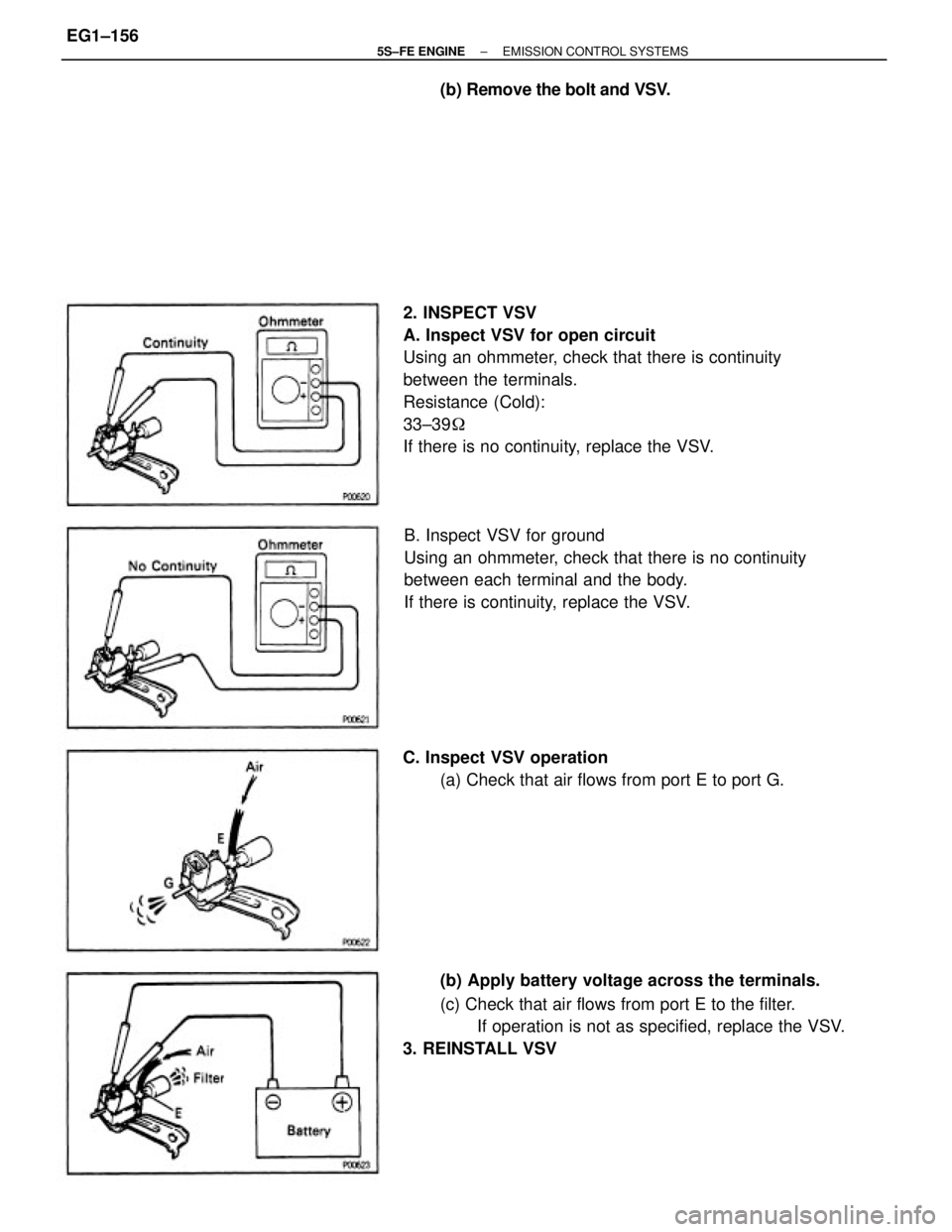
2. INSPECT VSV
A. Inspect VSV for open circuit
Using an ohmmeter, check that there is continuity
between the terminals.
Resistance (Cold):
33±39�
If there is no continuity, replace the VSV.
B. Inspect VSV for ground
Using an ohmmeter, check that there is no continuity
between each terminal and the body.
If there is continuity, replace the VSV.
(b) Apply battery voltage across the terminals.
(c) Check that air flows from port E to the filter.
If operation is not as specified, replace the VSV.
3. REINSTALL VSV C. Inspect VSV operation
(a) Check that air flows from port E to port G. (b) Remove the bolt and VSV.
± 5S±FE ENGINEEMISSION CONTROL SYSTEMSEG1±156


CONTROL SYSTEM
NC")
 Check the filter for contamination or damage.
(b) Using compressed air, clean the filter.
HINT: Install the filter with the")

1. REMOVE VSV
(a) Disconnect the following connector and hoses:
(1) VSV connector
(2) Vacuum hose (from EGR valve) from port E of
VSV
(3) Vacuum hose (from port ªQ�")