Page 207 of 4770
EGR VALVE INSPECTION
1. REMOVE EGR VALVE
Check for sticking and heavy carbon deposits.
If a problem is found, replace the valve.
2. REINSTALL EGR VALVE WITH NEW GASKET
Nut
Torque: 13 N±m (130 kgf±cm, 9 ft±lbf)
Union nut
Torque: 59 N±m (600 kgf±cm, 43 ft±lbf)
EGR VACUUM MODULATOR INSPECTION
CHECK EGR VACUUM MODULATOR OPERATION
(a) Disconnect the vacuum hoses from ports P, Q and R
of the EGR vacuum modulator.
(b) Block ports P and R with your finger.
(c) Blow air into port Q, and check that the air passes
through to the air filter side freely.
(d) Start the engine, and maintain speed at 2.500 rpm.
(e) Repeat the above test. Check that there is a strong
resistance to air flow.
(f) Reconnect the vacuum hoses to the proper locations.
± 5S±FE ENGINEEMISSION CONTROL SYSTEMSEG1±157
Page 208 of 4770
EXHAUST PIPE ASSEMBLY INSPECTION
1. CHECK CONNECTIONS FOR LOOSENESS OR
DAMAGE
2. CHECK CLAMPS FOR WEAKNESS, CRACKS OR
DAMAGE
THREE±WAY CATALYTIC CONVERTER
INSPECTION
TWC:
CHECK FOR DENTS OR DAMAGE
If any part of protector is damaged or dented to the
extent that it contacts the TWC, repair or replace it.
To reduce C0, HC end NOx emissions, they are oxidized, reduced and converted to carbon dioxide (CO2), water (H20)
and nitrogen (N
2) by the catalyst.
THREE±WAY CATALYTIC CONVERTER (TWC) SYSTEM
Exhaust Port
Exhaust Gas WU±TWC
TWC
± 5S±FE ENGINEEMISSION CONTROL SYSTEMSEG1±158
Page 209 of 4770

THREE±WAY CATALYTIC CONVERTER
REPLACEMENT
WU±TWC:
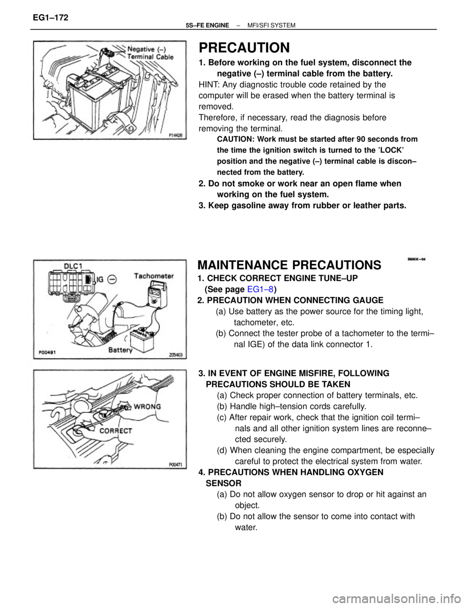
1. DISCONNECT NEGATIVE (±) TERMINAL CABLE
FROM BATTERY
CAUTION: Work must be started after 90 seconds from
the time the ignition switch is turned to the 'LOCK'
position and the negative (±) terminal cable is discon±
nected from the battery.
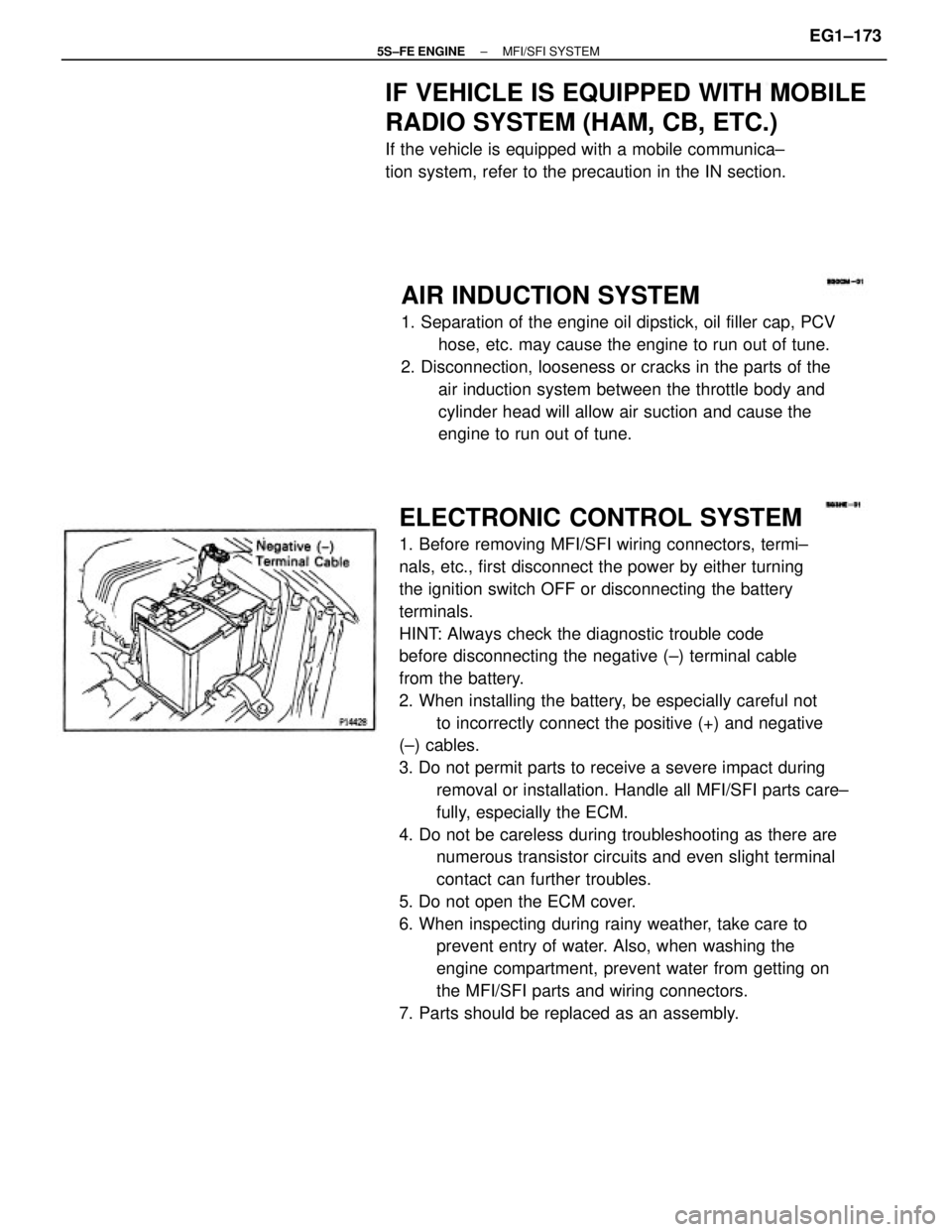
2. REMOVE FRONT EXHAUST PIPE
(a) Loosen the 2 bolts, and disconnect the bracket.
(b) Remove the 2 bolts and nuts holding the front exhaust
pipe to the center exhaust pipe.
(c) Using a 14 mm deep socket wrench, remove the 3
nuts holding the front exhaust pipe to the WU±TWC.
(d) Remove the front exhaust pipe and gaskets.HEAT INSULATOR INSPECTION
TWC:
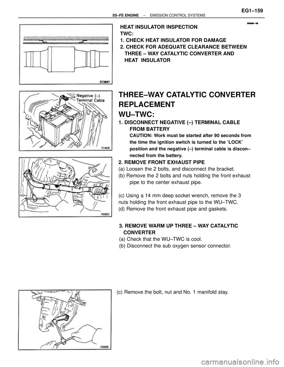
1. CHECK HEAT INSULATOR FOR DAMAGE
2. CHECK FOR ADEQUATE CLEARANCE BETWEEN
THREE ± WAY CATALYTIC CONVERTER AND
HEAT INSULATOR
3. REMOVE WARM UP THREE ± WAY CATALYTIC
CONVERTER
(a) Check that the WU±TWC is cool.
(b) Disconnect the sub oxygen sensor connector.
(c) Remove the bolt, nut and No. 1 manifold stay.
± 5S±FE ENGINEEMISSION CONTROL SYSTEMSEG1±159
Page 220 of 4770
PREPARATION
SST (SPECIAL SERVICE TOOLS)
(90405±09015) No.1 Union (09268±41090) No.7 union (09268±41080) No.6 union
09631±22020 Power Steering Hose Nut
14 x 17 mm Wrench Set
RECOMMENDED TOOLS
Plug for vacuum hose, fuel hose
etc. 09268±41045 Injection Measuring Tool Set
09082±00050 TOYOTA Electrical Tester Set 09842±30070 Wiring ªFº EFI Inspection 09268±45012 EFI Fuel Pressure Gauge
09843±18020 Diagnosis Check Wire
09200±00010 Engine Adjust Kit
09258±00030 Hose Plug SetFuel line flare nut
± 5S±FE ENGINEMFI/SFI SYSTEMEG1±170
Page 222 of 4770

PRECAUTION
1. Before working on the fuel system, disconnect the
negative (±) terminal cable from the battery.
HINT: Any diagnostic trouble code retained by the
computer will be erased when the battery terminal is
removed.
Therefore, if necessary, read the diagnosis before
removing the terminal.
CAUTION: Work must be started after 90 seconds from
the time the ignition switch is turned to the 'LOCK'
position and the negative (±) terminal cable is discon±
nected from the battery.
2. Do not smoke or work near an open flame when
working on the fuel system.
3. Keep gasoline away from rubber or leather parts.
3. IN EVENT OF ENGINE MISFIRE, FOLLOWING
PRECAUTIONS SHOULD BE TAKEN
(a) Check proper connection of battery terminals, etc.
(b) Handle high±tension cords carefully.
(c) After repair work, check that the ignition coil termi±
nals and all other ignition system lines are reconne±
cted securely.
(d) When cleaning the engine compartment, be especially
careful to protect the electrical system from water.
4. PRECAUTIONS WHEN HANDLING OXYGEN
SENSOR
(a) Do not allow oxygen sensor to drop or hit against an
object.
(b) Do not allow the sensor to come into contact with
water.
MAINTENANCE PRECAUTIONS
1. CHECK CORRECT ENGINE TUNE±UP
(See page EG1±8)
2. PRECAUTION WHEN CONNECTING GAUGE
(a) Use battery as the power source for the timing light,
tachometer, etc.
(b) Connect the tester probe of a tachometer to the termi±
nal IGE) of the data link connector 1.
± 5S±FE ENGINEMFI/SFI SYSTEMEG1±172
Page 223 of 4770

ELECTRONIC CONTROL SYSTEM
1. Before removing MFI/SFI wiring connectors, termi±
nals, etc., first disconnect the power by either turning
the ignition switch OFF or disconnecting the battery
terminals.
HINT: Always check the diagnostic trouble code
before disconnecting the negative (±) terminal cable
from the battery.
2. When installing the battery, be especially careful not
to incorrectly connect the positive (+) and negative
(±) cables.
3. Do not permit parts to receive a severe impact during
removal or installation. Handle all MFI/SFI parts care±
fully, especially the ECM.
4. Do not be careless during troubleshooting as there are
numerous transistor circuits and even slight terminal
contact can further troubles.
5. Do not open the ECM cover.
6. When inspecting during rainy weather, take care to
prevent entry of water. Also, when washing the
engine compartment, prevent water from getting on
the MFI/SFI parts and wiring connectors.
7. Parts should be replaced as an assembly.
AIR INDUCTION SYSTEM
1. Separation of the engine oil dipstick, oil filler cap, PCV
hose, etc. may cause the engine to run out of tune.
2. Disconnection, looseness or cracks in the parts of the
air induction system between the throttle body and
cylinder head will allow air suction and cause the
engine to run out of tune.
IF VEHICLE IS EQUIPPED WITH MOBILE
RADIO SYSTEM (HAM, CB, ETC.)
If the vehicle is equipped with a mobile communica±
tion system, refer to the precaution in the IN section.
± 5S±FE ENGINEMFI/SFI SYSTEMEG1±173
Page 224 of 4770
(b) Insert the test probe into the connector from wiring
side when checking the continuity, amperage or volt±
age.
(c) Do not apply unnecessary force to the terminal.
(d) After checking, install the water±proofing rubber on
the connector securely. 8. Care is required when pulling out and inserting wiring
connectors.
(a) Release the lock and pull out the connector, pulling on
the connectors.
9. When inspecting a connector with a volt/ohmmeter.
(a) Carefully take out the water±proofing rubber if it is a
water±proof type connector.
10. Use SST for inspection or test of the injector or its
wiring connector.
SST 09842±30070 (b) Fully insert the connector and check that it is locked.
± 5S±FE ENGINEMFI/SFI SYSTEMEG1±174
Page 226 of 4770
5. Check that there are no fuel leaks after performing
maintenance anywhere on the fuel system.
(a) Using SST, connect terminals + B and FP of the data
link connector 1.
SST 09843±18020
(b) With engine stopped, turn the ignition switch ON.
(c) Pinch the fuel return hose. The pressure in high pres±
sure line will rise to approx. 392 kPa (4kgf/cm2, 57
psi). In this state, check to see that there are no leaks
from any part of the fuel system.
NOTICE: Always pinch the hose. Avoid bending as it may
cause the hose to crack.
(d) Turn the ignition switch OFF.
(9) Remove the SST.
SST 09843±18020
± 5S±FE ENGINEMFI/SFI SYSTEMEG1±176