Page 118 of 4770
2. INSTALL SPARK PLUG TUBES
(a) Clean the cylinder head tube holes of any residua!
adhesive, oil or foreign particles. Remove any oil with
kerosene or gasoline.
(b) Screw the threads of the spark plug tube coated with
adhesive into the cylinder head.
(c) Using the spark plug tube nut and a 30 mm socket
wrench, tighten the spark plug tubes.
Torque: 39 N±m (400 kgf±cm, 29 ft±lbf)
(b) Install the following parts:
(1) Camshaft gear spring
(2) Camshaft sub gear
(3) Wave washer
HINT: Align the pins on the gears with the spring ends.(d) Retighten the cylinder head bolts 90� in the sequence
shown on the previous page.
(e) Check that the painted mark is now at a 90� angle to
front.
3. ASSEMBLY EXHAUST CAMSHAFT
(a) Mount the hexagon wrench head portion of the cam±
shaft in a vise.
NOTICE: Be careful not to damage the camshaft.
(c) Mark the front of the cylinder head bolt head with
paint.
± 5S±FE ENGINEENGINE MECHANICALEG1±68
Page 121 of 4770

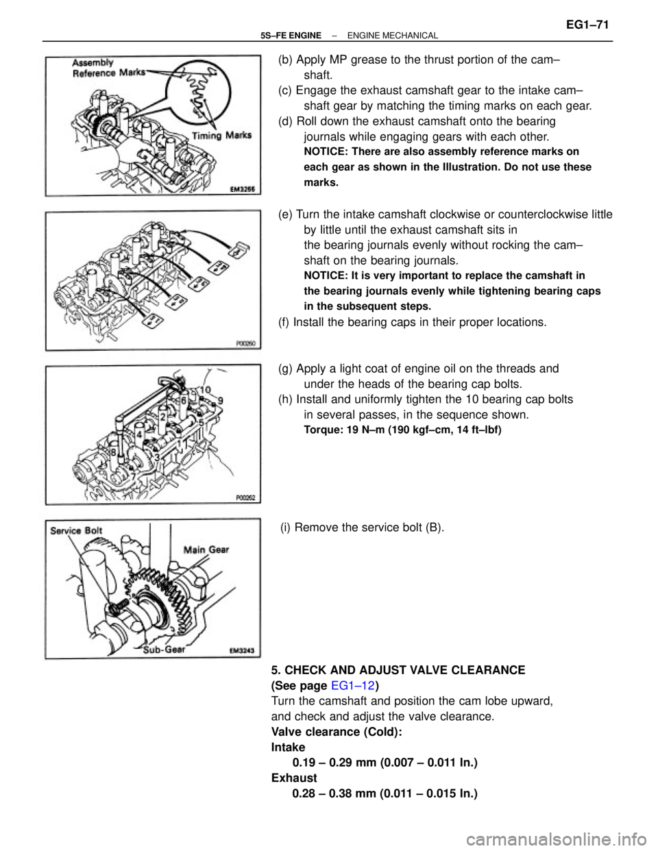
(b) Apply MP grease to the thrust portion of the cam±
shaft.
(c) Engage the exhaust camshaft gear to the intake cam±
shaft gear by matching the timing marks on each gear.
(d) Roll down the exhaust camshaft onto the bearing
journals while engaging gears with each other.
NOTICE: There are also assembly reference marks on
each gear as shown in the Illustration. Do not use these
marks.
5. CHECK AND ADJUST VALVE CLEARANCE
(See page EG1±12)
Turn the camshaft and position the cam lobe upward,
and check and adjust the valve clearance.
Valve clearance (Cold):
Intake
0.19 ± 0.29 mm (0.007 ± 0.011 In.)
Exhaust
0.28 ± 0.38 mm (0.011 ± 0.015 In.)(e) Turn the intake camshaft clockwise or counterclockwise little
by little until the exhaust camshaft sits in
the bearing journals evenly without rocking the cam±
shaft on the bearing journals.
NOTICE: It is very important to replace the camshaft in
the bearing journals evenly while tightening bearing caps
in the subsequent steps.
(f) Install the bearing caps in their proper locations.
(g) Apply a light coat of engine oil on the threads and
under the heads of the bearing cap bolts.
(h) Install and uniformly tighten the 10 bearing cap bolts
in several passes, in the sequence shown.
Torque: 19 N±m (190 kgf±cm, 14 ft±lbf)
(i) Remove the service bolt (B).
± 5S±FE ENGINEENGINE MECHANICALEG1±71
Page 124 of 4770
13. TEMPORARILY INSTALL NO.1 IDLER PULLEY AND
TENSION SPRING
(a) Install the pulley with the bolt. Do not tighten the bolt
yet.
HINT: Use bolt 42 mm (1.65 in.) in length.
(b) Install the tension spring.
(c) Pry the pulley toward the left as far as it will go and
tighten the bolt.
(d) Check that the idler pulley moves smoothly.
14. INSTALL CAMSHAFT TIMING PULLEY AND
TIMING BELT
(See page EG1±33)
15. INSTALL INJECTORS AND DELIVERY PIPE
(a) California:
Install new insulator and grommet to each injector.
(b) Except California:
Install a new grommet to each injector.
(c) California:
Apply a light coat of gasoline to 2 new 0±rings, and
install them to each injector.
(d) Except California:
Apply a light coat of gasoline to a new 0±ring, and
install it to each injector.
(e) While turning the injector left and right, install it to the
delivery pipes. Install the 4 injectors.
± 5S±FE ENGINEENGINE MECHANICALEG1±74
Page 125 of 4770
(i) Check that the injectors rotate smoothly.
HINT: If injectors do not rotate smoothly, the probable
cause is incorrect installation of O±rings. Replace the
O±rings.
(j) Position the injector connector upward. (g) Place the 4 injectors together with the delivery pipe in
position on the cylinder head.
(h) Temporarily install the 2 bolts holding the delivery
pipe to the cylinder head.
(l) Connect the fuel return hose.
(m) Connect the fuel inlet pipe to the delivery pipe with 2 new
gaskets and the pulsation damper.
Torque: 34 N±m (350 kgf±cm, 25 ft±lbf)
(f) Install the following parts to the intake manifold:
(1) 2 spacers
(2) Except California:
4 new insulators
(k) Tighten the 2 bolts holding the delivery pipe to the
cylinder head.
Torque: 13 N±m (130 kgf±cm, 9 ft±lbf)
± 5S±FE ENGINEENGINE MECHANICALEG1±75
Page 132 of 4770
37. A/T:
CONNECT AND ADJUST THROTTLE CABLE
38. CONNECT AND ADJUST ACCELERATOR CABLE
39. FILL WITH ENGINE COOLANT
Capacity:
6.3 liters (6.7 US qts, 5.5 Imp. qts)
40. CONNECT NEGATIVE (±) TERMINAL CABLE TO
BATTERY
41. START ENGINE AND CHECK FOR LEAKS
42. ADJUST IGNITION TIMING
(See page IG ±19 and 38)
Ignition timing:
10� BTDC @ idle
(w/ Terminals TO and E1 connected)
43. PERFORM ROAD TEST
Check for abnormal noise, shock, slippage, correct shift
points and smooth operation.
44. RECHECK ENGINE COOLANT LEVEL AND OIL
LEVEL
± 5S±FE ENGINEENGINE MECHANICALEG1±82
Page 144 of 4770

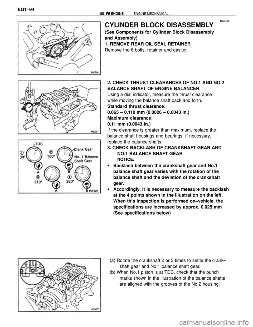
2. CHECK THRUST CLEARANCES OF NO.1 AND NO.2
BALANCE SHAFT OF ENGINE BALANCER
Using a dial indicator, measure the thrust clearance
while moving the balance shaft back and forth.
Standard thrust clearance:
0.065 ± 0.110 mm (0.0026 ± 0.0043 in.)
Maximum clearance:
0.11 mm (0.0043 in.)
If the clearance is greater than maximum, replace the
balance shaft housings and bearings. If necessary,
replace the balance shafts.
3. CHECK BACKLASH OF CRANKSHAFT GEAR AND
NO.1 BALANCE SHAFT GEAR
NOTICE:
wBacklash between the crankshaft gear and No.1
balance shaft gear varies with the rotation of the
balance shaft and the deviation of the crankshaft
gear.
wAccordingly, it is necessary to measure the backlash
at the 4 points shown in the illustration on the left.
When this inspection is performed on±vehicle, the
specifications are increased by approx. 0.025 mm
(See specifications below)
CYLINDER BLOCK DISASSEMBLY
(See Components for Cylinder Block Disassembly
and Assembly)
1. REMOVE REAR OIL SEAL RETAINER
Remove the 6 bolts, retainer and gasket.
(a) Rotate the crankshaft 2 or 3 times to settle the crank±
shaft gear and No.1 balance shaft gear.
(b) When No.1 piston is at TDC, check that the punch
marks shown in the illustration of the balance shafts
are aligned with the grooves of the No.2 housing.
± 5S±FE ENGINEENGINE MECHANICALEG1±94
Page 145 of 4770

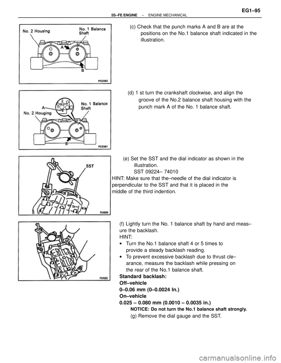
(f) Lightly turn the No. 1 balance shaft by hand and meas±
ure the backlash.
HINT:
wTurn the No.1 balance shaft 4 or 5 times to
provide a steady backlash reading.
wTo prevent excessive backlash due to thrust cle±
arance, measure the backlash while pressing on
the rear of the No.1 balance shaft.
Standard backlash:
Off±vehicle
0±0.06 mm (0±0.0024 In.)
On±vehicle
0.025 ± 0.080 mm (0.0010 ± 0.0035 in.)
NOTICE: Do not turn the No.1 balance shaft strongly.
(g) Remove the dial gauge and the SST. (e) Set the SST and the dial indicator as shown in the
illustration.
SST 09224± 74010
HINT: Make sure that the±needle of the dial indicator is
perpendicular to the SST and that it is placed in the
middle of the third indention.(d) 1 st turn the crankshaft clockwise, and align the
groove of the No.2 balance shaft housing with the
punch mark A of the No. 1 balance shaft. (c) Check that the punch marks A and B are at the
positions on the No.1 balance shaft indicated in the
illustration.
± 5S±FE ENGINEENGINE MECHANICALEG1±95
Page 148 of 4770
5. CHECK CONNECTING ROD THRUST CLEARANCE
Using a dial indicator, measure the thrust clearance
while moving the connecting rod back and forth.
Standard thrust clearance:
0.160 ± 0.312 mm (0.0063 ± 0.0123 in.)
Maximum thrust clearance:
0.36 mm (0.0138 in.)
If the thrust clearance is greater than maximum, re±
place the connecting rod assembly. If necessary, re±
place the crankshaft.
6. REMOVE CONNECTING ROD CAPS AND CHECK
OIL CLEARANCE
(a) Check the matchmarks on the connecting rod and cap
to ensure correct reassembly.
(c) Using a plastic±faced hammer, lightly tap the con±
necting rod bolts and lift off the connecting rod cap.
HINT: Keep the lower bearing inserted with the con±
necting rod cap.4. REMOVE ENGINE BALANCER
(a) Uniformly loosen and remove the 6 bolts in several
passes, in the sequence shown.
(b) Remove the engine balancer and spacers.
(b) Using SST, remove the connecting rod cap nuts.
SST 09011±38121
± 5S±FE ENGINEENGINE MECHANICALEG1±98