Page 165 of 4770

CRANKSHAFT INSPECTION AND REPAIR
1. INSPECT CRANKSHAFT FOR RUNOUT
(a) Place the crankshaft on V±blocks.
(b) Using a dial indicator, measure the circle runout at the
center journal.
Maximum circle runout:
0.06 mm (0.0024 In.)
If the circle runout is greater than maximum, replace
the crankshaft.
2. INSPECT MAIN JOURNALS AND CRANK PINS
(a) Using a micrometer, measure the diameter of each
main journal and crank pin.
Main journal diameter:
STD size
54.988 ± 55.003 mm (2.1653±2.1655 in.)
U/S 0.25
54.745 ± 54.755 mm (2.1553±2.1557 in.)
Crank pin diameter:
STD size
51.985 ± 52.000 mm (2.0466±2.0472 in.)
U/S 0.25
51.745 ± 51.755 mm (2.0372±2.0376 in.)
If the diameter is not as specified, check the oil clear±
ance (See pages EG1±98 to 104). If necessary, grind
or replace the crankshaft.
(b) Check each main journal and crank pin for taper and
out±of±round as shown.
Maximum taper and out±of±round:
0.02 mm (0.0008 in.)
If the taper and out±of±round is greater than maxi±
mum, replace the crankshaft.
3. IF NECESSARY. GRIND AND HONE MAIN JOUR±
NALS AND/OR CRANK PINS
Grind and hone the main journals and/or crank pins to
the finished undersized diameter (See procedure in
step 2).
Install new main journal and/or crankshaft pin under±
sized bearings.
± 5S±FE ENGINEENGINE MECHANICALEG1±115
Page 171 of 4770

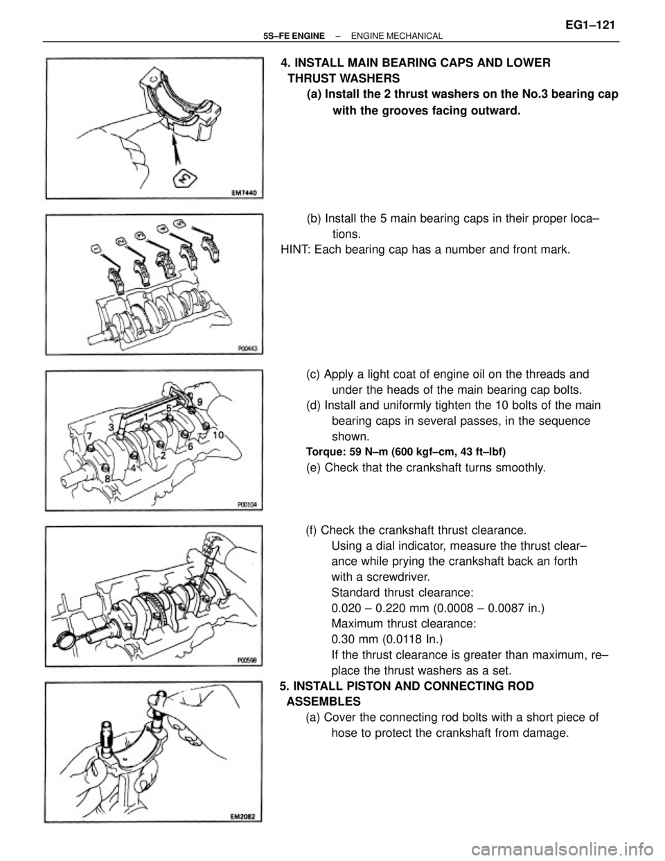
(f) Check the crankshaft thrust clearance.
Using a dial indicator, measure the thrust clear±
ance while prying the crankshaft back an forth
with a screwdriver.
Standard thrust clearance:
0.020 ± 0.220 mm (0.0008 ± 0.0087 in.)
Maximum thrust clearance:
0.30 mm (0.0118 In.)
If the thrust clearance is greater than maximum, re±
place the thrust washers as a set.
5. INSTALL PISTON AND CONNECTING ROD
ASSEMBLES
(a) Cover the connecting rod bolts with a short piece of
hose to protect the crankshaft from damage. (c) Apply a light coat of engine oil on the threads and
under the heads of the main bearing cap bolts.
(d) Install and uniformly tighten the 10 bolts of the main
bearing caps in several passes, in the sequence
shown.
Torque: 59 N±m (600 kgf±cm, 43 ft±lbf)
(e) Check that the crankshaft turns smoothly. 4. INSTALL MAIN BEARING CAPS AND LOWER
THRUST WASHERS
(a) Install the 2 thrust washers on the No.3 bearing cap
with the grooves facing outward.
(b) Install the 5 main bearing caps in their proper loca±
tions.
HINT: Each bearing cap has a number and front mark.
± 5S±FE ENGINEENGINE MECHANICALEG1±121
Page 173 of 4770
(g) Check the connecting rod thrust clearance.
Using a dial indicator, measure the thrust clear±
ance while moving the connecting rod back an
forth.
Standard thrust clearance:
0.160 ± 0.312 mm (0.0063 ± 0.0123 In.)
Maximum thrust clearance:
0.35 mm 10.0138 In.)
If the thrust clearance is greater than maximum, re±
place the connecting rod assembly. If necessary, re±
place the crankshaft. (d) Retighten the cap nuts 90� as shown.
(e) Check that the painted mark is now at a 90� angle to
the front.
(f) Check that the crankshaft turns smoothly.
7. INSTALL ENGINE BALANCER
(a) Turn the crankshaft, and set the No. 1 cylinder TDC as
shown in the illustration.
(b) Set the balance shafts so that the punch marks of the
balance shafts are aligned with the grooves of the
No.
2 housing.
± 5S±FE ENGINEENGINE MECHANICALEG1±123
Page 174 of 4770
(h) Recheck that the punch marks of the balance shafts
are aligned with the grooves of No.2 housing.
8. CHECK AND ADJUST BACKLASH OF
CRANKSHAFT GEAR AND NO.1 BALANCE SHAFT
GEAR (See page EG1±94) (c) Wipe clean the installation surface of the spacer.
(d) Place the spacers on the cylinder block.
HINT: When replacing the crankshaft and/or balance
shaft, use the thickest spacers.
(e) Place the engine balancer on the cylinder block.
(f) Check that punch marks shown in the illustration of
the balance shafts are align with the grooves of the
No.2 housing.
(g) While pulling the center part of the engine balancer
in the direction of the arrow, uniformly tighten the
6
bolts in several passes, in the sequence shown.
Torque: 49 N±m (500 kgf±cm, 36 ft±lbf)
9. INSTALL REAR OIL SEAL RETAINER
Install a new gasket and the retainer with the 6 bolts.
Torque: 9.3 N±m (95 kgf±cm, 82 in.±lbf)
± 5S±FE ENGINEENGINE MECHANICALEG1±124
Page 183 of 4770

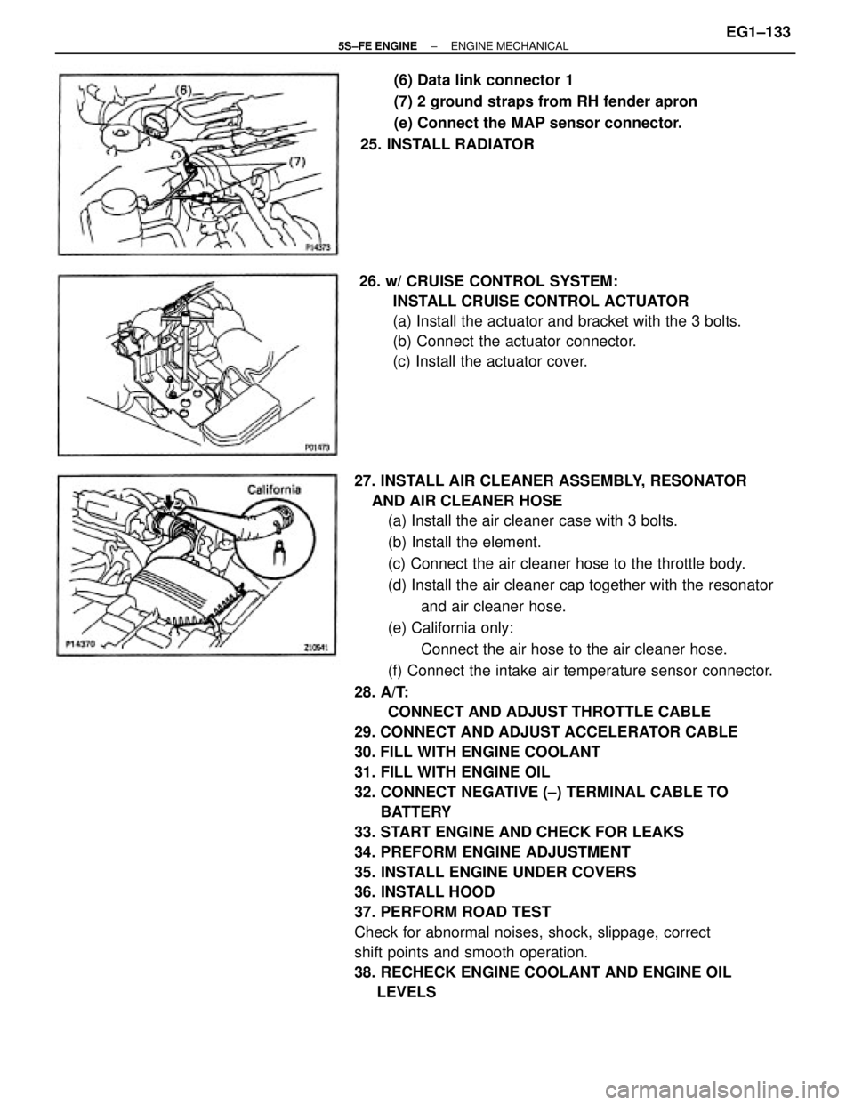
27. INSTALL AIR CLEANER ASSEMBLY, RESONATOR
AND AIR CLEANER HOSE
(a) Install the air cleaner case with 3 bolts.
(b) Install the element.
(c) Connect the air cleaner hose to the throttle body.
(d) Install the air cleaner cap together with the resonator
and air cleaner hose.
(e) California only:
Connect the air hose to the air cleaner hose.
(f) Connect the intake air temperature sensor connector.
28. A/T:
CONNECT AND ADJUST THROTTLE CABLE
29. CONNECT AND ADJUST ACCELERATOR CABLE
30. FILL WITH ENGINE COOLANT
31. FILL WITH ENGINE OIL
32. CONNECT NEGATIVE (±) TERMINAL CABLE TO
BATTERY
33. START ENGINE AND CHECK FOR LEAKS
34. PREFORM ENGINE ADJUSTMENT
35. INSTALL ENGINE UNDER COVERS
36. INSTALL HOOD
37. PERFORM ROAD TEST
Check for abnormal noises, shock, slippage, correct
shift points and smooth operation.
38. RECHECK ENGINE COOLANT AND ENGINE OIL
LEVELS26. w/ CRUISE CONTROL SYSTEM:
INSTALL CRUISE CONTROL ACTUATOR
(a) Install the actuator and bracket with the 3 bolts.
(b) Connect the actuator connector.
(c) Install the actuator cover.(6) Data link connector 1
(7) 2 ground straps from RH fender apron
(e) Connect the MAP sensor connector.
25. INSTALL RADIATOR
± 5S±FE ENGINEENGINE MECHANICALEG1±133
Page 184 of 4770
BALANCE SHAFT BACKLASH
ADJUSTMENT ON VEHICLE
1. CHECK BACKLASH OF CRANKSHAFT GEAR AND
NO.1 BALANCE SHAFT GEAR
NOTICE: Backlash between the crankshaft gear and No.1
balance shaft gear varies with the rotation of the balance
shaft and the deviation of the crankshaft gear.
Accordingly, it is necessary to measure the backlash at
the 4 points shown in the illustration on the left.
(a) Rotate the crankshaft 2 or 3 times to settle the crank±
shaft gear and No. 1 balance shaft gear.
(b) When No.1 piston is at TDC, check that the punch
marks C shown in the illustration of the balance shafts
are aligned with the grooves of the No. 2 housing.
(d) First turn the crankshaft clockwise, and align the
groove of the No.2 balance shaft housing with the
punch mark A of the No. 1 balance shaft. (c) Check that the punch marks A and B are at the
positions on the No.1 balance shaft indicated in the
illustration.
± 5S±FE ENGINEENGINE MECHANICALEG1±134
Page 188 of 4770
3. TORQUE BALANCESHAFT ASSEMBLY
While pulling the center part of the engine balancer in
the direction of the arrow, uniformly tighten the6
bolts in several passes, in the sequence shown.
Torque: 49 N±m (500 kgf±cm, 36 ft±lbf)
4. CHECK AND ADJUST BACKLASH OF CRANK±
SHAFT GEAR AND No.1 BALANCE SHAFT GEAR
(See procedure in step 1) 2. REPLACE THE SPACERS
(a) Uniformly loosen the6 bolts in the sequence shown.
(b) Replace the spacers with new ones.
± 5S±FE ENGINEENGINE MECHANICALEG1±138
Page 195 of 4770
Reduces blow±by gas (HC)
Reduces evaporative HC
Reduces NOx
Reduces C0, HC and NOx
Regulates all engine conditions for reduction
of exhaust emissions. Positive crankcase ventilation
Fuel evaporative emission control
Exhaust gas recirculation
Three±way catalytic converter
*Multiport fuel injection/Sequential
multiport fuel injection
PREPARATION
SST (SPECIAL SERVICE TOOLS)
EMISSION CONTROL SYSTEMS
º For inspection and repair of the MFI/SFI system, refer to MFI/SFI Section.
SSM (SPECIAL SERVICE MATERIALS)
08833±00070 Adhesive 1311,
THREE BOND 1311 or equivalent
RECOMMENDED TOOLS
SYSTEM PURPOSE
09082±00050 TOYOTA Electrical Tester SetPCV
EVAP
EG R
TWC
MFI/SFI
09843±18020 Diagnosis Check Wire
EQUIPMENT
Torque wrench
Vacuum gaugeAbbreviation
Thermometer
Tachometer
Purpose
system
Heater
¿¿VTVV
TVV
± 5S±FE ENGINEEMISSION CONTROL SYSTEMSEG1±145