2000 NISSAN PATROL belt
[x] Cancel search: beltPage 976 of 1033
Description
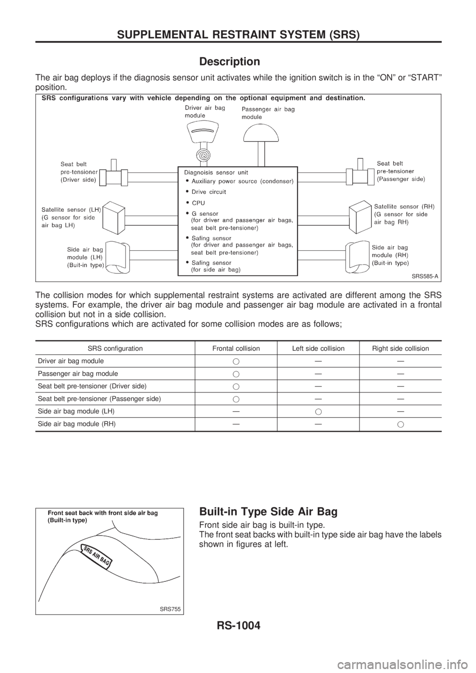
The air bag deploys if the diagnosis sensor unit activates while the ignition switch is in the ªONº or ªSTARTº
position.
The collision modes for which supplemental restraint systems are activated are different among the SRS
systems. For example, the driver air bag module and passenger air bag module are activated in a frontal
collision but not in a side collision.
SRS configurations which are activated for some collision modes are as follows;
SRS configuration Frontal collision Left side collision Right side collision
Driver air bag modulejÐÐ
Passenger air bag modulejÐÐ
Seat belt pre-tensioner (Driver side)jÐÐ
Seat belt pre-tensioner (Passenger side)jÐÐ
Side air bag module (LH) ÐjÐ
Side air bag module (RH) Ð Ðj
Built-in Type Side Air Bag
Front side air bag is built-in type.
The front seat backs with built-in type side air bag have the labels
shown in figures at left.
SRS585-A
SRS755
SUPPLEMENTAL RESTRAINT SYSTEM (SRS)
RS-1004
Page 977 of 1033
Seat Belt Pre-tensioner with Load Limiter
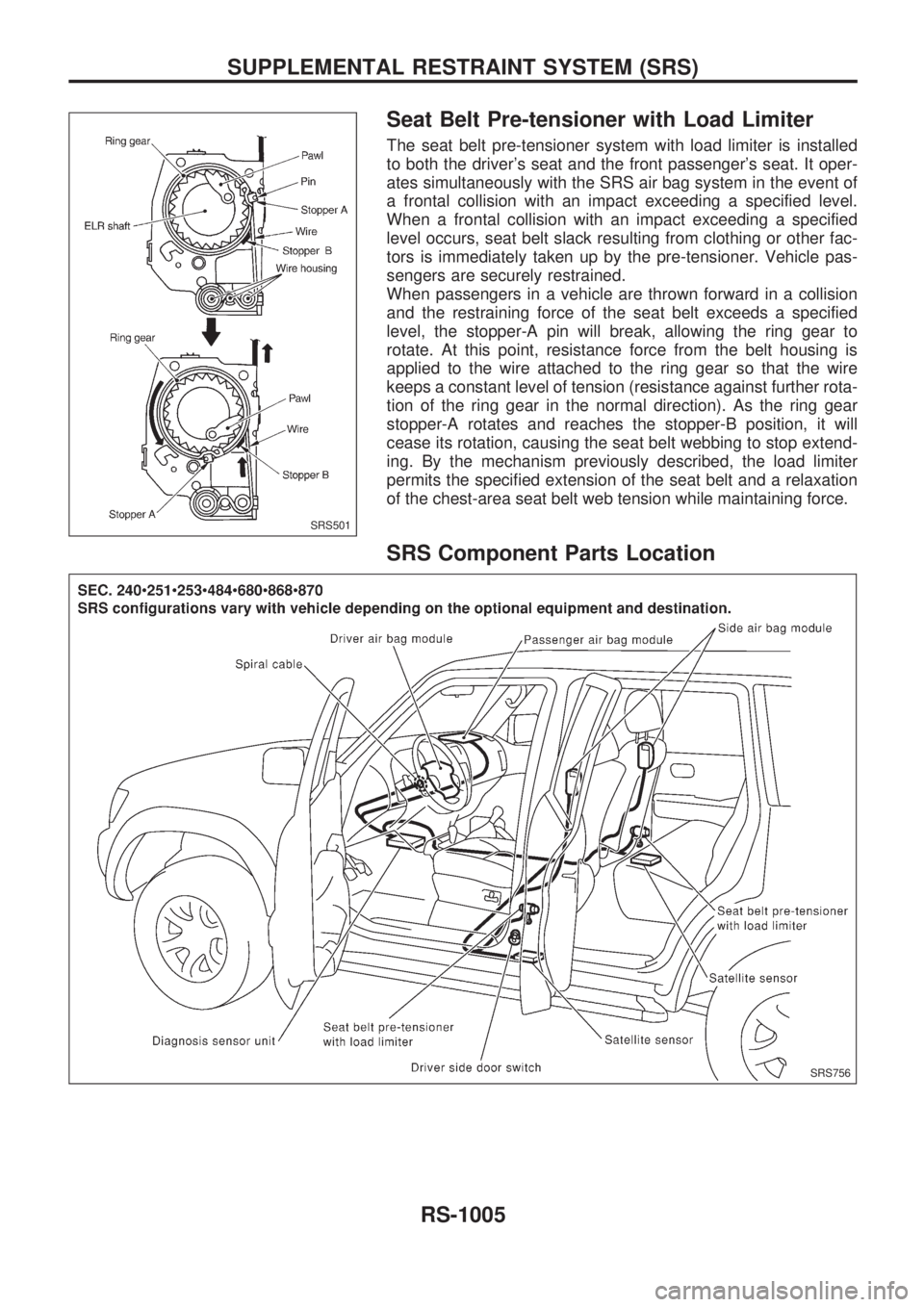
The seat belt pre-tensioner system with load limiter is installed
to both the driver's seat and the front passenger's seat. It oper-
ates simultaneously with the SRS air bag system in the event of
a frontal collision with an impact exceeding a specified level.
When a frontal collision with an impact exceeding a specified
level occurs, seat belt slack resulting from clothing or other fac-
tors is immediately taken up by the pre-tensioner. Vehicle pas-
sengers are securely restrained.
When passengers in a vehicle are thrown forward in a collision
and the restraining force of the seat belt exceeds a specified
level, the stopper-A pin will break, allowing the ring gear to
rotate. At this point, resistance force from the belt housing is
applied to the wire attached to the ring gear so that the wire
keeps a constant level of tension (resistance against further rota-
tion of the ring gear in the normal direction). As the ring gear
stopper-A rotates and reaches the stopper-B position, it will
cease its rotation, causing the seat belt webbing to stop extend-
ing. By the mechanism previously described, the load limiter
permits the specified extension of the seat belt and a relaxation
of the chest-area seat belt web tension while maintaining force.
SRS Component Parts Location
SRS501
SRS756
SUPPLEMENTAL RESTRAINT SYSTEM (SRS)
RS-1005
Page 978 of 1033
Maintenance Items
CAUTION:
Do not use electrical test equipment to check SRS circuit.
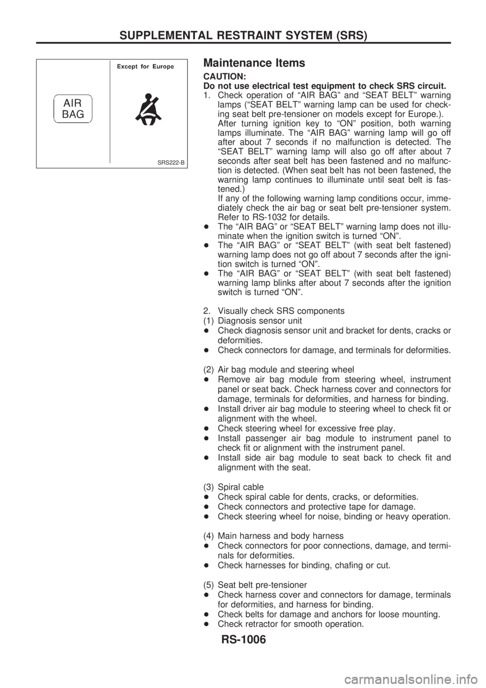
1. Check operation of ªAIR BAGº and ªSEAT BELTº warning
lamps (ªSEAT BELTº warning lamp can be used for check-
ing seat belt pre-tensioner on models except for Europe.).
After turning ignition key to ªONº position, both warning
lamps illuminate. The ªAIR BAGº warning lamp will go off
after about 7 seconds if no malfunction is detected. The
ªSEAT BELTº warning lamp will also go off after about 7
seconds after seat belt has been fastened and no malfunc-
tion is detected. (When seat belt has not been fastened, the
warning lamp continues to illuminate until seat belt is fas-
tened.)
If any of the following warning lamp conditions occur, imme-
diately check the air bag or seat belt pre-tensioner system.
Refer to RS-1032 for details.
+The ªAIR BAGº or ªSEAT BELTº warning lamp does not illu-
minate when the ignition switch is turned ªONº.
+The ªAIR BAGº or ªSEAT BELTº (with seat belt fastened)
warning lamp does not go off about 7 seconds after the igni-
tion switch is turned ªONº.
+The ªAIR BAGº or ªSEAT BELTº (with seat belt fastened)
warning lamp blinks after about 7 seconds after the ignition
switch is turned ªONº.
2. Visually check SRS components
(1) Diagnosis sensor unit
+Check diagnosis sensor unit and bracket for dents, cracks or
deformities.
+Check connectors for damage, and terminals for deformities.
(2) Air bag module and steering wheel
+Remove air bag module from steering wheel, instrument
panel or seat back. Check harness cover and connectors for
damage, terminals for deformities, and harness for binding.
+Install driver air bag module to steering wheel to check fit or
alignment with the wheel.
+Check steering wheel for excessive free play.
+Install passenger air bag module to instrument panel to
check fit or alignment with the instrument panel.
+Install side air bag module to seat back to check fit and
alignment with the seat.
(3) Spiral cable
+Check spiral cable for dents, cracks, or deformities.
+Check connectors and protective tape for damage.
+Check steering wheel for noise, binding or heavy operation.
(4) Main harness and body harness
+Check connectors for poor connections, damage, and termi-
nals for deformities.
+Check harnesses for binding, chafing or cut.
(5) Seat belt pre-tensioner
+Check harness cover and connectors for damage, terminals
for deformities, and harness for binding.
+Check belts for damage and anchors for loose mounting.
+Check retractor for smooth operation.
SRS222-B
SUPPLEMENTAL RESTRAINT SYSTEM (SRS)
RS-1006
Page 979 of 1033
+Perform self-diagnosis for seat belt pre-tensioner using seat
belt warning lamp or CONSULT-II. Refer to ªSelf-diagnosisº
for details.
(6) Satellite sensor
+Check satellite sensor (including bracket portion) for dents,
cracks or deformities.
+Check connectors for damage, and terminals for deformities.
CAUTION:
Replace previously used special bolts, ground bolt and nuts
coated with bonding agent.
SUPPLEMENTAL RESTRAINT SYSTEM (SRS)
Maintenance Items (Cont'd)
RS-1007
Page 980 of 1033
Removal and Installation Ð Diagnosis
Sensor Unit, Seat Belt Pre-tensioner with
Load Limiter and Satellite Sensor
CAUTION:
+Before servicing SRS, turn the ignition switch off, disconnect both battery cables and wait at least
3 minutes.
+Do not use old bolts and nuts coated with bonding agent after removal; replace with new ones.
+Check diagnosis sensor unit, seat belt pre-tensioner with load limiter and satellite sensor for
proper installation.
+Check diagnosis sensor unit and satellite sensor to ensure they are free of deformities, dents,
cracks or rust. If they show any visible signs of damage, replace them with new ones.
+Check diagnosis sensor unit brackets to ensure they are free of deformities and rust.
+After replacement of diagnosis sensor unit, seat belt pre-tensioner and satellite sensor, check
SRS function and perform self-diagnosis for SRS. Refer to ªSelf-diagnosisº for details. (RS-1032)
+Do not attempt to disassemble diagnosis sensor unit, seat belt pre-tensioner with load limiter and
satellite sensor.
+Replace diagnosis sensor unit, seat belt pre-tensioner and satellite sensor if it has been dropped
or sustained an impact.
+Do not expose seat belt pre-tensioner to temperatures exceeding 80ÉC (176ÉF).
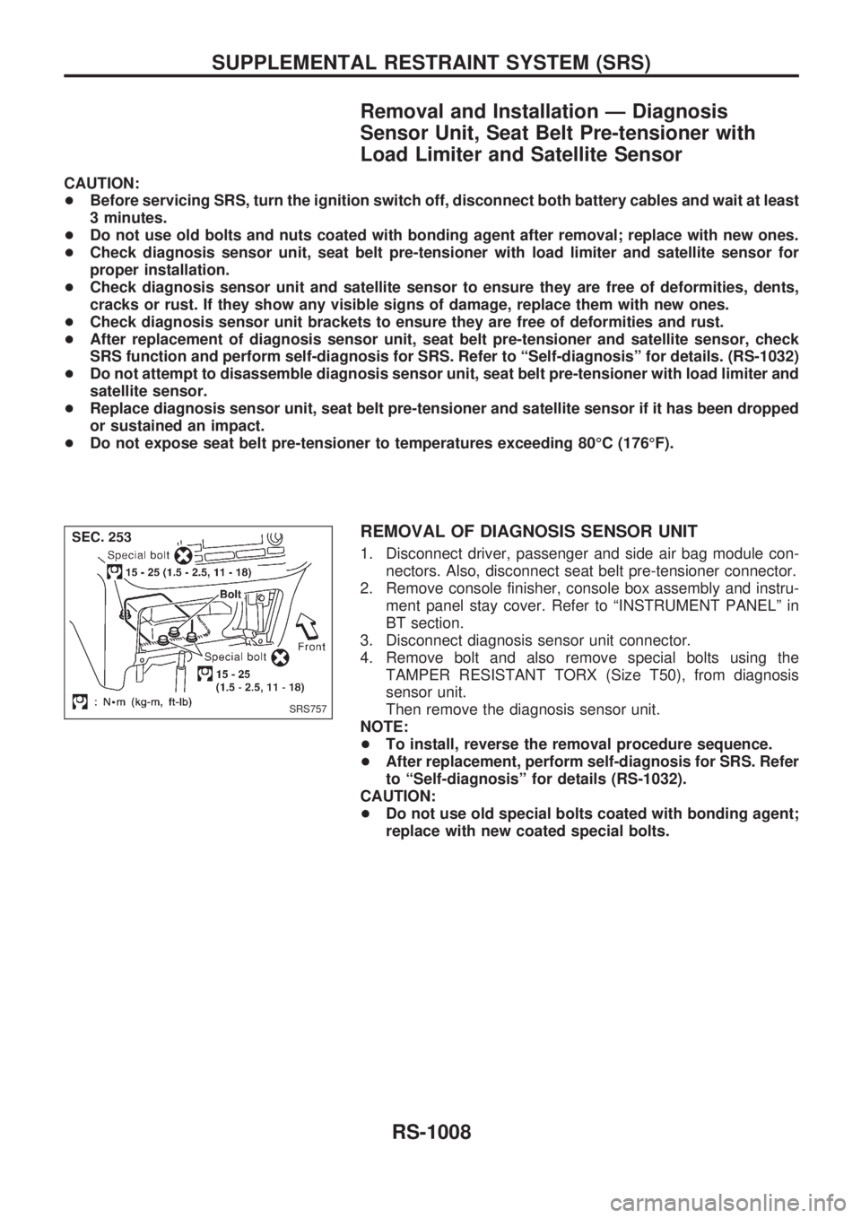
REMOVAL OF DIAGNOSIS SENSOR UNIT
1. Disconnect driver, passenger and side air bag module con-
nectors. Also, disconnect seat belt pre-tensioner connector.
2. Remove console finisher, console box assembly and instru-
ment panel stay cover. Refer to ªINSTRUMENT PANELº in
BT section.
3. Disconnect diagnosis sensor unit connector.
4. Remove bolt and also remove special bolts using the
TAMPER RESISTANT TORX (Size T50), from diagnosis
sensor unit.
Then remove the diagnosis sensor unit.
NOTE:
+To install, reverse the removal procedure sequence.
+After replacement, perform self-diagnosis for SRS. Refer
to ªSelf-diagnosisº for details (RS-1032).
CAUTION:
+Do not use old special bolts coated with bonding agent;
replace with new coated special bolts.
SRS757
SUPPLEMENTAL RESTRAINT SYSTEM (SRS)
RS-1008
Page 981 of 1033
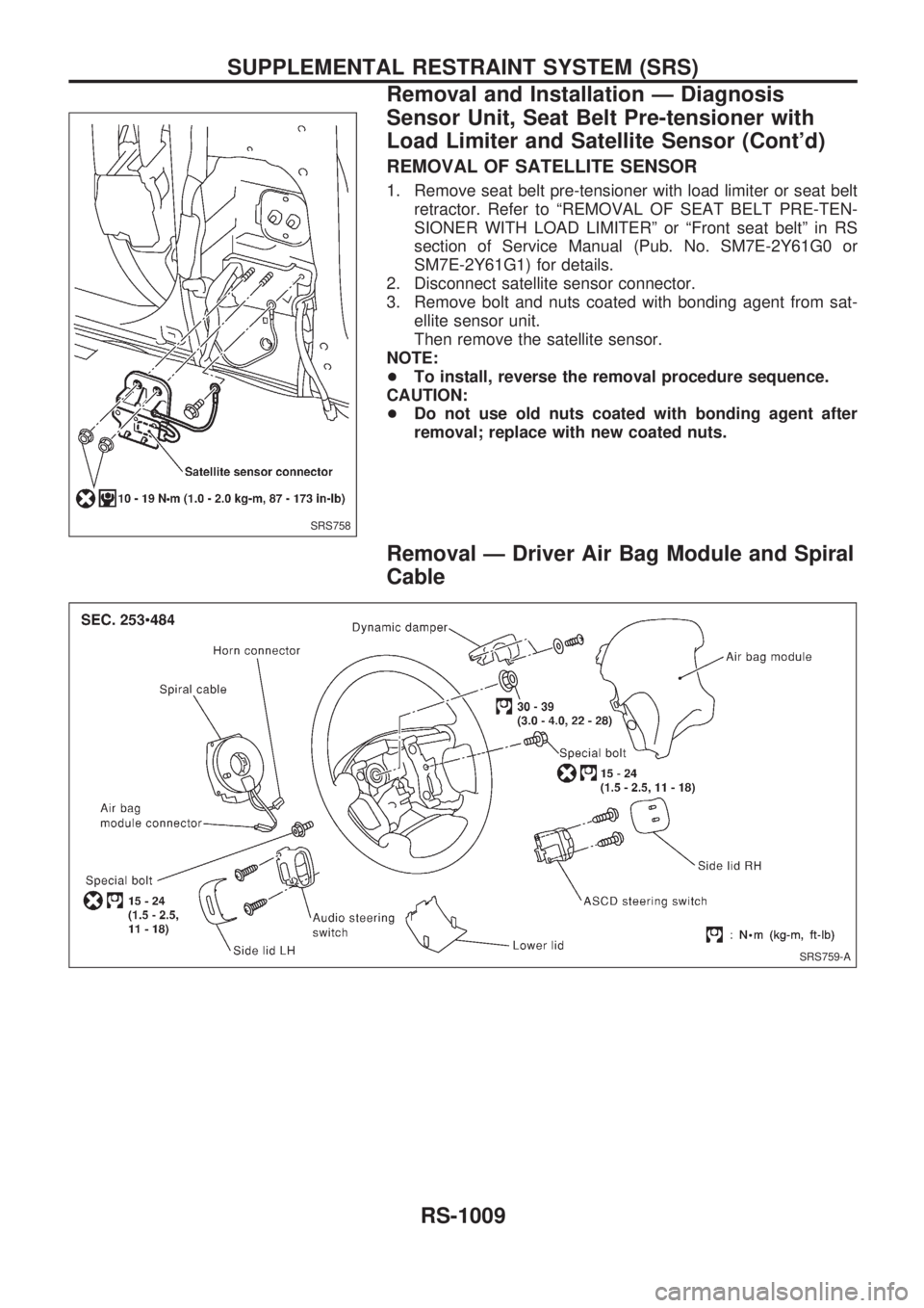
REMOVAL OF SATELLITE SENSOR
1. Remove seat belt pre-tensioner with load limiter or seat belt
retractor. Refer to ªREMOVAL OF SEAT BELT PRE-TEN-
SIONER WITH LOAD LIMITERº or ªFront seat beltº in RS
section of Service Manual (Pub. No. SM7E-2Y61G0 or
SM7E-2Y61G1) for details.
2. Disconnect satellite sensor connector.
3. Remove bolt and nuts coated with bonding agent from sat-
ellite sensor unit.
Then remove the satellite sensor.
NOTE:
+To install, reverse the removal procedure sequence.
CAUTION:
+Do not use old nuts coated with bonding agent after
removal; replace with new coated nuts.
Removal Ð Driver Air Bag Module and Spiral
Cable
SRS758
SRS759-A
SUPPLEMENTAL RESTRAINT SYSTEM (SRS)
Removal and Installation Ð Diagnosis
Sensor Unit, Seat Belt Pre-tensioner with
Load Limiter and Satellite Sensor (Cont'd)
RS-1009
Page 987 of 1033
Disposal of Air Bag Module and Seat Belt
Pre-tensioner
+Before disposing of air bag module and seat belt pre-tensioner, or vehicles equipped with such systems,
deploy the systems. If such systems have already been deployed due to an accident, dispose of them
as indicated in ªDISPOSING OF AIR BAG MODULE AND SEAT BELT PRE-TENSIONERº (RS-1018).
+When deploying the air bag module and seat belt pre-tensioner, always use the Special Service Tool;
Deployment tool KV99106400.
+When deploying the air bag module and seat belt pre-tensioner, stand at least 5 m (16 ft) away from the
deployment component.
+When deploying air bag module and seat belt pre-tensioner, a fairly loud noise is made, followed by
smoke being released. The smoke is not poisonous, however, be careful not to inhale smoke since it
irritates the throat and can cause choking.
+Always activate one air bag module at a time.
+Due to heat, leave air bag module unattended for more than 30 minutes after deployment. Also leave
seat belt pre-tensioner unattended for move than 10 minutes after deployment.
+Be sure to wear gloves when handling a deployed air bag module and seat belt pre-tensioner.
+Never apply water to the deployed air bag module and seat belt pre-tensioner.
+Wash your hands clean after finishing work.
+Place the vehicle outdoors with an open space of at least 6 m (20 ft) on all sides when deploying air
bag module and seat belt pre-tensioner while mounted in vehicle.
+Use a voltmeter to make sure the vehicle battery is fully charged.
+Do not dispose of the air bag module and seat belt pre-tensioner un-deployed.
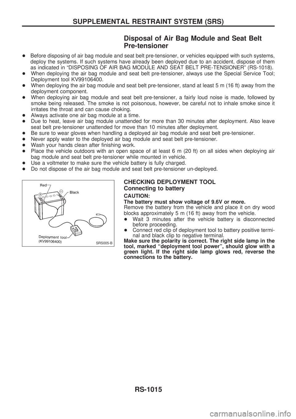
CHECKING DEPLOYMENT TOOL
Connecting to battery
CAUTION:
The battery must show voltage of 9.6V or more.
Remove the battery from the vehicle and place it on dry wood
blocks approximately 5 m (16 ft) away from the vehicle.
+Wait 3 minutes after the vehicle battery is disconnected
before proceeding.
+Connect red clip of deployment tool to battery positive termi-
nal and black clip to negative terminal.
Make sure the polarity is correct. The right side lamp in the
tool, marked ªdeployment tool powerº, should glow with a
green light. If the right side lamp glows red, reverse the
connections to the battery.
SRS005-B
SUPPLEMENTAL RESTRAINT SYSTEM (SRS)
RS-1015
Page 988 of 1033
Deployment tool check
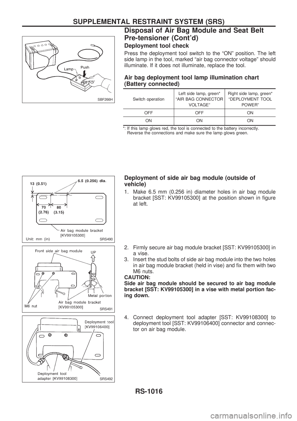
Press the deployment tool switch to the ªONº position. The left
side lamp in the tool, marked ªair bag connector voltageº should
illuminate. If it does not illuminate, replace the tool.
Air bag deployment tool lamp illumination chart
(Battery connected)
Switch operationLeft side lamp, green*
ªAIR BAG CONNECTOR
VOLTAGEºRight side lamp, green*
ªDEPLOYMENT TOOL
POWERº
OFF OFF ON
ON ON ON
*: If this lamp glows red, the tool is connected to the battery incorrectly.
Reverse the connections and make sure the lamp glows green.
Deployment of side air bag module (outside of
vehicle)
1. Make 6.5 mm (0.256 in) diameter holes in air bag module
bracket [SST: KV99105300] at the position shown in figure
at left.
2. Firmly secure air bag module bracket [SST: KV99105300] in
a vise.
3. Insert the stud bolts of side air bag module into the two holes
in air bag module bracket (held in vise) and fix them with two
M6 nuts.
CAUTION:
Side air bag module should be secured to air bag module
bracket [SST: KV99105300] in a vise with metal portion fac-
ing down.
4. Connect deployment tool adapter [SST: KV99108300] to
deployment tool [SST: KV99106400] connector and connec-
tor on air bag module.
SBF266H
SRS490
SRS491
SRS492
SUPPLEMENTAL RESTRAINT SYSTEM (SRS)
Disposal of Air Bag Module and Seat Belt
Pre-tensioner (Cont'd)
RS-1016