2000 NISSAN PATROL belt
[x] Cancel search: beltPage 847 of 1033
Supplemental Restraint System (SRS) ªAIR
BAGº and ªSEAT BELT PRE-TENSIONERº
The Supplemental Restraint System such as ªAIR BAGº and ªSEAT BELT PRE-TENSIONERº used along
with a seat belt, helps to reduce the risk or severity of injury to the driver and front passenger for certain
types of collision. The SRS system composition which is available to NISSAN MODEL Y61 is as follows (The
composition varies according to the destination and optional equipment.):
+For a frontal collision
The Supplemental Restraint System consists of driver air bag module (located in the center of the
steering wheel), front passenger air bag module (located on the instrument panel on passenger side),
seat belt pre-tensioners, a diagnosis sensor unit, warning lamp, wiring harness and spiral cable.
+For a side collision
The Supplemental Restraint System consists of front side air bag module (located in the outer side of
front seat), satellite sensor, diagnosis sensor unit (one of components of air bags for a frontal collision),
wiring harness, warning lamp (one of components of air bags for a frontal collision).
Information necessary to service the system safely is included in theRS sectionof this Service Manual.
WARNING:
+To avoid rendering the SRS inoperative, which could increase the risk of personal injury or death
in the event of a collision which would result in air bag inflation, all maintenance should be per-
formed by an authorized NISSAN dealer.
+Improper maintenance, including incorrect removal and installation of the SRS, can lead to per-
sonal injury caused by unintentional activation of the system. For removal of Spiral Cable and
Air Bag Module, see the RS section.
+Do not use electrical test equipment on any circuit related to the SRS unless instructed to in this
Service Manual. Spiral cable and wiring harnesses covered with yellow insulation tape either just
before the harness connectors or for the complete harness are related to the SRS.
Precautions for Fuel
DIESEL ENGINE*:
Diesel fuel of at least 50 cetane for ZD30DDTi engine
* If two types of diesel fuel are available, use summer or win-
ter fuel properly according to the following temperature con-
ditions.
+Above þ7ÉC (20ÉF) ... Summer type diesel fuel.
+Below þ7ÉC (20ÉF) ... Winter type diesel fuel.
CAUTION:
+Do not use home heating oil, gasoline, or other alternate
fuels in your diesel engine. The use of those can cause
engine damage.
+Do not use summer fuel at temperature below þ7ÉC
(20ÉF). The cold temperature will cause wax to form in
the fuel. As a result, it may prevent the engine from run-
ning smoothly.
+Do not add gasoline or other alternate fuels to diesel
fuel.
PRECAUTIONS AND PREPARATION
GI-1002
Page 856 of 1033
HEATER &
AIR CONDITIONER
SECTION
HA
MODIFICATION NOTICE:
+Wiring diagrams have been changed.
+Cooler cycle for ZD30DDTi engine has been added.
CONTENTS
PRECAUTIONS AND PREPARATION............... 1002
Supplemental Restraint System (SRS) ªAIR
BAGº and ªSEAT BELT PRE-TENSIONERº ... 1002
Precautions for Refrigerant Connection .......... 1002
MANUAL
TROUBLE DIAGNOSES..................................... 1005
Wiring Diagram Ð HEATER Ð ....................... 1005
Wiring Diagram Ð R/HEAT Ð/LHD Models ... 1006
Wiring Diagram Ð A/C, M Ð/ZD Engine ........ 1007
AUTO
TROUBLE DIAGNOSES..................................... 1009
Circuit Diagram ................................................ 1009
Wiring Diagram Ð A/C, A Ð/ZD Engine......... 1010REAR COOLER
TROUBLE DIAGNOSES..................................... 1013
Wiring Diagram Ð R/COOL Ð/LHD Models
with Front Auto A/C ......................................... 1013
Wiring Diagram Ð R/COOL Ð/LHD Models
with Front Manual A/C ..................................... 1015
Wiring Diagram Ð R/COOL Ð/RHD Models
with Front Auto A/C ......................................... 1017
Wiring Diagram Ð R/COOL Ð/RHD Models
with Front Manual A/C ..................................... 1019
MANUAL AND AUTO
SERVICE PROCEDURES................................... 1021
Refrigerant Lines.............................................. 1021
Compressor Mounting...................................... 1023
HA
Page 857 of 1033
Supplemental Restraint System (SRS) ªAIR
BAGº and ªSEAT BELT PRE-TENSIONERº
The Supplemental Restraint System such as ªAIR BAGº and ªSEAT BELT PRE-TENSIONERº used along
with a seat belt, helps to reduce the risk or severity of injury to the driver and front passenger for certain
types of collision. The SRS system composition which is available to NISSAN MODEL Y61 is as follows (The
composition varies according to the destination and optional equipment.):
+For a frontal collision
The Supplemental Restraint System consists of driver air bag module (located in the center of the
steering wheel), front passenger air bag module (located on the instrument panel on passenger side),
seat belt pre-tensioners, a diagnosis sensor unit, warning lamp, wiring harness and spiral cable.
+For a side collision
The Supplemental Restraint System consists of front side air bag module (located in the outer side of
front seat), satellite sensor, diagnosis sensor unit (one of components of air bags for a frontal collision),
wiring harness, warning lamp (one of components of air bags for a frontal collision).
Information necessary to service the system safely is included in theRS sectionof this Service Manual.
WARNING:
+To avoid rendering the SRS inoperative, which could increase the risk of personal injury or death
in the event of a collision which would result in air bag inflation, all maintenance should be per-
formed by an authorized NISSAN dealer.
+Improper maintenance, including incorrect removal and installation of the SRS, can lead to per-
sonal injury caused by unintentional activation of the system. For removal of Spiral Cable and
Air Bag Module, see the RS section.
+Do not use electrical test equipment on any circuit related to the SRS unless instructed to in this
Service Manual. Spiral cable and wiring harnesses covered with yellow insulation tape either just
before the harness connectors or for the complete harness are related to the SRS.
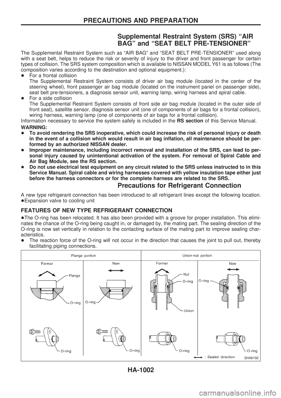
Precautions for Refrigerant Connection
A new type refrigerant connection has been introduced to all refrigerant lines except the following location.
+Expansion valve to cooling unit
FEATURES OF NEW TYPE REFRIGERANT CONNECTION
+The O-ring has been relocated. It has also been provided with a groove for proper installation. This elimi-
nates the chance of the O-ring being caught in, or damaged by, the mating part. The sealing direction of the
O-ring is now set vertically in relation to the contacting surface of the mating part to improve sealing char-
acteristics.
+The reaction force of the O-ring will not occur in the direction that causes the joint to pull out, thereby
facilitating piping connections.
SHA815E
PRECAUTIONS AND PREPARATION
HA-1002
Page 880 of 1033
A
A/T - Wiring diagram ............................. AT-1009
A/T control ............................................. EC-1148
A/T fluid temperature sensor ................. AT-1081
A/T mode switch .................................... AT-1095
A/T self-diagnoses ................................. AT-1028
A/T shift lock system - Wiring
diagram .............................................. AT-1117
A/T shift lock system ............................. AT-1116
A/T trouble diagnoses ........................... AT-1036
APS - Wiring diagram ........................... EC-1125
ASCD (automatic speed control
device) ............................................... EL-1110
ASCD - Wiring diagram ......................... EL-1111
AT/C - Wiring diagram .......................... EC-1150
Accelerator control system .................... FE-1007
Accelerator position sensor .................. EC-1125
Air bag disposal .................................... RS-1015
Air bag precautions ................................ GI-1002
Air bag ................................................... RS-1003
Air cleaner filter replacement ............... MA-1019
Air conditioner cut control ..................... EC-1021
Air flow meter - See Mass air flow
sensor ................................................ EC-1086
Alternator ............................................... EL-1041
Angular tightening application .............. EM-1003
Anti-lock brake system - Wiring
diagram ............................................. BR-1002
Audio ...................................................... EL-1108
Automatic speed control system - See
ASCD ................................................. EL-1110
Automatic transmission fluid
replacement ...................................... MA-1021
B
BACK/L - Wiring diagram ...................... EL-1051
BOOST - Wiring diagram ...................... EC-1204
Back-up lamp ......................................... EL-1051
Basic inspection .................................... EC-1049
Battery ................................................... EL-1035
Boring/horning cylinder block ............... EM-1075
C
CHARGE - Wiring diagram ................... EL-1040
CKPS - Wiring diagram ........................ EC-1140
CONSULT for engine ............................ EC-1038
CONSULT general information .............. GI-1003
COOL/F - Wiring diagram ..................... EC-1105
CORNER - Wiring diagram ................... EL-1054
Camshaft inspection ............................. EM-1032
Charging system .................................... EL-1040
Chassis and body maintenance ........... MA-1020
Clutch operating cylinder ....................... CL-1003
Collision diagnosis ................................ RS-1052
Combination meter ................................ EL-1073Combination switch ............................... EL-1042
Compression pressure ......................... EM-1010
Compressor mounting ........................... HA-1023
Connecting rod bearing clearance ....... EM-1078
Connecting rod bushing clearance ....... EM-1074
Connecting rod ..................................... EM-1074
Control valve (A/T) ................................ AT-1148
Converter housing installation ............... AT-1128
Coolant mixture ratio ............................ MA-1010
Coolant replacement ............................ MA-1014
Cooling fan control ................................ EC-1105
Cornering lamp ...................................... EL-1054
Crankcase emission control system -
See Positive crankcase ventilation ... EC-1022
Crankcase ventilation system - See
Positive crankcase ventilation ........... EC-1022
Crankshaft position sensor (TDC) ........ EC-1140
Crankshaft ............................................ EM-1077
Cruise control - See ASCD ................... EL-1110
Cylinder block boring ............................ EM-1020
Cylinder block ....................................... EM-1067
Cylinder head bolt tightening ................ EM-1034
Cylinder head ....................................... EM-1053
D
DEF - Wiring diagram ............................ EL-1102
DTRL - Wiring diagram ......................... EL-1044
Data link connector for Consult ............ EC-1038
Daytime light system ............................. EL-1044
Diagnosis sensor unit ........................... RS-1008
Diagnostic trouble code (DTC) for
OBD system ...................................... EC-1032
Dome light - See Interior lamp .............. EL-1067
Door mirror ............................................ BT-1007
Door trim ................................................ BT-1004
Drive belt inspection ............................. MA-1011
Drive plate runout ................................. EM-1095
Dropping resistor (A/T) .......................... AT-1086
E
ECCS-D control module .. EC-1068, 1117, 1189,
1191, 1196, 1200
ECM input/output signal ........................ EC-1068
ECTS - Wiring diagram ......................... EC-1092
EGR - Wiring diagram .......................... EC-1209
EGR volume control valve .................... EC-1207
Electrical unit ......................................... EL-1231
Electrical units location .......................... EL-1185
Electronic fuel injection pump .... EC-1119, 1153,
1159, 1165, 1171, 1177, 1180, 1215
Engine control circuit diagram .............. EC-1015
Engine control component parts
location .............................................. EC-1011
Engine control system diagram and
chart .................................................. EC-1016
ALPHABETICAL INDEX
IDX-1002
Page 882 of 1033
O
Oil change (capacity) ............................ MA-1008
Oil pan (engine) .................................... EM-1022
Oil pump (A/T) ....................................... AT-1144
Oil seal replacement (engine) .............. EM-1051
On board diagnostic system ................. EC-1032
Operating cylinder (clutch) .................... CL-1003
Outside mirror ........................................ BT-1007
Overdrive control switch ........................ AT-1095
Overrun clutch solenoid valve ............... AT-1075
Overrun clutch ....................................... AT-1167
Oversize piston ..................................... EM-1075
P
P/ANT - Wiring diagram ........................ EL-1109
PCV (positive crankcase ventilation) .... EC-1022
PNP/SW - Wiring diagram .................... EC-1233
POWER - Wiring diagram ..................... EL-1005
Park/Neutral position switch ................. EC-1233
Park/neutral position switch (A/T) ......... AT-1095
Parking lamp .......................................... EL-1046
Pilot bushing replacement - See Pilot
converter ........................................... EM-1083
Piston pin inspection ............................ EM-1072
Piston ring inspection ........................... EM-1073
Piston to bore clearance ...................... EM-1076
Power antenna ...................................... EL-1109
Power supply routing ............................. EL-1004
Power window ....................................... EL-1115
Pressure test (A/T) ................................ AT-1044
Priming pump ........................................ EC-1049
Propeller shaft on vehicle service ......... PD-1003
Propeller shaft vibration ........................ PD-1003
Propeller shaft ....................................... PD-1002
Q
Quick-glow system ................................ EC-1221
R
R/COOL - Wiring diagram
(front auto A/C) ....................... HA-1013, 1017
R/COOL - Wiring diagram (front
manual A/C) ...................................... HA-1019
R/HEAT - Wiring diagram ..................... HA-1006
ROOM/L - Wiring diagram ..................... EL-1068
Radio - See Audio ................................. EL-1108
Rear cooler - Wiring diagram (front
auto A/C) ................................. HA-1013, 1017
Rear cooler - Wiring diagram (front
manual A/C) ...................................... HA-1019
Rear fog lamp ........................................ EL-1053
Rear heater - Wiring diagram ............... HA-1006Rear window defogger .......................... EL-1101
Refrigerant lines .................................... HA-1021
Removal and installation (A/T) .............. AT-1127
Reverse clutch ....................................... AT-1161
Revolution sensor (A/T) ........................ AT-1065
Room lamp - See Interior lamp ............. EL-1067
S
S/LOCK - Wiring diagram ...................... EL-1128
S/TANK - Wiring diagram ...................... FE-1003
SHIFT - Wiring diagram ........................ AT-1117
SRS - See Supplemental Restraint
System .............................................. RS-1003
STAB - Wiring diagram ......................... RA-1002
START - Wiring diagram ....................... EL-1036
SWL/V - Wiring diagram ....................... EC-1248
Screw jack .............................................. GI-1009
Seat belt pre-tensioner disposal ........... RS-1015
Seat belt pre-tensioner ......................... RS-1003
Seat, front .............................................. BT-1006
Self-diagnostic results ........................... EC-1034
Shift lock system ................................... AT-1116
Shift schedule ........................................ AT-1206
Shift solenoid valve A (A/T) .................. AT-1071
Shift solenoid valve B (A/T) .................. AT-1073
Side air bag ........................................... RS-1003
Speedometer ......................................... EL-1073
Spiral cable ........................................... RS-1009
Stabilizer release device - Wiring
diagram ............................................. RA-1002
Stabilizer release device ....................... RA-1002
Stall test (A/T) ....................................... AT-1041
Start signal ............................................ EC-1230
Starter .................................................... EL-1039
Starting system ...................................... EL-1036
Steering switch ...................................... EL-1043
Stop lamp .............................................. EL-1050
Super lock ................................... EL-1124, 1159
Supplemental Restraint System ........... RS-1003
Supplemental restraint system - Wiring
diagram ................................... RS-1024, 1028
Swirl control valve control solenoid
valve .................................................. EC-1246
Symptom matrix chart ........................... EC-1055
T
TCM circuit diagram .............................. AT-1008
TCM inspection table ............................ AT-1060
Tachometer ............................................ EL-1073
Tail lamp ................................................ EL-1046
Throttle position switch .......................... AT-1096
Timing chain ......................................... EM-1027
Timing gear ........................................... EM-1039
Torque converter clutch solenoid
valve .................................................. AT-1078
Torque converter installation ................. AT-1128
ALPHABETICAL INDEX
IDX-1004
Page 890 of 1033
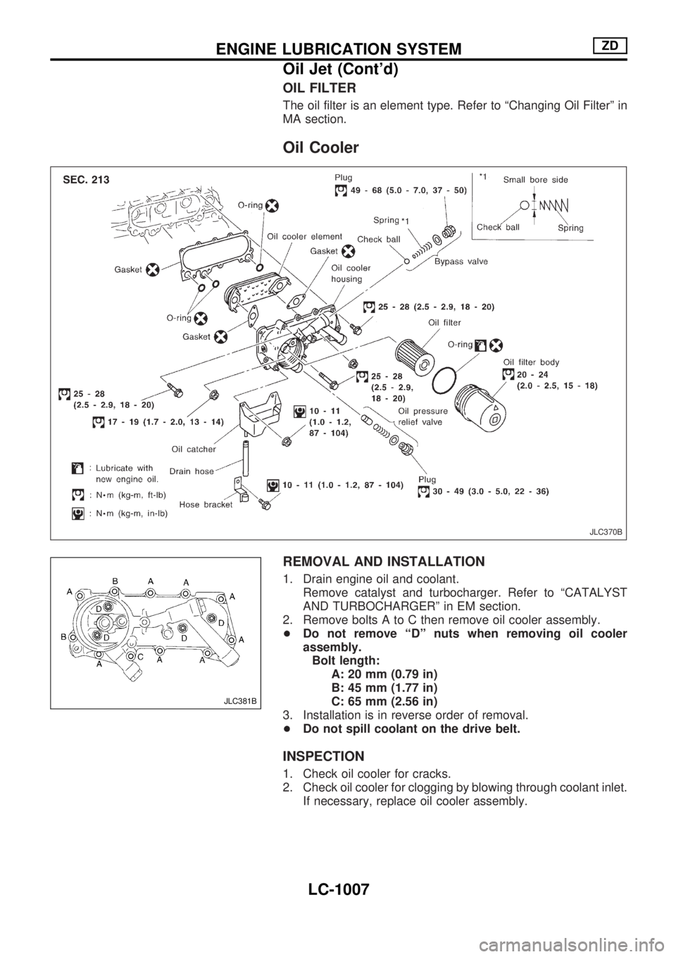
OIL FILTER
The oil filter is an element type. Refer to ªChanging Oil Filterº in
MA section.
Oil Cooler
REMOVAL AND INSTALLATION
1. Drain engine oil and coolant.
Remove catalyst and turbocharger. Refer to ªCATALYST
AND TURBOCHARGERº in EM section.
2. Remove bolts A to C then remove oil cooler assembly.
+Do not remove ªDº nuts when removing oil cooler
assembly.
Bolt length:
A: 20 mm (0.79 in)
B: 45 mm (1.77 in)
C: 65 mm (2.56 in)
3. Installation is in reverse order of removal.
+Do not spill coolant on the drive belt.
INSPECTION
1. Check oil cooler for cracks.
2. Check oil cooler for clogging by blowing through coolant inlet.
If necessary, replace oil cooler assembly.
JLC370B
JLC381B
ENGINE LUBRICATION SYSTEMZD
Oil Jet (Cont'd)
LC-1007
Page 893 of 1033
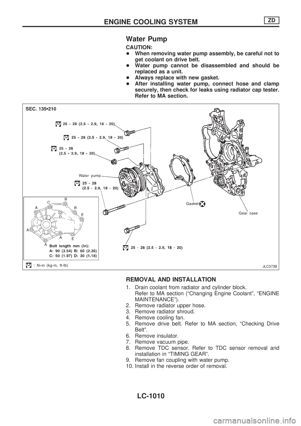
Water Pump
CAUTION:
+When removing water pump assembly, be careful not to
get coolant on drive belt.
+Water pump cannot be disassembled and should be
replaced as a unit.
+Always replace with new gasket.
+After installing water pump, connect hose and clamp
securely, then check for leaks using radiator cap tester.
Refer to MA section.
REMOVAL AND INSTALLATION
1. Drain coolant from radiator and cylinder block.
Refer to MA section (ªChanging Engine Coolantº, ªENGINE
MAINTENANCEº).
2. Remove radiator upper hose.
3. Remove radiator shroud.
4. Remove cooling fan.
5. Remove drive belt. Refer to MA section, ªChecking Drive
Beltº.
6. Remove insulator.
7. Remove vacuum pipe.
8. Remove TDC sensor. Refer to TDC sensor removal and
installation in ªTIMING GEARº.
9. Remove fan coupling with water pump.
10. Install in the reverse order of removal.
JLC373B
ENGINE COOLING SYSTEMZD
LC-1010
Page 897 of 1033
11. Remove radiator.
12. After repairing or replacing radiator, install all removed parts
in reverse order of removal.
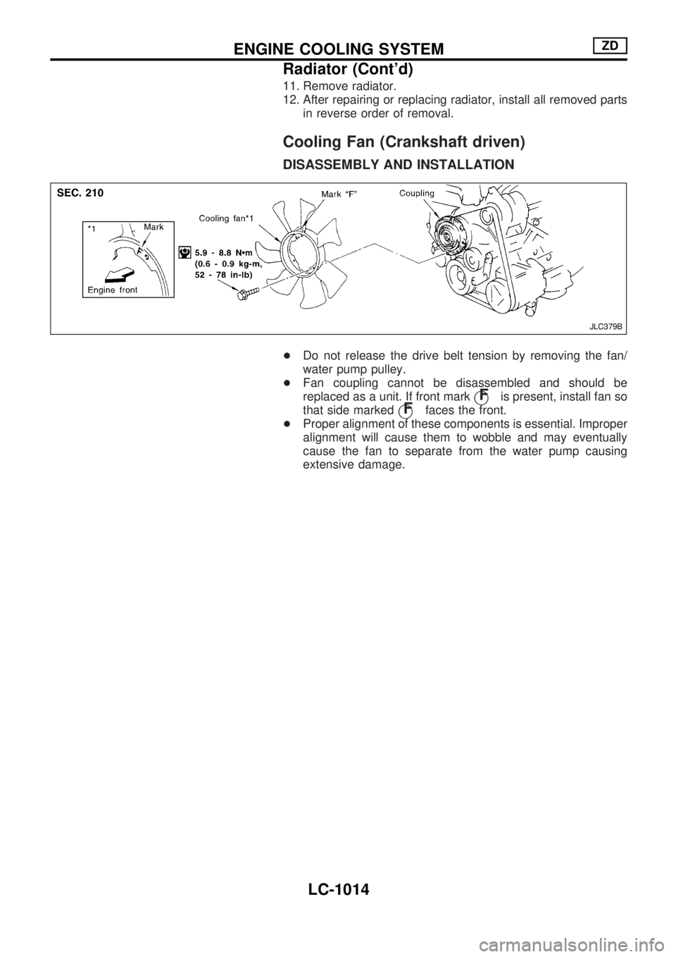
Cooling Fan (Crankshaft driven)
DISASSEMBLY AND INSTALLATION
+Do not release the drive belt tension by removing the fan/
water pump pulley.
+Fan coupling cannot be disassembled and should be
replaced as a unit. If front mark
jFis present, install fan so
that side marked
jFfaces the front.
+Proper alignment of these components is essential. Improper
alignment will cause them to wobble and may eventually
cause the fan to separate from the water pump causing
extensive damage.
JLC379B
ENGINE COOLING SYSTEMZD
Radiator (Cont'd)
LC-1014