2000 NISSAN PATROL belt
[x] Cancel search: beltPage 899 of 1033
MAINTENANCE
SECTION
MA
MODIFICATION NOTICE:
+ The ZD30DDTi engine has been replaced with the RD28ETi engine.
+ Descriptions for the engine coolant mixture ratio have been modified.
CONTENTS
PERIODIC MAINTENANCE ................................ 1002
Maintenance Schedule for Diesel Engines
(Annual Mileage < 30,000 km/year) ................ 1002
Chassis and Body Maintenance ...................... 1003
Maintenance Under Severe Driving Conditions
(Annual Driving Distance < 30,000 km/year)... 1004
Maintenance Schedule for Diesel Engines
(Annual Mileage > 30,000 km/year) ................ 1005
Chassis and Body Maintenance ...................... 1006
Maintenance Under Severe Driving Conditions
(AnnualDrivingDistance>30,000km/year)...1007
RECOMMENDED FLUIDS AND
LUBRICANTS ...................................................... 1008
Fluids and Lubricants....................................... 1008
SAE Viscosity Number..................................... 1009
Engine Coolant Mixture Ratio .......................... 1010
ZD
ENGINE MAINTENANCE .................................... 1011
Checking Tightening Torque............................ 1011 Adjusting Intake and Exhaust Valve
Clearance ......................................................... 1011
Checking Drive Belt ......................................... 1011
Removal ........................................................... 1012
Installation ........................................................ 1012
Changing Engine Oil ........................................ 1012
Changing Engine Oil Filter............................... 1013
Changing Engine Coolant ................................ 1014
Checking Cooling System................................ 1016
Checking and Replacing Fuel Filter and
Draining Water ................................................. 1017
Checking Fuel Lines ........................................ 1018
Cleaning and Replacing Air Cleaner Filter ...... 1019
CHASSIS AND BODY MAINTENANCE ............. 1020
Checking A/T Fluid .......................................... 1020
Changing A/T Fluid .......................................... 1021
SERVICE DATA AND SPECIFICATIONS
(SDS) .................................................................... 1022
Engine Maintenance (ZD) ................................ 1022
MA
Page 900 of 1033
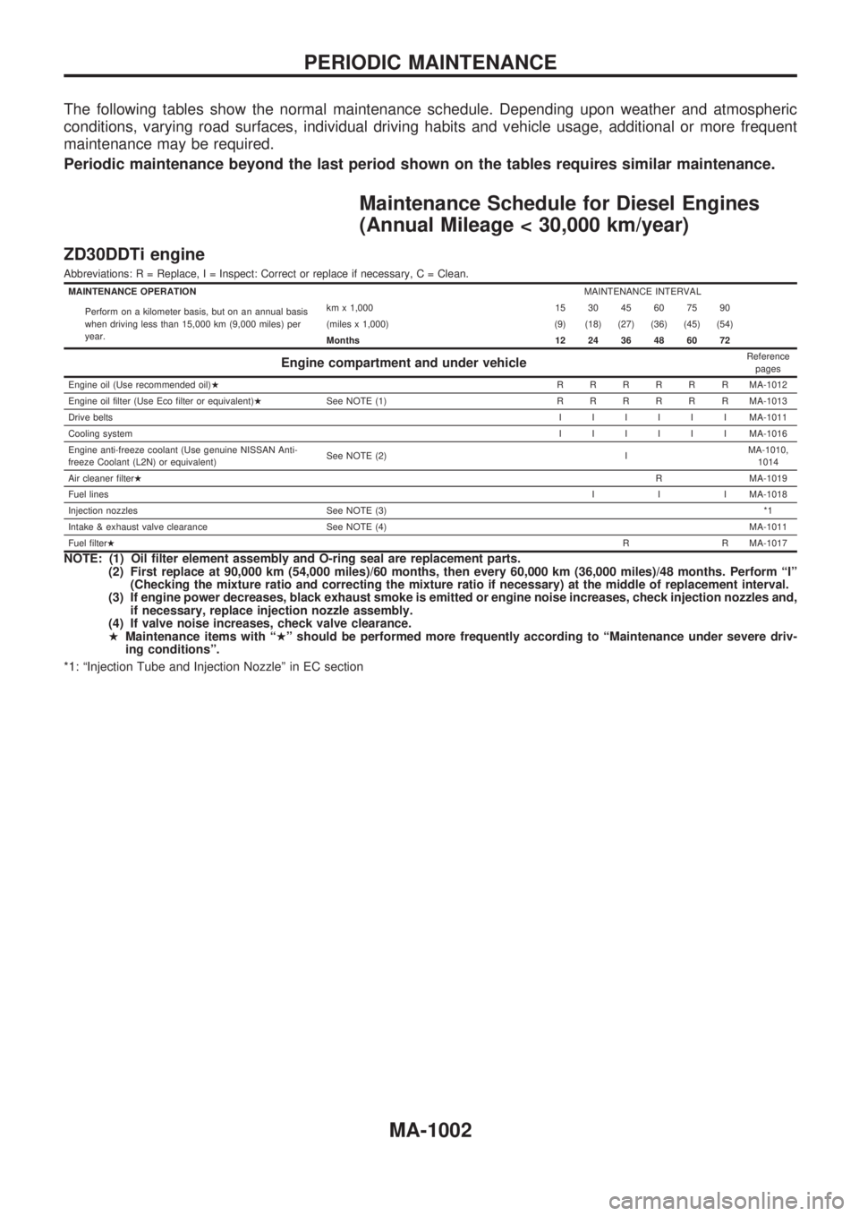
The following tables show the normal maintenance schedule. Depending upon weather and atmospheric
conditions, varying road surfaces, individual driving habits and vehicle usage, additional or more frequent
maintenance may be required.
Periodic maintenance beyond the last period shown on the tables requires similar maintenance.
Maintenance Schedule for Diesel Engines
(Annual Mileage < 30,000 km/year)
ZD30DDTi engine
Abbreviations: R = Replace, I = Inspect: Correct or replace if necessary, C = Clean.
MAINTENANCE OPERATIONMAINTENANCE INTERVAL
Perform on a kilometer basis, but on an annual basis
when driving less than 15,000 km (9,000 miles) per
year.km x 1,000 15 30 45 60 75 90
(miles x 1,000) (9) (18) (27) (36) (45) (54)
Months 12 24 36 48 60 72
Engine compartment and under vehicleReference
pages
Engine oil (Use recommended oil)HRRRRRRMA-1012
Engine oil filter (Use Eco filter or equivalent)HSee NOTE (1)RRRRRRMA-1013
Drive beltsIIIIIIMA-1011
Cooling systemIIIIIIMA-1016
Engine anti-freeze coolant (Use genuine NISSAN Anti-
freeze Coolant (L2N) or equivalent)See NOTE (2) IMA-1010,
1014
Air cleaner filterHR MA-1019
Fuel linesI I I MA-1018
Injection nozzles See NOTE (3)*1
Intake & exhaust valve clearance See NOTE (4)MA-1011
Fuel filterHR R MA-1017
NOTE: (1) Oil filter element assembly and O-ring seal are replacement parts.
(2) First replace at 90,000 km (54,000 miles)/60 months, then every 60,000 km (36,000 miles)/48 months. Perform ªIº
(Checking the mixture ratio and correcting the mixture ratio if necessary) at the middle of replacement interval.
(3) If engine power decreases, black exhaust smoke is emitted or engine noise increases, check injection nozzles and,
if necessary, replace injection nozzle assembly.
(4) If valve noise increases, check valve clearance.
HMaintenance items with ªHº should be performed more frequently according to ªMaintenance under severe driv-
ing conditionsº.
*1: ªInjection Tube and Injection Nozzleº in EC section
PERIODIC MAINTENANCE
MA-1002
Page 903 of 1033
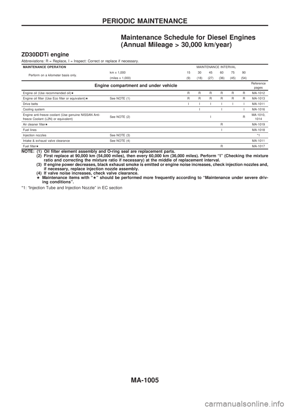
Maintenance Schedule for Diesel Engines
(Annual Mileage > 30,000 km/year)
ZD30DDTi engine
Abbreviations: R = Replace, I = Inspect: Correct or replace if necessary.
MAINTENANCE OPERATIONMAINTENANCE INTERVAL
Perform on a kilometer basis only.km x 1,000 15 30 45 60 75 90
(miles x 1,000) (9) (18) (27) (36) (45) (54)
Engine compartment and under vehicleReference
pages
Engine oil (Use recommended oil)HRRRRRRMA-1012
Engine oil filter (Use Eco filter or equivalent)HSee NOTE (1)RRRRRRMA-1013
Drive beltsIIIIIIMA-1011
Cooling systemI I I MA-1016
Engine anti-freeze coolant (Use genuine NISSAN Anti-
freeze Coolant (L2N) or equivalent)See NOTE (2) I RMA-1010,
1014
Air cleaner filterHR MA-1019
Fuel linesI MA-1018
Injection nozzles See NOTE (3)*1
Intake & exhaust valve clearance See NOTE (4)MA-1011
Fuel filterHR MA-1017
NOTE: (1) Oil filter element assembly and O-ring seal are replacement parts.
(2) First replace at 90,000 km (54,000 miles), then every 60,000 km (36,000 miles). Perform ªIº (Checking the mixture
ratio and correcting the mixture ratio if necessary) at the middle of replacement interval.
(3) If engine power decreases, black exhaust smoke is emitted or engine noise increases, check injection nozzles and,
if necessary, replace injection nozzle assembly.
(4) If valve noise increases, check valve clearance.
HMaintenance items with ªHº should be performed more frequently according to ªMaintenance under severe driv-
ing conditionsº.
*1: ªInjection Tube and Injection Nozzleº in EC section
PERIODIC MAINTENANCE
MA-1005
Page 909 of 1033
Checking Tightening Torque
Checking should be performed while engine is cold.
MANIFOLD BOLTS AND NUTS
Intake and exhaust manifolds:
Intake
:25-28Nzm (2.5 - 2.9 kg-m, 18 - 20 ft-lb)
Exhaust
:40-49Nzm (4.0 - 4.5 kg-m, 29 - 36 ft-lb)
Adjusting Intake and Exhaust Valve
Clearance
Refer to EM section.
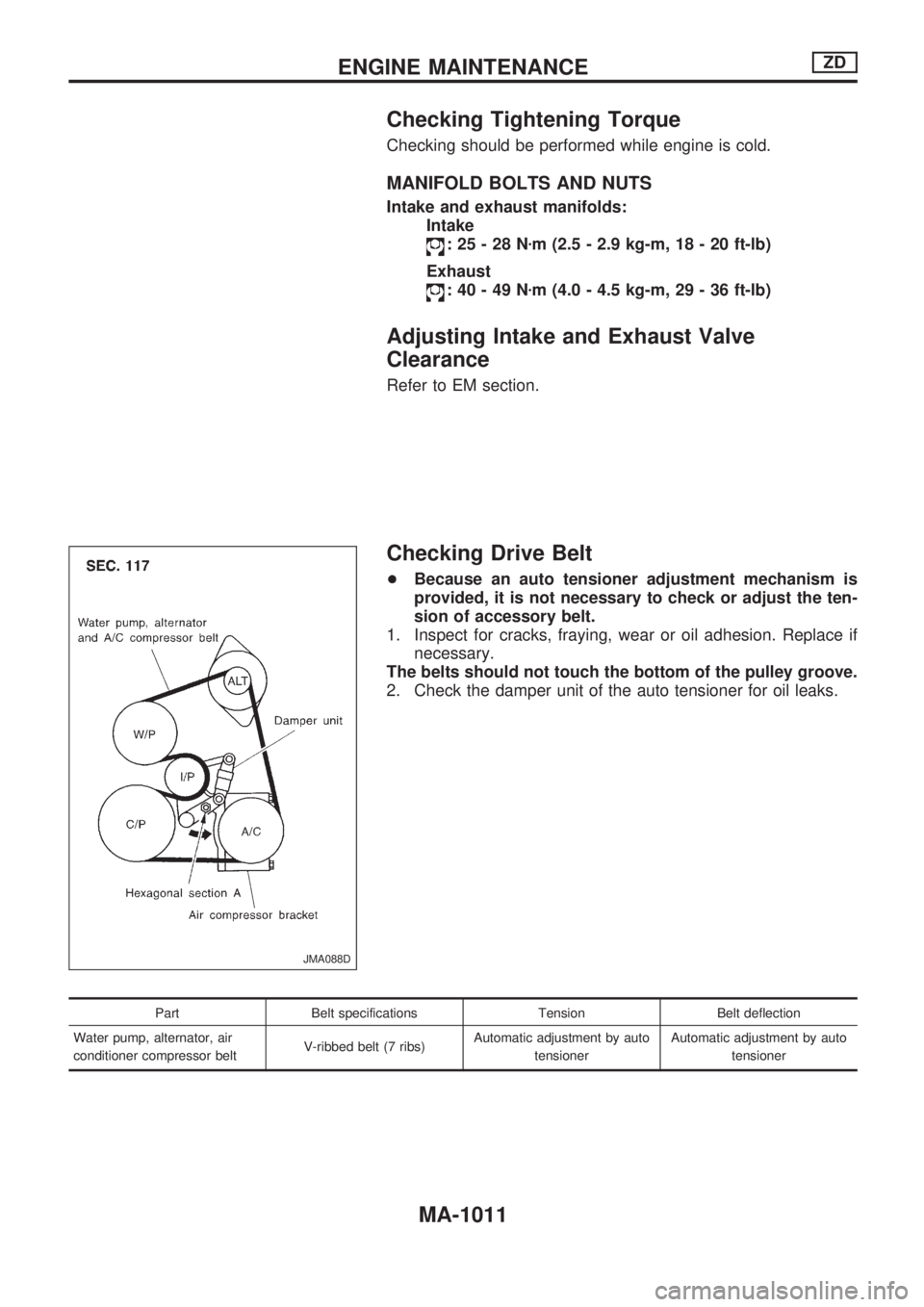
Checking Drive Belt
+Because an auto tensioner adjustment mechanism is
provided, it is not necessary to check or adjust the ten-
sion of accessory belt.
1. Inspect for cracks, fraying, wear or oil adhesion. Replace if
necessary.
The belts should not touch the bottom of the pulley groove.
2. Check the damper unit of the auto tensioner for oil leaks.
Part Belt specifications Tension Belt deflection
Water pump, alternator, air
conditioner compressor beltV-ribbed belt (7 ribs)Automatic adjustment by auto
tensionerAutomatic adjustment by auto
tensioner
JMA088D
ENGINE MAINTENANCEZD
MA-1011
Page 910 of 1033
Removal
WATER PUMP, ALTERNATOR AND AIR
CONDITIONER BELT
1. Remove radiator shroud.
2. Contract and hold the auto tensioner using the following pro-
cedure.
a. Securely hold the 19 mm (0.75 in) hexagonal portion A of
auto tensioner with a closed wrench.
+Preferably use a tool with a handhold of 500 mm (19.69 in)
or more in length.
+No bolts or nuts are required to be loosened during the
operation.
b. Turn the hexagonal portion A in the direction shown by the
arrow to contract the damper unit of the auto tensioner.
CAUTION:
+Because the tensioner has a high tension, it shall be
securely held and turned with a closed wrench.
+Because the hexagonal portion A of the tensioner is
made of aluminum and may be damaged by sudden
input, turn it slowly according to the contraction of the
damper unit.
3. Remove the belt from the alternator pulley first, and then
remove it from the other pulleys.
+If the tensioner is not held firmly, your finger may get caught
between the belt and the pulleys. Confirm the holding of the
tensioner, and then hold the belt side in the place away from
the pulleys to attach or remove the belt, paying attention to
prevent your finger from being caught.
CAUTION:
+When handling the belt, pay attention to prevent the oil
or coolant from adhering to the belt.
+Do not distort or bend the belt intensively.
Installation
+Install the belt in the reverse order of removal.
+After installation of the belt, confirm that the belt engages the
pulleys securely.
+Depending on the engagement between the belt and the idler
pulley, noise (belt noise) may be heard when the engine is
started just after installation. This noise will stop with time.
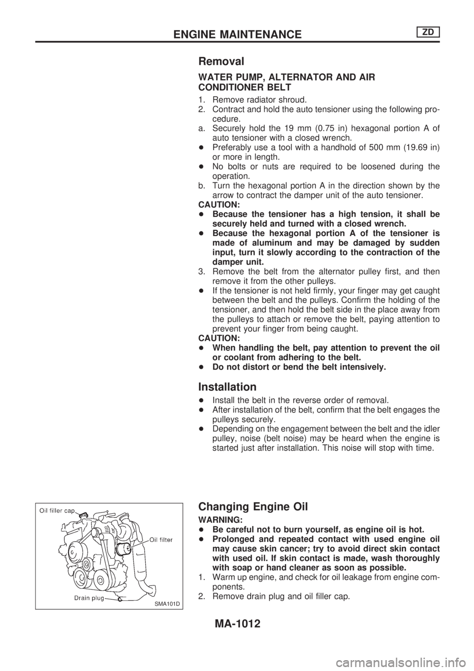
Changing Engine Oil
WARNING:
+Be careful not to burn yourself, as engine oil is hot.
+Prolonged and repeated contact with used engine oil
may cause skin cancer; try to avoid direct skin contact
with used oil. If skin contact is made, wash thoroughly
with soap or hand cleaner as soon as possible.
1. Warm up engine, and check for oil leakage from engine com-
ponents.
2. Remove drain plug and oil filler cap.
SMA101D
ENGINE MAINTENANCEZD
MA-1012
Page 973 of 1033
RESTRAINT SYSTEM
SECTION
RS
MODIFICATION NOTICE:
+Side air bag has been adopted as optional equipment.
+Diagnosis sensor unit has been changed.
+Seat belt pre-tensioner with load limiter has been added.
+Deployment procedure of seat belt pre-tensioner has been changed.
CONTENTS
PRECAUTION...................................................... 1002
Supplemental Restraint System (SRS) ªAIR
BAGº and ªSEAT BELT PRE-TENSIONERº ... 1002
SUPPLEMENTAL RESTRAINT SYSTEM (SRS)1003
Precautions for SRS ªAIR BAGº and ªSEAT
BELT PRE-TENSIONERº Service ................... 1003
Special Service Tools ...................................... 1003
Description ....................................................... 1004
Built-in Type Side Air Bag ............................... 1004
Seat Belt Pre-tensioner with Load Limiter ....... 1005
SRS Component Parts Location...................... 1005
Maintenance Items........................................... 1006
Removal and Installation Ð Diagnosis Sensor
Unit, Seat Belt Pre-tensioner with Load Limiter
and Satellite Sensor......................................... 1008
Removal Ð Driver Air Bag Module and Spiral
Cable ................................................................ 1009Installation Ð Driver Air Bag Module and
Spiral Cable ..................................................... 1011
Removal Ð Side Air Bag Module.................... 1012
Installation Ð Side Air Bag Module................. 1013
Disposal of Air Bag Module and Seat Belt
Pre-tensioner.................................................... 1015
TROUBLE DIAGNOSES Ð Supplemental
Restraint System (SRS)..................................... 1019
Trouble Diagnoses Introduction ....................... 1019
How to Perform Trouble Diagnoses for Quick
and Accurate Repair ........................................ 1021
Schematic ........................................................ 1023
Wiring Diagram Ð SRS Ð/LHD Models ......... 1024
Wiring Diagram Ð SRS Ð/RHD Models ........ 1028
Self-diagnosis................................................... 1032
Trouble Diagnoses for Air Bag Warning Lamp1050
COLLISION DIAGNOSIS..................................... 1052
RS
Page 974 of 1033
Supplemental Restraint System (SRS) ªAIR
BAGº and ªSEAT BELT PRE-TENSIONERº
The Supplemental Restraint System such as ªAIR BAGº and ªSEAT BELT PRE-TENSIONERº used along
with a seat belt, helps to reduce the risk or severity of injury to the driver and front passenger for certain
types of collision. The SRS composition which is available to NISSAN MODEL Y61 is as follows (The com-
position varies according to the destination and optional equipment.):
+For a frontal collision
The Supplemental Restraint System consists of driver air bag module (located in the center of the
steering wheel), front passenger air bag module (located on the instrument panel on passenger side),
seat belt pre-tensioners, a diagnosis sensor unit, warning lamp, wiring harness and spiral cable.
+For a side collision
The Supplemental Restraint System consists of front side air bag module (located in the outer side of
front seat), satellite sensor, diagnosis sensor unit (one of components of air bags for a frontal collision),
wiring harness, warning lamp (one of components of air bags for a frontal collision).
WARNING:
+To avoid rendering the SRS inoperative, which could increase the risk of personal injury or death
in the event of a collision which would result in air bag inflation, all maintenance should be per-
formed by an authorized NISSAN dealer.
+Improper maintenance, including incorrect removal and installation of the SRS, can lead to per-
sonal injury caused by unintentional activation of the system.
+Do not use electrical test equipment on any circuit related to the SRS unless instructed to in this
Service Manual. Spiral cable and wiring harnesses covered with yellow insulation tape either just
before the harness connectors or for the complete harness are related to the SRS.
PRECAUTION
RS-1002
Page 975 of 1033
Precautions for SRS ªAIR BAGº and ªSEAT
BELT PRE-TENSIONERº Service
+Do not use electrical test equipment to check SRS circuits unless instructed to in this Service Manual.
+Before servicing the SRS, turn ignition switch ªOFFº, disconnect both battery cables and wait at least 3
minutes.
For approximately 3 minutes after the cables are removed, it is still possible for the air bag and seat belt pre-
tensioner to deploy. Therefore, do not work on any SRS connectors or wires until at least 3 minutes have passed.
+Diagnosis sensor unit must always be installed with their arrow marks ªSº pointing towards the front of
the vehicle for proper operation. Also check diagnosis sensor unit for cracks, deformities or rust before
installation and replace as required.
+The spiral cable must be aligned with the neutral position since its rotations are limited. Do not attempt
to turn steering wheel or column after removal of steering gear.
+Handle air bag module carefully. Always place driver and passenger air bag modules with the pad side
facing upward and front side air bag modules (built-in type) with the stud bolt side facing down.
+Conduct self-diagnosis to check entire SRS for proper function after replacing any components.
+After air bag inflates, the front instrument panel assembly should be replaced if damaged.
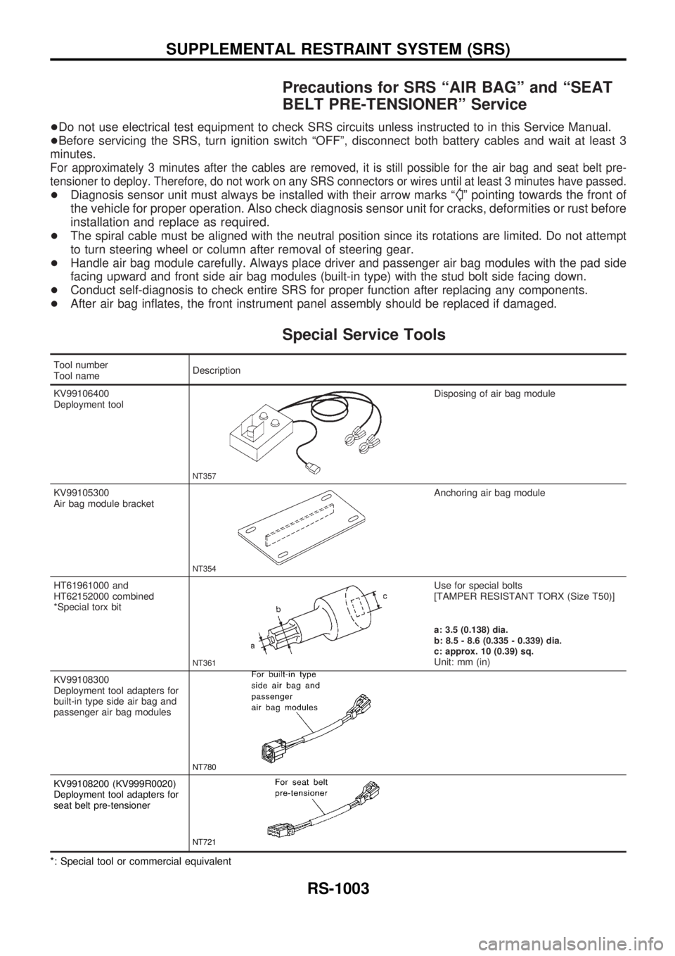
Special Service Tools
Tool number
Tool nameDescription
KV99106400
Deployment tool
NT357
Disposing of air bag module
KV99105300
Air bag module bracket
NT354
Anchoring air bag module
HT61961000 and
HT62152000 combined
*Special torx bit
NT361
Use for special bolts
[TAMPER RESISTANT TORX (Size T50)]
a: 3.5 (0.138) dia.
b: 8.5 - 8.6 (0.335 - 0.339) dia.
c: approx. 10 (0.39) sq.
Unit: mm (in)
KV99108300
Deployment tool adapters for
built-in type side air bag and
passenger air bag modules
NT780
KV99108200 (KV999R0020)
Deployment tool adapters for
seat belt pre-tensioner
NT721
*: Special tool or commercial equivalent
SUPPLEMENTAL RESTRAINT SYSTEM (SRS)
RS-1003