2000 NISSAN PATROL key
[x] Cancel search: keyPage 4 of 1033

Diagnostic Procedure....................................... 1088
TROUBLE DIAGNOSIS FOR CONTROL UNIT
(EFP ROM)........................................................... 1089
Description ....................................................... 1089
Diagnostic Procedure....................................... 1090
TROUBLE DIAGNOSIS FOR
NON-DETECTABLE ITEMS................................ 1091
PNP, Overdrive Control, A/T Mode or
Accelerator Position Switches ......................... 1091
DIAGNOSTIC PROCEDURES FOR
SYMPTOMS......................................................... 1097
1. SPORT Indicator Lamp Does Not
Come On.......................................................... 1097
2. SPORT Indicator Lamp Does Not
Come On.......................................................... 1098
3. O/D OFF Indicator Lamp Does Not Come
On .................................................................... 1098
4. SPORT Indicator Lamp Does Not
Come On.......................................................... 1099
5. Engine Cannot Be Started In ªPº and ªNº
Position ............................................................ 1100
6. In ªPº Position, Vehicle Moves Forward Or
Backward When Pushed ................................. 1100
7. In ªNº Position, Vehicle Moves .................... 1101
8. Large Shock. ªNº®ªRº Position ................ 1102
9. Vehicle Does Not Creep Backward In ªRº
Position ............................................................ 1103
10. Vehicle Does Not Creep Forward In ªDº,
ª2º Or ª1º Position ............................................ 1104
11. Vehicle Cannot Be Started From D
1......... 1105
12. A/T Does Not Shift: D
1®D2Or Does Not
Kickdown: D
4®D2......................................... 1106
13. A/T Does Not Shift: D
2®D3.................... 1107
14. A/T Does Not Shift: D
3®D4.................... 1108
15. A/T Does Not Perform Lock-up ................. 1109
16. A/T Does Not Hold Lock-up Condition ...... 1110
17. Lock-up Is Not Released ........................... 1110
18. Engine Speed Does Not Return To Idle
(Light Braking D
4®D3) .................................. 1111
19. Vehicle Does Not Start From D
1............... 1112
20. A/T Does Not Shift: D
2®D1When
Depressing Accelerator Pedal ......................... 1113
21. A/T Does Not Shift: D
4®D3, When
Overdrive Control Switch ªONº®ªOFFº ........ 1114
22. A/T Does Not Shift: D
3®22, When
Selector Lever ªDº®ª2º Position ................... 1114
23. A/T Does Not Shift: 2
2®11, WhenSelector Lever ª2º®ª1º Position .................... 1115
24. Vehicle Does Not Decelerate By Engine
Brake ................................................................ 1115
TROUBLE DIAGNOSES Ð A/T Shift Lock
System................................................................. 1116
Description ....................................................... 1116
Wiring Diagram Ð SHIFT Ð ........................... 1117
Diagnostic Procedure....................................... 1118
Key Interlock Cable.......................................... 1121
Component Check ........................................... 1122
ON-VEHICLE SERVICE...................................... 1124
Control Valve Assembly and Accumulators .... 1124
Revolution Sensor Replacement ..................... 1125
Rear Oil Seal Replacement ............................. 1125
Parking Pawl Components Inspection ............. 1125
PNP Switch Adjustment ................................... 1125
Manual Control Linkage Adjustment................ 1126
REMOVAL AND INSTALLATION....................... 1127
Removal ........................................................... 1127
Installation ........................................................ 1128
MAJOR OVERHAUL........................................... 1129
Oil Channel ...................................................... 1131
Locations of Needle Bearings, Thrust Washers
and Snap Rings ............................................... 1132
DISASSEMBLY.................................................... 1133
REPAIR FOR COMPONENT PARTS................. 1144
Oil Pump .......................................................... 1144
Control Valve Assembly................................... 1148
Control Valve Upper Body ............................... 1154
Control Valve Lower Body ............................... 1159
Reverse Clutch ................................................ 1161
High Clutch ...................................................... 1165
Forward and Overrun Clutches ....................... 1167
Low & Reverse Brake ...................................... 1171
Forward Clutch Drum Assembly ...................... 1175
Rear Internal Gear and Forward Clutch Hub .. 1177
Band Servo Piston Assembly .......................... 1180
Parking Pawl Components .............................. 1184
ASSEMBLY.......................................................... 1186
Assembly (1) .................................................... 1186
Adjustment ....................................................... 1190
Assembly (2) .................................................... 1195
A/T FLUID COOLER SYSTEM........................... 1205
A/T Fluid Cooler ............................................... 1205
SERVICE DATA AND SPECIFICATIONS (SDS)1206
General Specifications ..................................... 1206
Specifications and Adjustment......................... 1206
When you read wiring diagrams:
+Read GI section, ªHOW TO READ WIRING DIAGRAMSº.
+See EL section, ªPOWER SUPPLY ROUTINGº for power distribution circuit.
When you perform trouble diagnoses, read GI section, ªHOW TO FOLLOW FLOW
CHART IN TROUBLE DIAGNOSESº.
AT-1002
Page 8 of 1033
Service Notice or Precautions
FAIL-SAFE
The TCM has an electronic Fail-Safe (limp home mode). This allows the vehicle to be driven even if a major
electrical input/output device circuit is damaged.
Under Fail-Safe, the vehicle always runs in third gear even with a shift lever position of ª1º, ª2º or ªDº. Cus-
tomer may complain of ªsluggish or poor accelerationº.
When the Fail-Safe operation occurs the next time the key is turned to the ªONº position, the SPORT indi-
cator lamp will blink for about 8 seconds. (For diagnosis, refer to AT-1029.)
The blinking of the SPORT indicator lamp for about 8 seconds will appear only once and be cleared. The
customer may resume normal driving conditions by chance.
Always follow the ªWORK FLOWº (Refer to AT-1040).
The SELF-DIAGNOSIS results will be as follows:
The first SELF-DIAGNOSIS will indicate the damage of the vehicle speed sensor or the revolution
sensor.
During the next SELF-DIAGNOSIS performed after checking the sensor, no damages will be indicated.
PREPARATION AND PRECAUTIONS
AT-1006
Page 39 of 1033
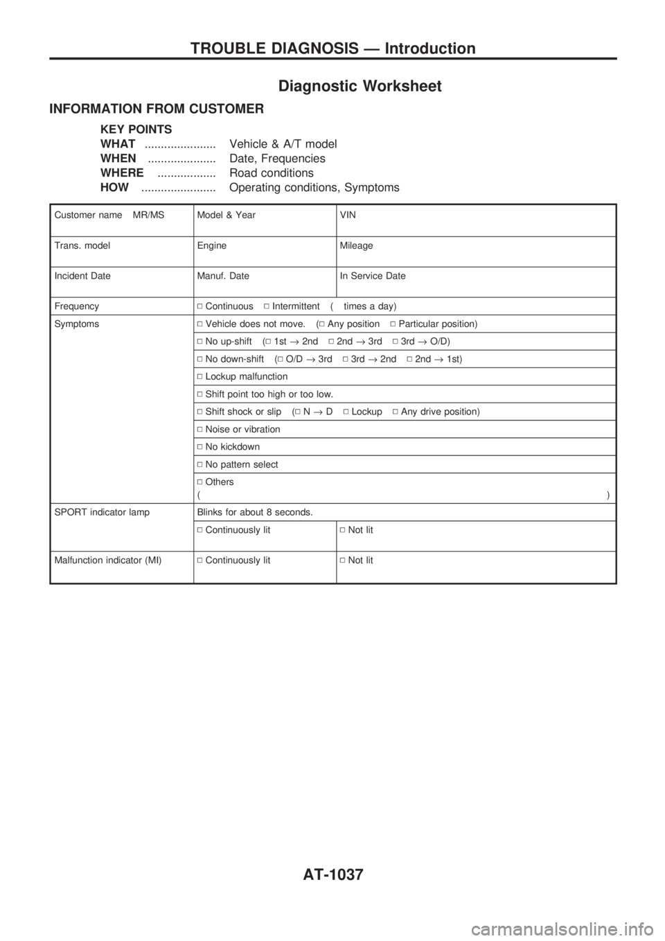
Diagnostic Worksheet
INFORMATION FROM CUSTOMER
KEY POINTS
WHAT...................... Vehicle & A/T model
WHEN..................... Date, Frequencies
WHERE.................. Road conditions
HOW....................... Operating conditions, Symptoms
Customer name MR/MS Model & Year VIN
Trans. model Engine Mileage
Incident Date Manuf. Date In Service Date
FrequencyNContinuousNIntermittent ( times a day)
SymptomsNVehicle does not move. (NAny positionNParticular position)
NNo up-shift (N1st®2ndN2nd®3rdN3rd®O/D)
NNo down-shift (NO/D®3rdN3rd®2ndN2nd®1st)
NLockup malfunction
NShift point too high or too low.
NShift shock or slip (NN®DNLockupNAny drive position)
NNoise or vibration
NNo kickdown
NNo pattern select
NOthers
()
SPORT indicator lamp Blinks for about 8 seconds.
NContinuously litNNot lit
Malfunction indicator (MI)NContinuously litNNot lit
TROUBLE DIAGNOSIS Ð Introduction
AT-1037
Page 98 of 1033
Accelerator position switch
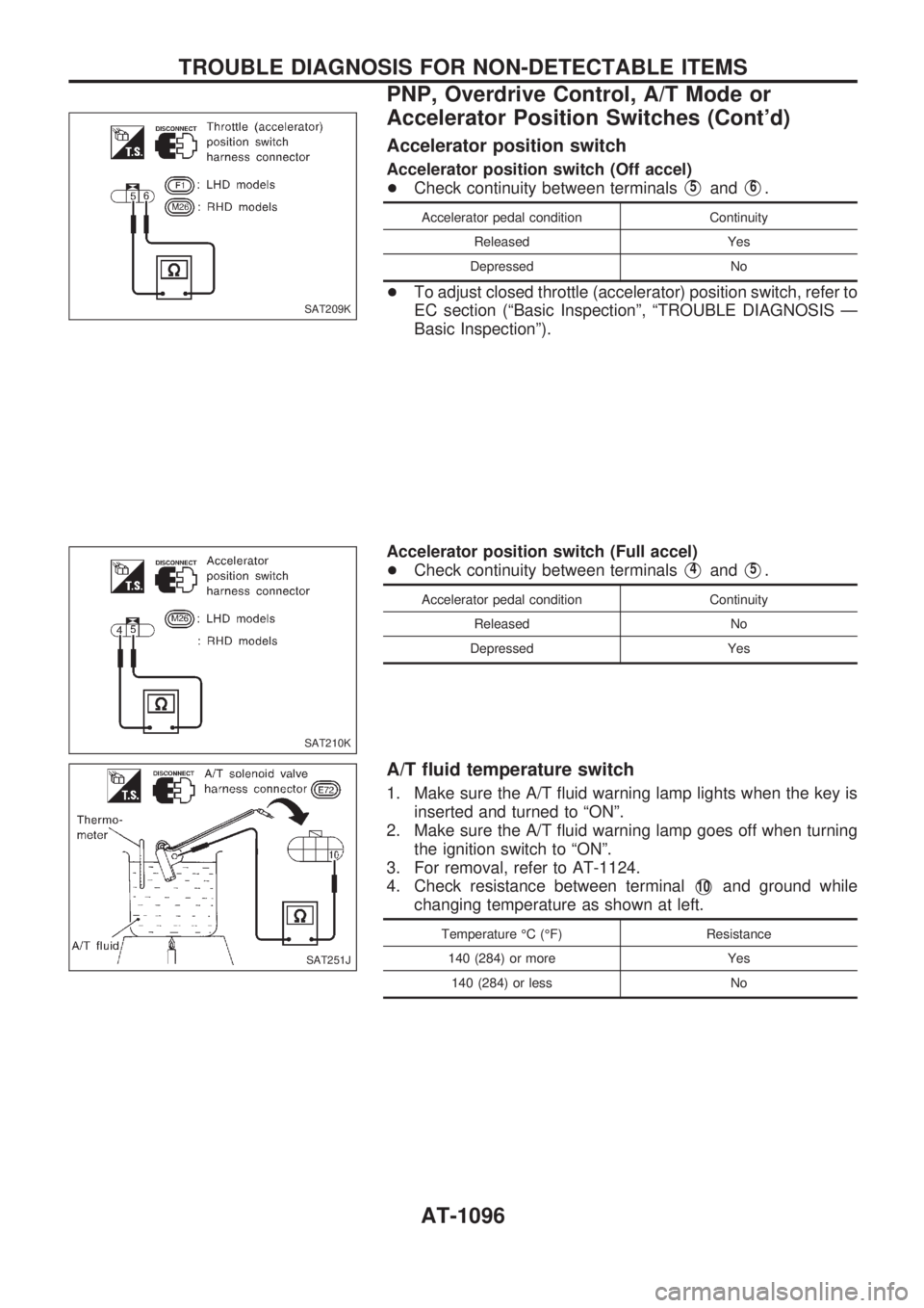
Accelerator position switch (Off accel)
+Check continuity between terminals
V5andV6.
Accelerator pedal condition Continuity
Released Yes
Depressed No
+To adjust closed throttle (accelerator) position switch, refer to
EC section (ªBasic Inspectionº, ªTROUBLE DIAGNOSIS Ð
Basic Inspectionº).
Accelerator position switch (Full accel)
+Check continuity between terminals
V4andV5.
Accelerator pedal condition Continuity
Released No
Depressed Yes
A/T fluid temperature switch
1. Make sure the A/T fluid warning lamp lights when the key is
inserted and turned to ªONº.
2. Make sure the A/T fluid warning lamp goes off when turning
the ignition switch to ªONº.
3. For removal, refer to AT-1124.
4. Check resistance between terminal
V10and ground while
changing temperature as shown at left.
Temperature ÉC (ÉF) Resistance
140 (284) or more Yes
140 (284) or less No
SAT209K
SAT210K
SAT251J
TROUBLE DIAGNOSIS FOR NON-DETECTABLE ITEMS
PNP, Overdrive Control, A/T Mode or
Accelerator Position Switches (Cont'd)
AT-1096
Page 118 of 1033
Description
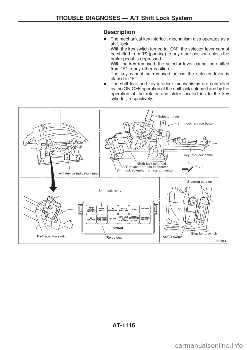
+The mechanical key interlock mechanism also operates as a
shift lock:
With the key switch turned to ªONº, the selector lever cannot
be shifted from ªPº (parking) to any other position unless the
brake pedal is depressed.
With the key removed, the selector lever cannot be shifted
from ªPº to any other position.
The key cannot be removed unless the selector lever is
placed in ªPº.
+The shift lock and key interlock mechanisms are controlled
by the ON-OFF operation of the shift lock solenoid and by the
operation of the rotator and slider located inside the key
cylinder, respectively.
SAT914J
TROUBLE DIAGNOSES Ð A/T Shift Lock System
AT-1116
Page 120 of 1033
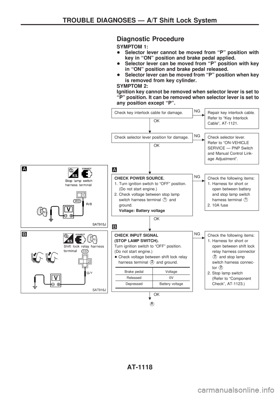
Diagnostic Procedure
SYMPTOM 1:
+Selector lever cannot be moved from ªPº position with
key in ªONº position and brake pedal applied.
+Selector lever can be moved from ªPº position with key
in ªONº position and brake pedal released.
+Selector lever can be moved from ªPº position when key
is removed from key cylinder.
SYMPTOM 2:
Ignition key cannot be removed when selector lever is set to
ªPº position. It can be removed when selector lever is set to
any position except ªPº.
Check key interlock cable for damage.
OK
cNG
Repair key interlock cable.
Refer to ªKey Interlock
Cableº, AT-1121.
Check selector lever position for damage.
OK
cNG
Check selector lever.
Refer to ªON-VEHICLE
SERVICE Ð PNP Switch
and Manual Control Link-
age Adjustmentº.
CHECK POWER SOURCE.
1. Turn ignition switch to ªOFFº position.
(Do not start engine.)
2. Check voltage between stop lamp
switch harness terminal
V1and
ground.
Voltage: Battery voltage
OK
cNG
Check the following items:
1. Harness for short or
open between battery
and stop lamp switch
harness terminal
V1
2. 10A fuse
CHECK INPUT SIGNAL
(STOP LAMP SWITCH).
Turn ignition switch to ªOFFº position.
(Do not start engine.)
+Check voltage between shift lock relay
harness terminal
V2and ground.
OK
cNG
Check the following items:
1. Harness for short or
open between shift lock
relay harness connector
V2and stop lamp
switch harness connec-
tor
V2
2. Stop lamp switch
(Refer to ªComponent
Checkº, AT-1123.)
VA
Brake pedal Voltage
Released 0V
Depressed Battery voltage
SAT915J
SAT916J
.
.
.
.
TROUBLE DIAGNOSES Ð A/T Shift Lock System
AT-1118
Page 123 of 1033
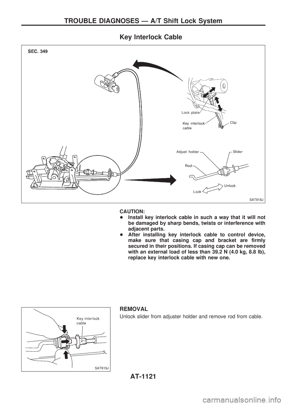
Key Interlock Cable
CAUTION:
+Install key interlock cable in such a way that it will not
be damaged by sharp bends, twists or interference with
adjacent parts.
+After installing key interlock cable to control device,
make sure that casing cap and bracket are firmly
secured in their positions. If casing cap can be removed
with an external load of less than 39.2 N (4.0 kg, 8.8 lb),
replace key interlock cable with new one.
REMOVAL
Unlock slider from adjuster holder and remove rod from cable.
SAT918J
SAT919J
TROUBLE DIAGNOSES Ð A/T Shift Lock System
AT-1121
Page 124 of 1033
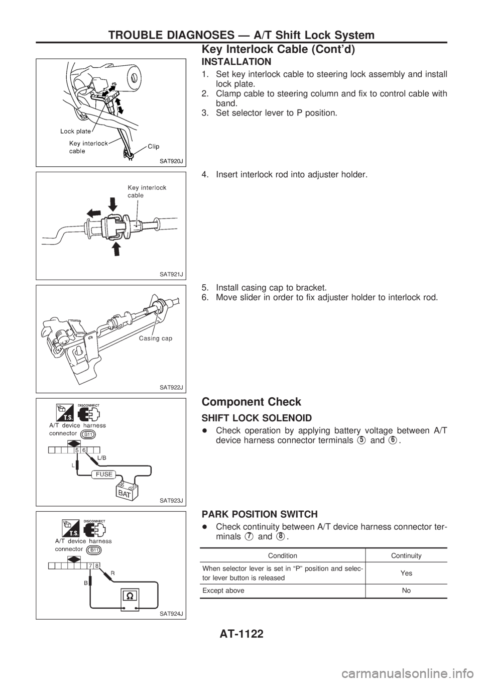
INSTALLATION
1. Set key interlock cable to steering lock assembly and install
lock plate.
2. Clamp cable to steering column and fix to control cable with
band.
3. Set selector lever to P position.
4. Insert interlock rod into adjuster holder.
5. Install casing cap to bracket.
6. Move slider in order to fix adjuster holder to interlock rod.
Component Check
SHIFT LOCK SOLENOID
+Check operation by applying battery voltage between A/T
device harness connector terminals
V5andV6.
PARK POSITION SWITCH
+Check continuity between A/T device harness connector ter-
minals
V7andV8.
Condition Continuity
When selector lever is set in ªPº position and selec-
tor lever button is releasedYes
Except above No
SAT920J
SAT921J
SAT922J
SAT923J
SAT924J
TROUBLE DIAGNOSES Ð A/T Shift Lock System
Key Interlock Cable (Cont'd)
AT-1122