2000 NISSAN PATROL key
[x] Cancel search: keyPage 664 of 1033
Trouble Diagnoses
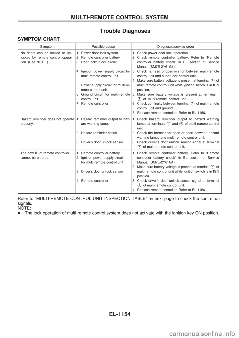
SYMPTOM CHART
Symptom Possible cause Diagnoses/service order
No doors can be locked or un-
locked by remote control opera-
tion. (See NOTE.)1. Power door lock system
2. Remote controller battery
3. Door lock/unlock circuit
4. Ignition power supply circuit for
multi-remote control unit
5. Power supply circuit for multi-re-
mote control unit
6. Ground circuit for multi-remote
control unit
7. Remote controller1. Check power door lock operation.
2. Check remote controller battery. Refer to ªRemote
controller battery checkº in EL section of Service
Manual (SM7E-2Y61G1).
3. Check harness for open or short between multi-remote
control unit and super lock control unit.
4. Make sure battery voltage is present at terminal
V4of
multi-remote control unit while ignition switch is in IGN
position.
5. Make sure battery voltage is present at terminal
V2of multi-remote control unit.
6. Check continuity between terminal
V1of multi-remote
control unit and ground.
7. Replace remote controller. Refer to EL-1156.
Hazard reminder does not operate
properly.1. Hazard reminder output to haz-
ard warning lamps
2. Hazard reminder circuit
3. Driver's door unlock sensor1. Check hazard reminder output to hazard warning
lamps at terminals
V3andV8of multi-remote control
unit.
2. Check the harness for open or short between hazard
warning lamps and multi-remote control unit.
3. Check driver's door unlock sensor signal at terminal
V7of multi-remote control unit.
The new ID of remote controller
cannot be entered.1. Remote controller battery
2. Ignition power supply circuit
for multi-remote control unit
3. Driver's door unlock sensor
4. Remote controller1. Check remote controller battery. Refer to ªRemote
controller battery checkº in EL section of Service
Manual (SM7E-2Y61G1).
2. Make sure battery voltage is present at terminal
V4of
multi-remote control unit while ignition switch is in IGN
position.
3. Check driver's door unlock sensor signal at terminal
V7of multi-remote control unit.
4. Replace remote controller. Refer to EL-1156.
Refer to ªMULTI-REMOTE CONTROL UNIT INSPECTION TABLEº on next page to check the control unit
signals.
NOTE:
+The lock operation of multi-remote control system does not activate with the ignition key ON position.
MULTI-REMOTE CONTROL SYSTEM
EL-1154
Page 665 of 1033
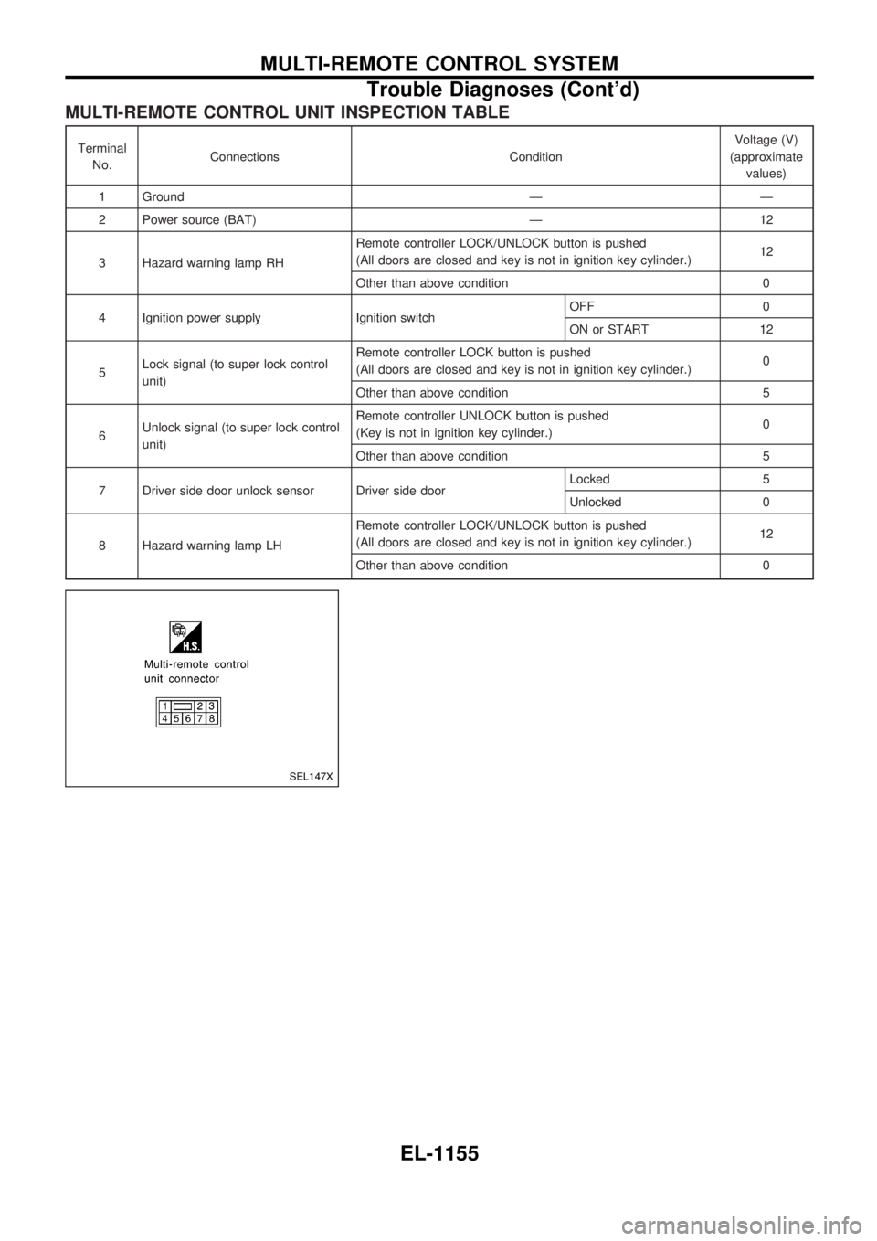
MULTI-REMOTE CONTROL UNIT INSPECTION TABLE
Terminal
No.Connections ConditionVoltage (V)
(approximate
values)
1 Ground Ð Ð
2 Power source (BAT) Ð 12
3 Hazard warning lamp RHRemote controller LOCK/UNLOCK button is pushed
(All doors are closed and key is not in ignition key cylinder.)12
Other than above condition 0
4 Ignition power supply Ignition switchOFF 0
ON or START 12
5Lock signal (to super lock control
unit)Remote controller LOCK button is pushed
(All doors are closed and key is not in ignition key cylinder.)0
Other than above condition 5
6Unlock signal (to super lock control
unit)Remote controller UNLOCK button is pushed
(Key is not in ignition key cylinder.)0
Other than above condition 5
7 Driver side door unlock sensor Driver side doorLocked 5
Unlocked 0
8 Hazard warning lamp LHRemote controller LOCK/UNLOCK button is pushed
(All doors are closed and key is not in ignition key cylinder.)12
Other than above condition 0
SEL147X
MULTI-REMOTE CONTROL SYSTEM
Trouble Diagnoses (Cont'd)
EL-1155
Page 666 of 1033
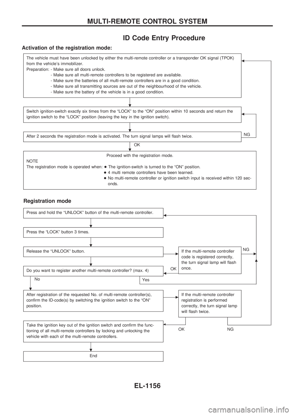
ID Code Entry Procedure
Activation of the registration mode:
The vehicle must have been unlocked by either the multi-remote controller or a transponder OK signal (TPOK)
from the vehicle's immobilizer.
Preparation: - Make sure all doors unlock.
- Make sure all multi-remote controllers to be registered are available.
- Make sure the batteries of all multi-remote controllers are in a good condition.
- Make sure all transmitting sources are out of the neighbourhood of the vehicle.
- Make sure the battery of the vehicle is in a good condition.b
Switch ignition-switch exactly six times from the ªLOCKº to the ªONº position within 10 seconds and return the
ignition switch to the ªLOCKº position (leaving the key in the ignition switch).b
After 2 seconds the registration mode is activated. The turn signal lamps will flash twice.
OKNG
Proceed with the registration mode.
NOTE
The registration mode is operated when:+The ignition-switch is turned to the ªONº position.
+4 multi remote controllers have been learned.
+No multi-remote controller or ignition switch input is received within 120 sec-
onds.
Registration mode
Press and hold the ªUNLOCKº button of the multi-remote controller.b
Press the ªLOCKº button 3 times.
Release the ªUNLOCKº button.cIf the multi-remote controller
code is registered correctly,
the turn signal lamp will flash
once.cNG
Do you want to register another multi-remote controller? (max. 4)
No
Yes
bOK
m
After registration of the requested No. of multi-remote controller(s),
confirm the ID-code(s) by switching the ignition switch to the ªONº
position.cIf the multi-remote controller
registration is performed
correctly, the turn signal lamp
will flash twice.
Take the ignition key out of the ignition switch and confirm the func-
tioning of all multi-remote controllers by locking and unlocking the
vehicle with each of the multi-remote controllers.b
OKNG
End
.
.
.
.
.
.
.
.
MULTI-REMOTE CONTROL SYSTEM
EL-1156
Page 669 of 1033
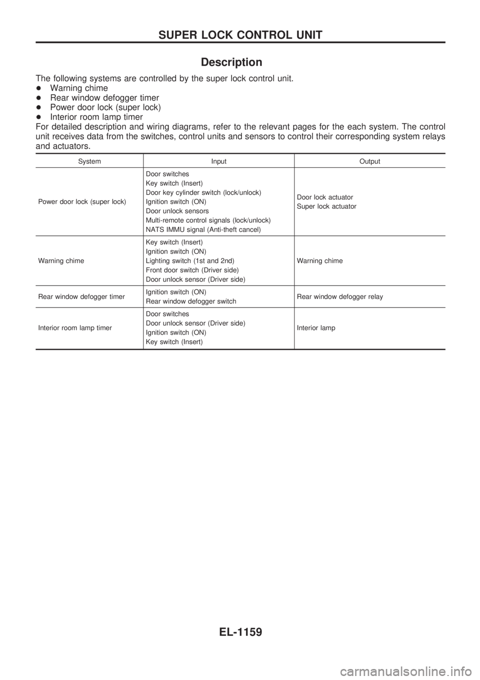
Description
The following systems are controlled by the super lock control unit.
+Warning chime
+Rear window defogger timer
+Power door lock (super lock)
+Interior room lamp timer
For detailed description and wiring diagrams, refer to the relevant pages for the each system. The control
unit receives data from the switches, control units and sensors to control their corresponding system relays
and actuators.
System Input Output
Power door lock (super lock)Door switches
Key switch (Insert)
Door key cylinder switch (lock/unlock)
Ignition switch (ON)
Door unlock sensors
Multi-remote control signals (lock/unlock)
NATS IMMU signal (Anti-theft cancel)Door lock actuator
Super lock actuator
Warning chimeKey switch (Insert)
Ignition switch (ON)
Lighting switch (1st and 2nd)
Front door switch (Driver side)
Door unlock sensor (Driver side)Warning chime
Rear window defogger timerIgnition switch (ON)
Rear window defogger switchRear window defogger relay
Interior room lamp timerDoor switches
Door unlock sensor (Driver side)
Ignition switch (ON)
Key switch (Insert)Interior lamp
SUPER LOCK CONTROL UNIT
EL-1159
Page 672 of 1033
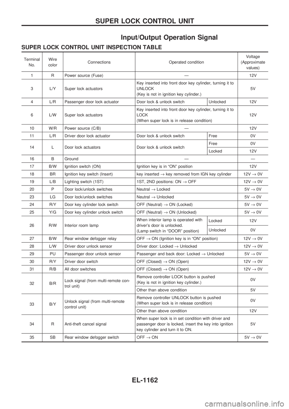
Input/Output Operation Signal
SUPER LOCK CONTROL UNIT INSPECTION TABLE
Terminal
No.Wire
colorConnections Operated conditionVoltage
(Approximate
values)
1 R Power source (Fuse) Ð 12V
3 L/Y Super lock actuatorsKey inserted into front door key cylinder, turning it to
UNLOCK
(Key is not in ignition key cylinder.)5V
4 L/R Passenger door lock actuator Door lock & unlock switch Unlocked 12V
6 L/W Super lock actuatorsKey inserted into front door key cylinder, turning it to
LOCK
(When super lock is in release condition)12V
10 W/R Power source (C/B) Ð 12V
11 L/R Driver door lock actuator Door lock & unlock switch Free 0V
14 L Door lock actuators Door lock & unlock switchFree 0V
Locked 12V
16 B Ground Ð Ð
17 B/W Ignition switch (ON) Ignition key is in ªONº position 12V
18 BR Ignition key switch (Insert) key inserted®key removed from IGN key cylinder 12V®0V
19 L/B Lighting switch (1ST) 1ST, 2ND positions: ON®OFF 12V®0V
20 P Door lock/unlock switches Neutral®Locked 5V®0V
23 LG Door lock/unlock switches Neutral®Unlocked 5V®0V
24 R/Y Door key cylinder lock switch OFF (Neutral)®ON (Locked) 5V®0V
25 Y/G Door key cylinder unlock switch OFF (Neutral)®ON (Unlocked) 5V®0V
26 R/W Interior room lampWhen interior lamp is operated with
driver's door is unlocked.
(Lamp switch in ªDOORº position)Locked 12V
Unlocked 0V
27 B/W Rear window defogger relay OFF®ON (Ignition key is in ªONº position) 12V®0V
28 L/W Driver door unlock sensor Driver door: Locked®Unlocked 12V®0V
29 PU Passenger door unlock sensor Passenger and back door: Locked®Unlocked 5V®0V
30 R/Y Driver door switch OFF (Closed)®ON (Open) 12V®0V
31 R/B All door switches OFF (Closed)®ON (Open) 12V®0V
32 B/RLock signal (from multi-remote con-
trol unit)Remove controller LOCK button is pushed
(Key is not in ignition key cylinder.)0V
Other than above condition 5V
33 B/YUnlock signal (from multi-remote
control unit)Remove controller UNLOCK button is pushed
(When super lock is in release condition)0V
Other than above condition 12V
34 R Anti-theft cancel signalWhen super lock is in set condition with driver and
passenger door is locked, insert the key into ignition
key cylinder and turn it to ON.5V
35 SB Rear window defogger switch OFF®ON 5V®0V
SUPER LOCK CONTROL UNIT
EL-1162
Page 673 of 1033
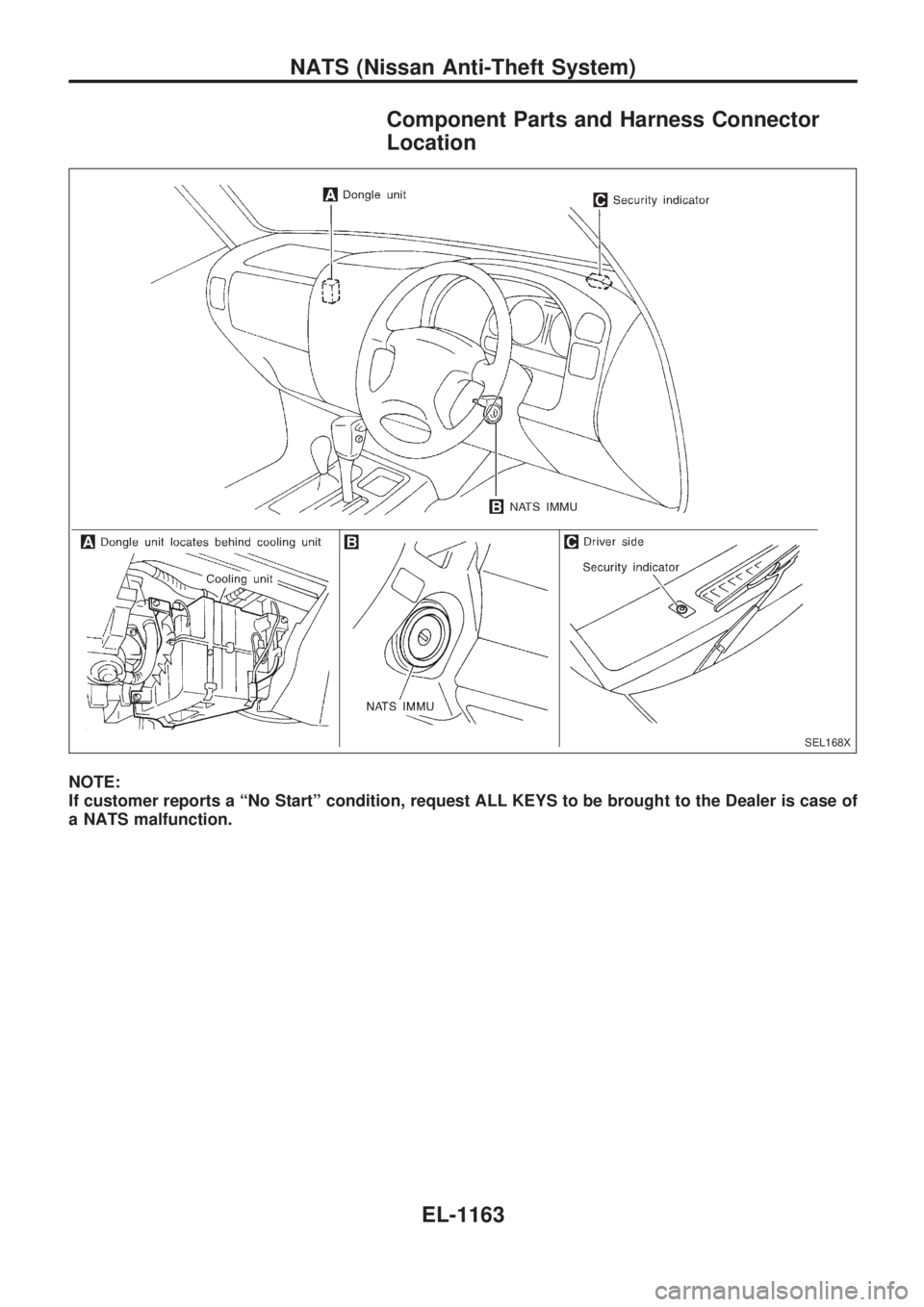
Component Parts and Harness Connector
Location
NOTE:
If customer reports a ªNo Startº condition, request ALL KEYS to be brought to the Dealer is case of
a NATS malfunction.
SEL168X
NATS (Nissan Anti-Theft System)
EL-1163
Page 674 of 1033
System Description
NATS has the following immobilizer functions:
+Since only NATS ignition keys, whose ID nos. have been registered into the ECM and IMMU of NATS,
allow the engine to run, operation of a stolen vehicle without a NATS registered key is prevented by
NATS.
That is to say, NATS will immobilize the engine if someone tries to start it without the registered key of
NATS.
+This version of NATS has dongle unit to improve its anti-theft performance (RHD models). Dongle unit
has its own ID which is registered into NATS IMMU. So it dongle unit is replaced, initialization must be
carried out.
+When malfunction of dongle unit is detected:
Ð The security indicator lamp illuminates for about 15 minutes after ignition switch is turned to ON.
Ð When dongle unit has a malfunction and the indicator lamp is illuminated, engine can not be started.
However, engine can be started only one time when security indicator turns off in about 15 minutes
after ignition switch is turned to ON.
+Both of the originally supplied ignition key IDs have been NATS registered.
If requested by the vehicle owner, a maximum of five key IDs can be registered into the NATS compo-
nents.
+The NATS security indicator (NATS security ind.) blinks when the ignition switch is in ªOFFº or ªACCº
position. Therefore, NATS warns outsiders that the vehicle is equipped with the anti-theft system.
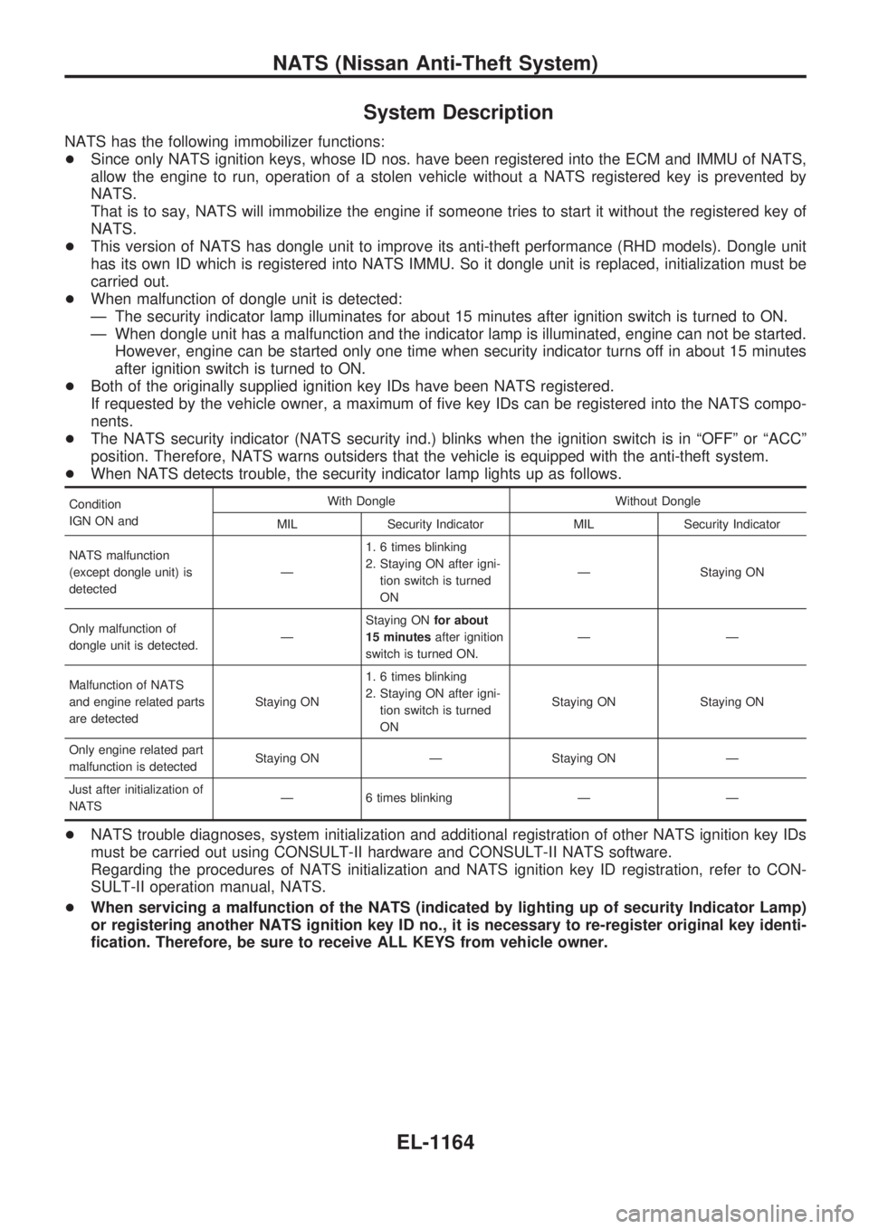
+When NATS detects trouble, the security indicator lamp lights up as follows.
Condition
IGN ON andWith Dongle Without Dongle
MIL Security Indicator MIL Security Indicator
NATS malfunction
(except dongle unit) is
detectedÐ1. 6 times blinking
2. Staying ON after igni-
tion switch is turned
ONÐ Staying ON
Only malfunction of
dongle unit is detected.ÐStaying ONfor about
15 minutesafter ignition
switch is turned ON.ÐÐ
Malfunction of NATS
and engine related parts
are detectedStaying ON1. 6 times blinking
2. Staying ON after igni-
tion switch is turned
ONStaying ON Staying ON
Only engine related part
malfunction is detectedStaying ON Ð Staying ON Ð
Just after initialization of
NATSÐ 6 times blinking Ð Ð
+NATS trouble diagnoses, system initialization and additional registration of other NATS ignition key IDs
must be carried out using CONSULT-II hardware and CONSULT-II NATS software.
Regarding the procedures of NATS initialization and NATS ignition key ID registration, refer to CON-
SULT-II operation manual, NATS.
+When servicing a malfunction of the NATS (indicated by lighting up of security Indicator Lamp)
or registering another NATS ignition key ID no., it is necessary to re-register original key identi-
fication. Therefore, be sure to receive ALL KEYS from vehicle owner.
NATS (Nissan Anti-Theft System)
EL-1164
Page 675 of 1033
System Composition
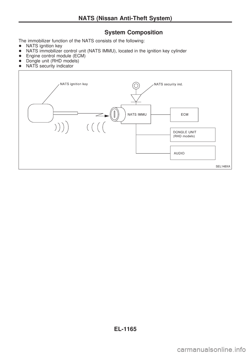
The immobilizer function of the NATS consists of the following:
+NATS ignition key
+NATS immobilizer control unit (NATS IMMU), located in the ignition key cylinder
+Engine control module (ECM)
+Dongle unit (RHD models)
+NATS security indicator
SEL148XA
NATS (Nissan Anti-Theft System)
EL-1165