Page 635 of 1033
System Description
OUTLINE
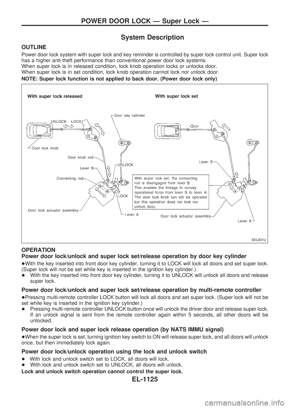
Power door lock system with super lock and key reminder is controlled by super lock control unit. Super lock
has a higher anti-theft performance than conventional power door lock systems.
When super lock is in released condition, lock knob operation locks or unlocks door.
When super lock is in set condition, lock knob operation cannot lock nor unlock door.
NOTE: Super lock function is not applied to back door. (Power door lock only)
OPERATION
Power door lock/unlock and super lock set/release operation by door key cylinder
+With the key inserted into front door key cylinder, turning it to LOCK will lock all doors and set super lock.
(Super lock will not be set while key is inserted in the ignition key cylinder.)
+With the key inserted into front door key cylinder, turning it to UNLOCK will unlock all doors and release
super lock.
Power door lock/unlock and super lock set/release operation by multi-remote controller
+Pressing multi-remote controller LOCK button will lock all doors and set super lock. (Super lock will not be
set while key is inserted in the ignition key cylinder.)
+Pressing multi-remote controller UNLOCK button once will unlock the driver door and release super lock.
If an unlock signal is sent from the remote controller again within 5 seconds, all other doors will be
unlocked.
Power door lock and super lock release operation (by NATS IMMU signal)
+When the super lock is set, turning ignition key switch to ON will release super lock, and all doors will unlock
once, but then immediately lock again.
Power door lock/unlock operation using the lock and unlock switch
+With lock and unlock switch set to LOCK, all doors will lock.
+With lock and unlock switch set to UNLOCK, all doors will unlock.
Lock and unlock switch operation cannot control the super lock.
SEL831U
POWER DOOR LOCK Ð Super Lock Ð
EL-1125
Page 636 of 1033
Key reminder system
+If the ignition key is in the ignition key cylinder and the driver door is open, setting lock knob on driver door,
key or multi-remote controller to ªLOCKº locks the door once but then immediately unlocks all doors. (Sig-
nal from unlock sensor driver side)
System initialization
+System initialization is required when battery cables are reconnected. Conduct one of the followings to
release super lock once;
Ð insert the key into ignition key cylinder and turn it to ON.
Ð LOCK/UNLOCK operation using door key cylinder or multi-remote controller.
POWER DOOR LOCK Ð Super Lock Ð
System Description (Cont'd)
EL-1126
Page 648 of 1033
Trouble Diagnoses
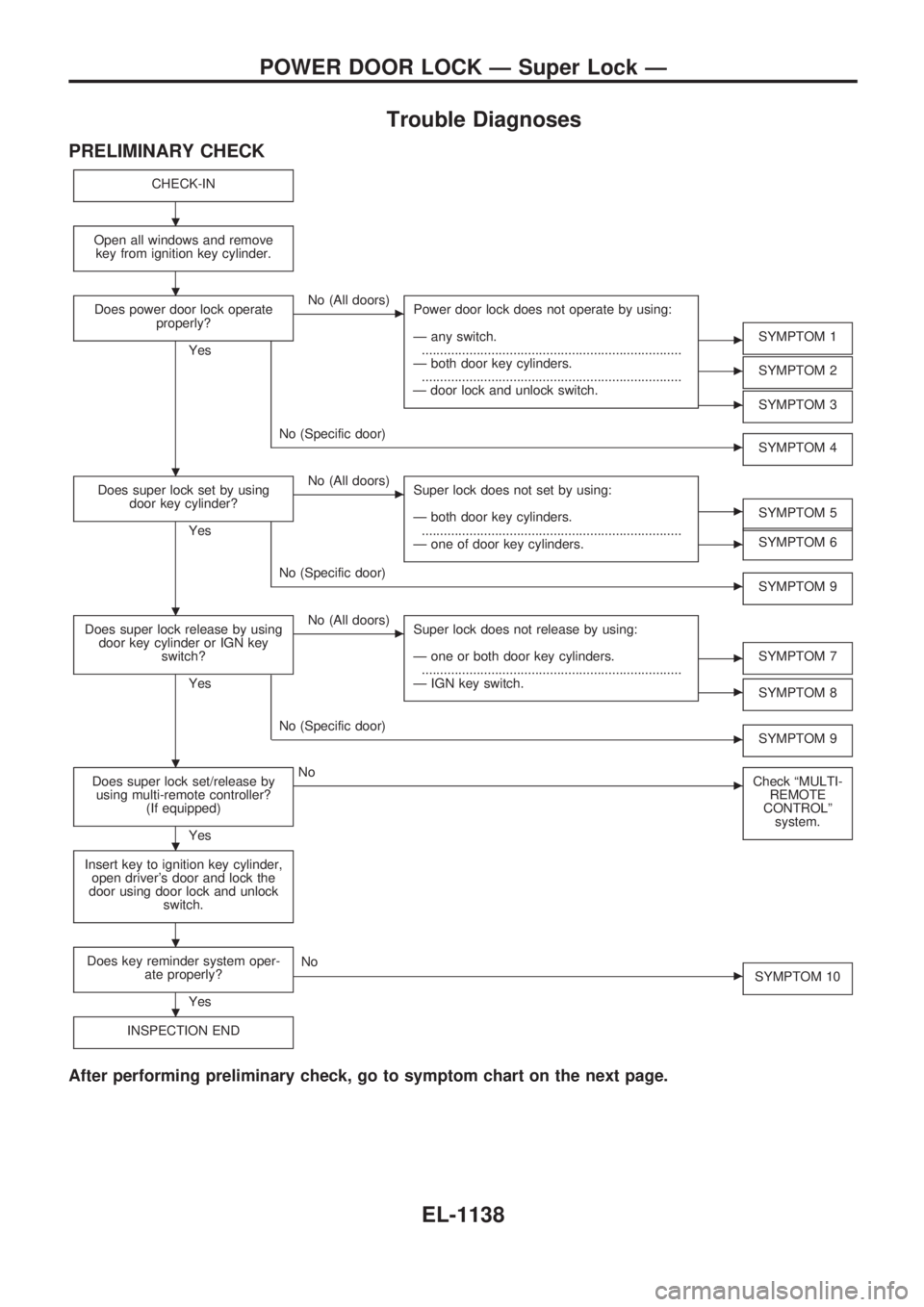
PRELIMINARY CHECK
CHECK-IN
Open all windows and remove
key from ignition key cylinder.
Does power door lock operate
properly?
Yes
cNo (All doors)
Power door lock does not operate by using:
Ð any switch.
.......................................................................
Ð both door key cylinders.
.......................................................................
Ð door lock and unlock switch.
cSYMPTOM 1
cSYMPTOM 2
cSYMPTOM 3
cNo (Specific door)
SYMPTOM 4
Does super lock set by using
door key cylinder?
Yes
cNo (All doors)
Super lock does not set by using:
Ð both door key cylinders.
.......................................................................
Ð one of door key cylinders.
cSYMPTOM 5
cSYMPTOM 6
cNo (Specific door)
SYMPTOM 9
Does super lock release by using
door key cylinder or IGN key
switch?
Yes
cNo (All doors)
Super lock does not release by using:
Ð one or both door key cylinders.
.......................................................................
Ð IGN key switch.
cSYMPTOM 7
cSYMPTOM 8
cNo (Specific door)
SYMPTOM 9
Does super lock set/release by
using multi-remote controller?
(If equipped)
Yes
cNo
Check ªMULTI-
REMOTE
CONTROLº
system.
Insert key to ignition key cylinder,
open driver's door and lock the
door using door lock and unlock
switch.
Does key reminder system oper-
ate properly?
Yes
cNo
SYMPTOM 10
INSPECTION END
After performing preliminary check, go to symptom chart on the next page.
.
.
.
.
.
.
.
.
POWER DOOR LOCK Ð Super Lock Ð
EL-1138
Page 649 of 1033
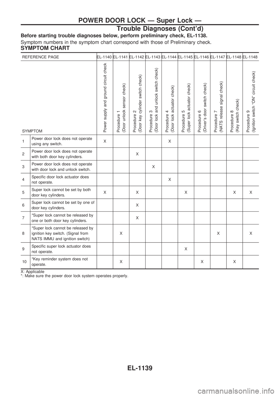
Before starting trouble diagnoses below, perform preliminary check, EL-1138.
Symptom numbers in the symptom chart correspond with those of Preliminary check.
SYMPTOM CHART
REFERENCE PAGE EL-1140 EL-1141 EL-1142 EL-1143 EL-1144 EL-1145 EL-1146 EL-1147 EL-1148 EL-1148
SYMPTOM
Power supply and ground circuit check
Procedure 1
(Door unlock sensor check)
Procedure 2
(Door key cylinder switch check)
Procedure 3
(Door lock and unlock switch check)
Procedure 4
(Door lock actuator check)
Procedure 5
(Super lock actuator check)
Procedure 6
(Driver's door switch check)
Procedure 7
(NATS release signal check)
Procedure 8
(Key switch check)
Procedure 9
(Ignition switch ªONº circuit check)
1Power door lock does not operate
using any switch.XX
2Power door lock does not operate
with both door key cylinders.X
3Power door lock does not operate
with door lock and unlock switch.X
4Specific door lock actuator does
not operate.X
5Super lock cannot be set by both
door key cylinders.XXXXX
6Super lock cannot be set by one of
door key cylinders.X
7*Super lock cannot be released by
one or both door key cylinders.X
8*Super lock cannot be released by
ignition key switch. (Signal from
NATS IMMU and ignition switch)XXX
9Specific super lock actuator does
not operate.X
10*Key reminder system does not
operate.XXX
X: Applicable
*: Make sure the power door lock system operates properly.
POWER DOOR LOCK Ð Super Lock Ð
Trouble Diagnoses (Cont'd)
EL-1139
Page 652 of 1033
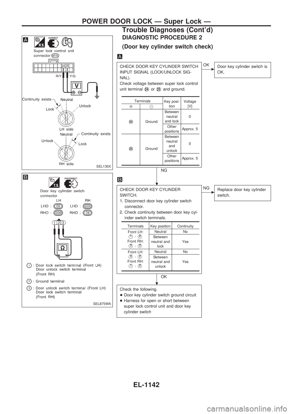
DIAGNOSTIC PROCEDURE 2
(Door key cylinder switch check)
CHECK DOOR KEY CYLINDER SWITCH
INPUT SIGNAL (LOCK/UNLOCK SIG-
NAL).
Check voltage between super lock control
unit terminal
V24orV25and ground.
NG
cOK
Door key cylinder switch is
OK.
CHECK DOOR KEY CYLINDER
SWITCH.
1. Disconnect door key cylinder switch
connector.
2. Check continuity between door key cyl-
inder switch terminals.
OK
cNG
Replace door key cylinder
switch.
Check the following.
+Door key cylinder switch ground circuit
+Harness for open or short between
super lock control unit and door key
cylinder switch
Terminals
Key posi-
tionVoltage
[V]
Å@
V24GroundBetween
neutral
and lock0
Other
positionsApprox. 5
V25GroundBetween
neutral
and
unlock0
Other
positionsApprox. 5
Terminals Key position Continuity
Front LH:
V1-V2
Front RH:
V3-V2
Neutral No
Between
neutral and
lockYes
Front LH:
V3-V2
Front RH:
V1-V2
Neutral No
Between
neutral and
unlockYes
SEL135X
SEL875WA
.
.
POWER DOOR LOCK Ð Super Lock Ð
Trouble Diagnoses (Cont'd)
EL-1142
Page 655 of 1033
DIAGNOSTIC PROCEDURE 5
[Super lock actuator (in door lock actuator assembly)
check]
CHECK OUTPUT SIGNAL FOR SUPER
LOCK ACTUATOR.
Check voltage for super lock actuator.
Put the system in set condition before
checking release signal.
Refer to wiring diagram in EL-1131
(LHD), EL-1136 (RHD).
OK
cNG
Super lock actuator is OK.
CHECK SUPER LOCK ACTUATOR.
1. Disconnect door lock actuator assem-
bly connector.
2. Set lever A in Lock position.
3. Apply 12V direct current to door lock
actuator assembly and check opera-
tion.
NG
cOK
Check harness between
control unit and door lock
actuator assembly.
Replace door lock actuator assembly.
Door key cylin-
der switch con-
ditionTerminals
Voltage
(V)
Å@
Lock (Set)
V6Ground
Approx. 12
Unlock
(Released)
V3Ground
Super lock
actuator opera-
tionTermi-
nalsConnection from
lever B to lever
A
Å@
Released®Set
V1V4Disconnect
Set®Released
V4V1Connect
SEL139X
SEL820UB
.
.
POWER DOOR LOCK Ð Super Lock Ð
Trouble Diagnoses (Cont'd)
EL-1145
Page 658 of 1033
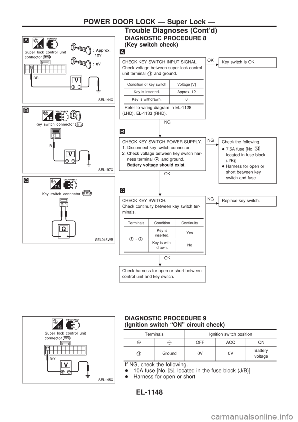
DIAGNOSTIC PROCEDURE 8
(Key switch check)
CHECK KEY SWITCH INPUT SIGNAL.
Check voltage between super lock control
unit terminal
V18and ground.
Refer to wiring diagram in EL-1128
(LHD), EL-1133 (RHD).
NG
cOK
Key switch is OK.
CHECK KEY SWITCH POWER SUPPLY.
1. Disconnect key switch connector.
2. Check voltage between key switch har-
ness terminal
V2and ground.
Battery voltage should exist.
OK
cNG
Check the following.
+7.5A fuse [No.
24,
located in fuse block
(J/B)]
+Harness for open or
short between key
switch and fuse
CHECK KEY SWITCH.
Check continuity between key switch ter-
minals.
OK
cNG
Replace key switch.
Check harness for open or short between
control unit and key switch.
Condition of key switch Voltage [V]
Key is inserted. Approx. 12
Key is withdrawn. 0
Terminals Condition Continuity
V1-V2
Key is
inserted.Yes
Key is with-
drawn.No
DIAGNOSTIC PROCEDURE 9
(Ignition switch ªONº circuit check)
Terminals Ignition switch position
Å@OFF ACC ON
V17Ground 0V 0VBattery
voltage
If NG, check the following.
+10A fuse [No.
25, located in the fuse block (J/B)]
+Harness for open or short
SEL144X
SEL197X
SEL015WB
SEL145X
.
.
.
POWER DOOR LOCK Ð Super Lock Ð
Trouble Diagnoses (Cont'd)
EL-1148
Page 659 of 1033
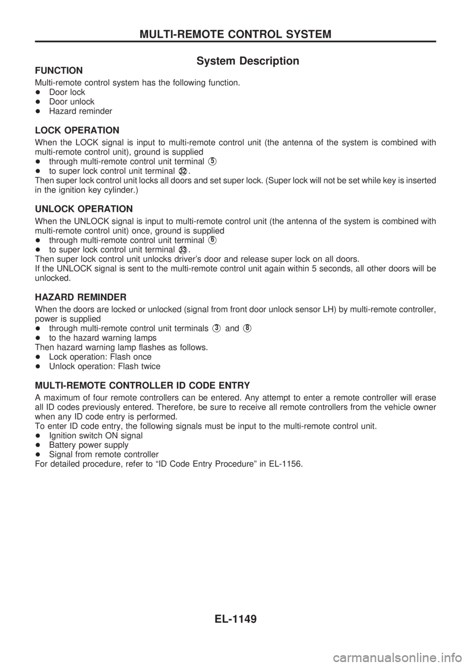
System Description
FUNCTION
Multi-remote control system has the following function.
+Door lock
+Door unlock
+Hazard reminder
LOCK OPERATION
When the LOCK signal is input to multi-remote control unit (the antenna of the system is combined with
multi-remote control unit), ground is supplied
+through multi-remote control unit terminal
V5
+to super lock control unit terminalV32.
Then super lock control unit locks all doors and set super lock. (Super lock will not be set while key is inserted
in the ignition key cylinder.)
UNLOCK OPERATION
When the UNLOCK signal is input to multi-remote control unit (the antenna of the system is combined with
multi-remote control unit) once, ground is supplied
+through multi-remote control unit terminal
V6
+to super lock control unit terminalV33.
Then super lock control unit unlocks driver's door and release super lock on all doors.
If the UNLOCK signal is sent to the multi-remote control unit again within 5 seconds, all other doors will be
unlocked.
HAZARD REMINDER
When the doors are locked or unlocked (signal from front door unlock sensor LH) by multi-remote controller,
power is supplied
+through multi-remote control unit terminals
V3andV8
+to the hazard warning lamps
Then hazard warning lamp flashes as follows.
+Lock operation: Flash once
+Unlock operation: Flash twice
MULTI-REMOTE CONTROLLER ID CODE ENTRY
A maximum of four remote controllers can be entered. Any attempt to enter a remote controller will erase
all ID codes previously entered. Therefore, be sure to receive all remote controllers from the vehicle owner
when any ID code entry is performed.
To enter ID code entry, the following signals must be input to the multi-remote control unit.
+Ignition switch ON signal
+Battery power supply
+Signal from remote controller
For detailed procedure, refer to ªID Code Entry Procedureº in EL-1156.
MULTI-REMOTE CONTROL SYSTEM
EL-1149
![NISSAN PATROL 2000 Electronic Repair Manual DIAGNOSTIC PROCEDURE 5
[Super lock actuator (in door lock actuator assembly)
check]
CHECK OUTPUT SIGNAL FOR SUPER
LOCK ACTUATOR.
Check voltage for super lock actuator.
Put the system in set condition](/manual-img/5/57367/w960_57367-654.png "NISSAN PATROL 2000 Electronic Repair Manual DIAGNOSTIC PROCEDURE 5
[Super lock actuator (in door lock actuator assembly)
check]
CHECK OUTPUT SIGNAL FOR SUPER
LOCK ACTUATOR.
Check voltage for super lock actuator.
Put the system in set condition")