2000 NISSAN PATROL SOLENOID
[x] Cancel search: SOLENOIDPage 38 of 1033
Introduction
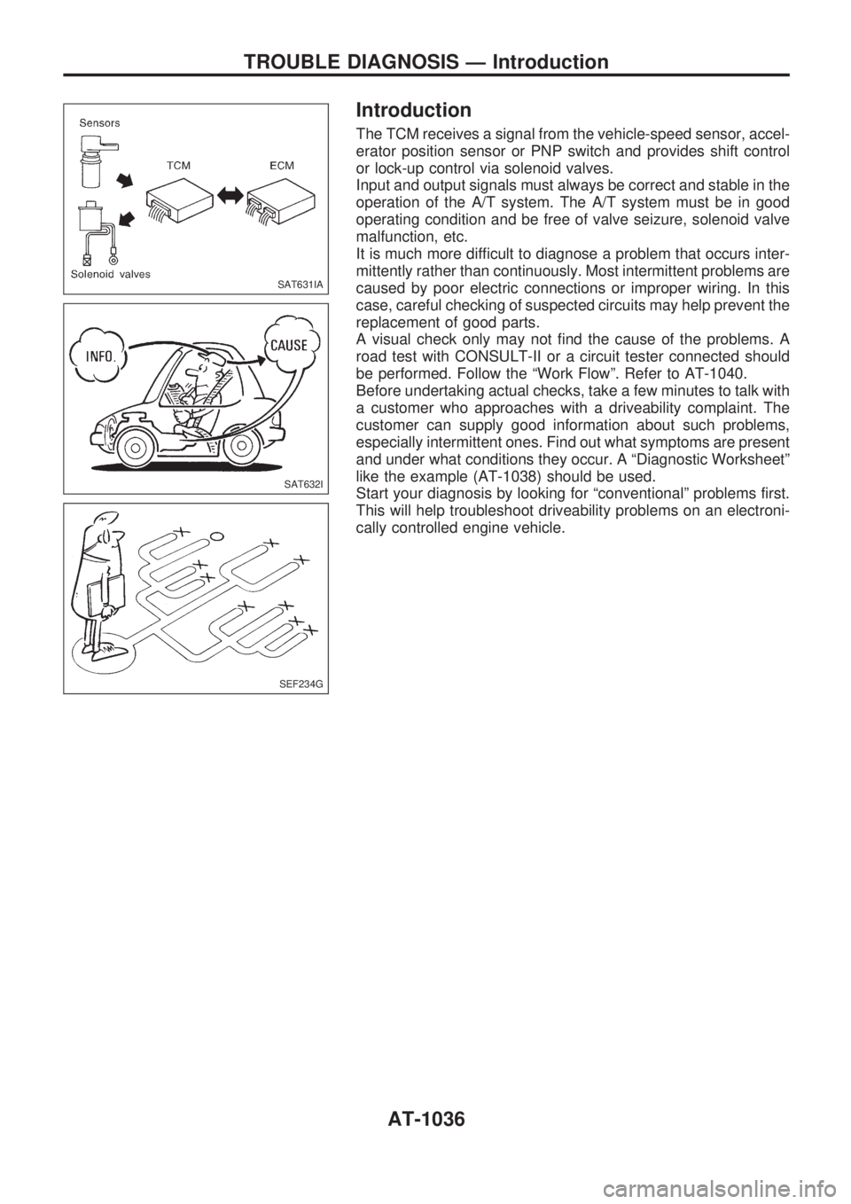
The TCM receives a signal from the vehicle-speed sensor, accel-
erator position sensor or PNP switch and provides shift control
or lock-up control via solenoid valves.
Input and output signals must always be correct and stable in the
operation of the A/T system. The A/T system must be in good
operating condition and be free of valve seizure, solenoid valve
malfunction, etc.
It is much more difficult to diagnose a problem that occurs inter-
mittently rather than continuously. Most intermittent problems are
caused by poor electric connections or improper wiring. In this
case, careful checking of suspected circuits may help prevent the
replacement of good parts.
A visual check only may not find the cause of the problems. A
road test with CONSULT-II or a circuit tester connected should
be performed. Follow the ªWork Flowº. Refer to AT-1040.
Before undertaking actual checks, take a few minutes to talk with
a customer who approaches with a driveability complaint. The
customer can supply good information about such problems,
especially intermittent ones. Find out what symptoms are present
and under what conditions they occur. A ªDiagnostic Worksheetº
like the example (AT-1038) should be used.
Start your diagnosis by looking for ªconventionalº problems first.
This will help troubleshoot driveability problems on an electroni-
cally controlled engine vehicle.
SAT631IA
SAT632I
SEF234G
TROUBLE DIAGNOSIS Ð Introduction
AT-1036
Page 40 of 1033
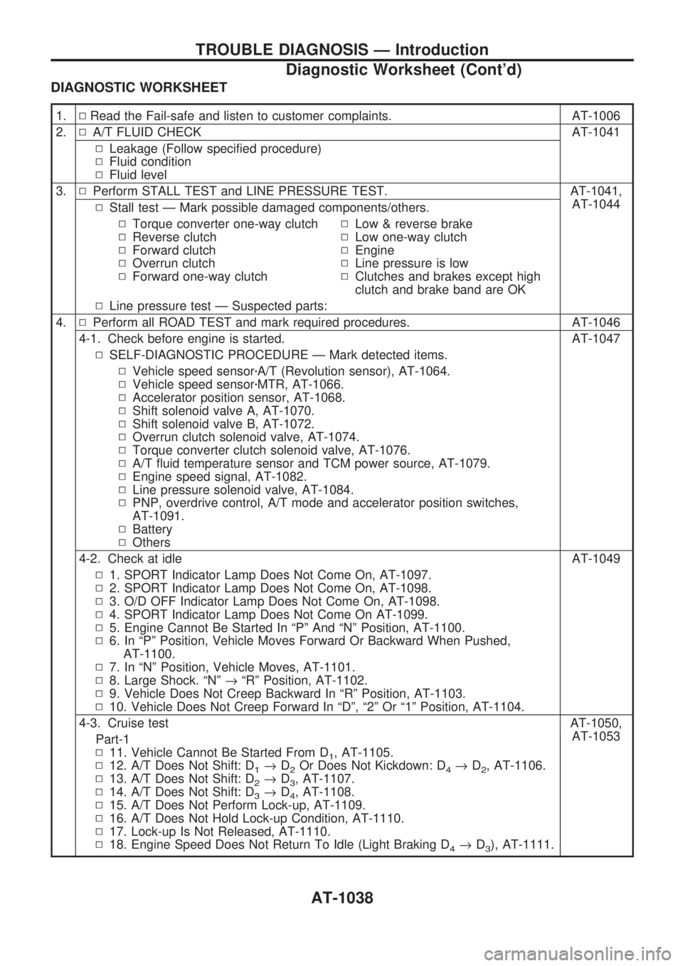
DIAGNOSTIC WORKSHEET
1.NRead the Fail-safe and listen to customer complaints. AT-1006
2.NA/T FLUID CHECK AT-1041
NLeakage (Follow specified procedure)
NFluid condition
NFluid level
3.NPerform STALL TEST and LINE PRESSURE TEST. AT-1041,
AT-1044
NStall test Ð Mark possible damaged components/others.
NTorque converter one-way clutch
NReverse clutch
NForward clutch
NOverrun clutch
NForward one-way clutchNLow & reverse brake
NLow one-way clutch
NEngine
NLine pressure is low
NClutches and brakes except high
clutch and brake band are OK
NLine pressure test Ð Suspected parts:
4.NPerform all ROAD TEST and mark required procedures. AT-1046
4-1. Check before engine is started. AT-1047
NSELF-DIAGNOSTIC PROCEDURE Ð Mark detected items.
NVehicle speed sensorzA/T (Revolution sensor), AT-1064.
NVehicle speed sensorzMTR, AT-1066.
NAccelerator position sensor, AT-1068.
NShift solenoid valve A, AT-1070.
NShift solenoid valve B, AT-1072.
NOverrun clutch solenoid valve, AT-1074.
NTorque converter clutch solenoid valve, AT-1076.
NA/T fluid temperature sensor and TCM power source, AT-1079.
NEngine speed signal, AT-1082.
NLine pressure solenoid valve, AT-1084.
NPNP, overdrive control, A/T mode and accelerator position switches,
AT-1091.
NBattery
NOthers
4-2. Check at idle AT-1049
N1. SPORT Indicator Lamp Does Not Come On, AT-1097.
N2. SPORT Indicator Lamp Does Not Come On, AT-1098.
N3. O/D OFF Indicator Lamp Does Not Come On, AT-1098.
N4. SPORT Indicator Lamp Does Not Come On AT-1099.
N5. Engine Cannot Be Started In ªPº And ªNº Position, AT-1100.
N6. In ªPº Position, Vehicle Moves Forward Or Backward When Pushed,
AT-1100.
N7. In ªNº Position, Vehicle Moves, AT-1101.
N8. Large Shock. ªNº®ªRº Position, AT-1102.
N9. Vehicle Does Not Creep Backward In ªRº Position, AT-1103.
N10. Vehicle Does Not Creep Forward In ªDº, ª2º Or ª1º Position, AT-1104.
4-3. Cruise test AT-1050,
AT-1053
Part-1
N11. Vehicle Cannot Be Started From D
1, AT-1105.
N12. A/T Does Not Shift: D
1®D2Or Does Not Kickdown: D4®D2, AT-1106.
N13. A/T Does Not Shift: D
2®D3, AT-1107.
N14. A/T Does Not Shift: D
3®D4, AT-1108.
N15. A/T Does Not Perform Lock-up, AT-1109.
N16. A/T Does Not Hold Lock-up Condition, AT-1110.
N17. Lock-up Is Not Released, AT-1110.
N18. Engine Speed Does Not Return To Idle (Light Braking D
4®D3), AT-1111.
TROUBLE DIAGNOSIS Ð Introduction
Diagnostic Worksheet (Cont'd)
AT-1038
Page 41 of 1033
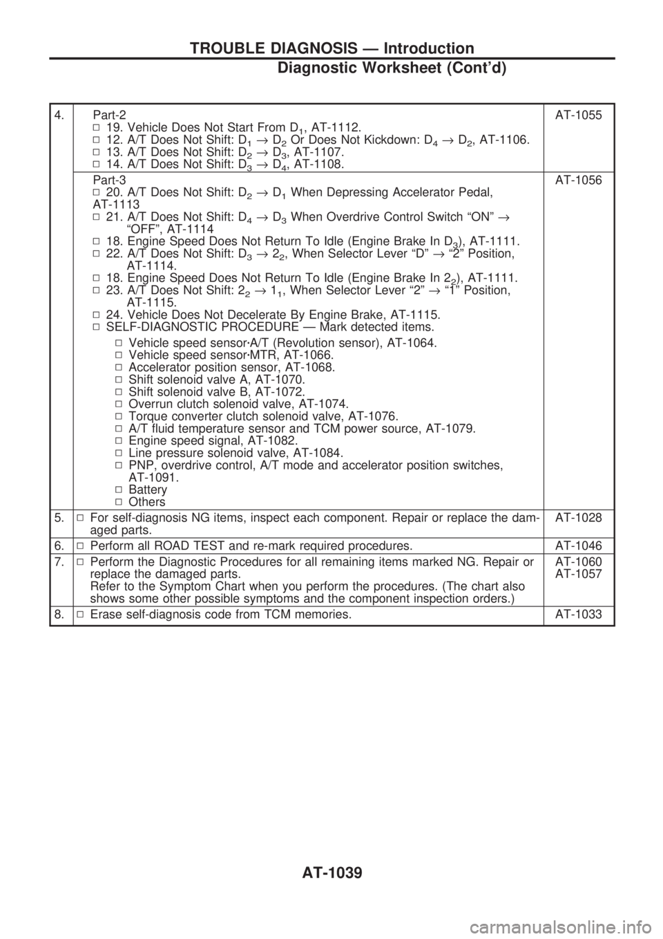
4. Part-2
N19. Vehicle Does Not Start From D
1, AT-1112.
N12. A/T Does Not Shift: D
1®D2Or Does Not Kickdown: D4®D2, AT-1106.
N13. A/T Does Not Shift: D
2®D3, AT-1107.
N14. A/T Does Not Shift: D
3®D4, AT-1108.AT-1055
Part-3
N20. A/T Does Not Shift: D
2®D1When Depressing Accelerator Pedal,
AT-1113
N21. A/T Does Not Shift: D
4®D3When Overdrive Control Switch ªONº®
ªOFFº, AT-1114
N18. Engine Speed Does Not Return To Idle (Engine Brake In D
3), AT-1111.
N22. A/T Does Not Shift: D
3®22, When Selector Lever ªDº®ª2º Position,
AT-1114.
N18. Engine Speed Does Not Return To Idle (Engine Brake In 2
2), AT-1111.
N23. A/T Does Not Shift: 2
2®11, When Selector Lever ª2º®ª1º Position,
AT-1115.
N24. Vehicle Does Not Decelerate By Engine Brake, AT-1115.
NSELF-DIAGNOSTIC PROCEDURE Ð Mark detected items.AT-1056
NVehicle speed sensorzA/T (Revolution sensor), AT-1064.
NVehicle speed sensorzMTR, AT-1066.
NAccelerator position sensor, AT-1068.
NShift solenoid valve A, AT-1070.
NShift solenoid valve B, AT-1072.
NOverrun clutch solenoid valve, AT-1074.
NTorque converter clutch solenoid valve, AT-1076.
NA/T fluid temperature sensor and TCM power source, AT-1079.
NEngine speed signal, AT-1082.
NLine pressure solenoid valve, AT-1084.
NPNP, overdrive control, A/T mode and accelerator position switches,
AT-1091.
NBattery
NOthers
5.NFor self-diagnosis NG items, inspect each component. Repair or replace the dam-
aged parts.AT-1028
6.NPerform all ROAD TEST and re-mark required procedures. AT-1046
7.NPerform the Diagnostic Procedures for all remaining items marked NG. Repair or
replace the damaged parts.
Refer to the Symptom Chart when you perform the procedures. (The chart also
shows some other possible symptoms and the component inspection orders.)AT-1060
AT-1057
8.NErase self-diagnosis code from TCM memories. AT-1033
TROUBLE DIAGNOSIS Ð Introduction
Diagnostic Worksheet (Cont'd)
AT-1039
Page 47 of 1033
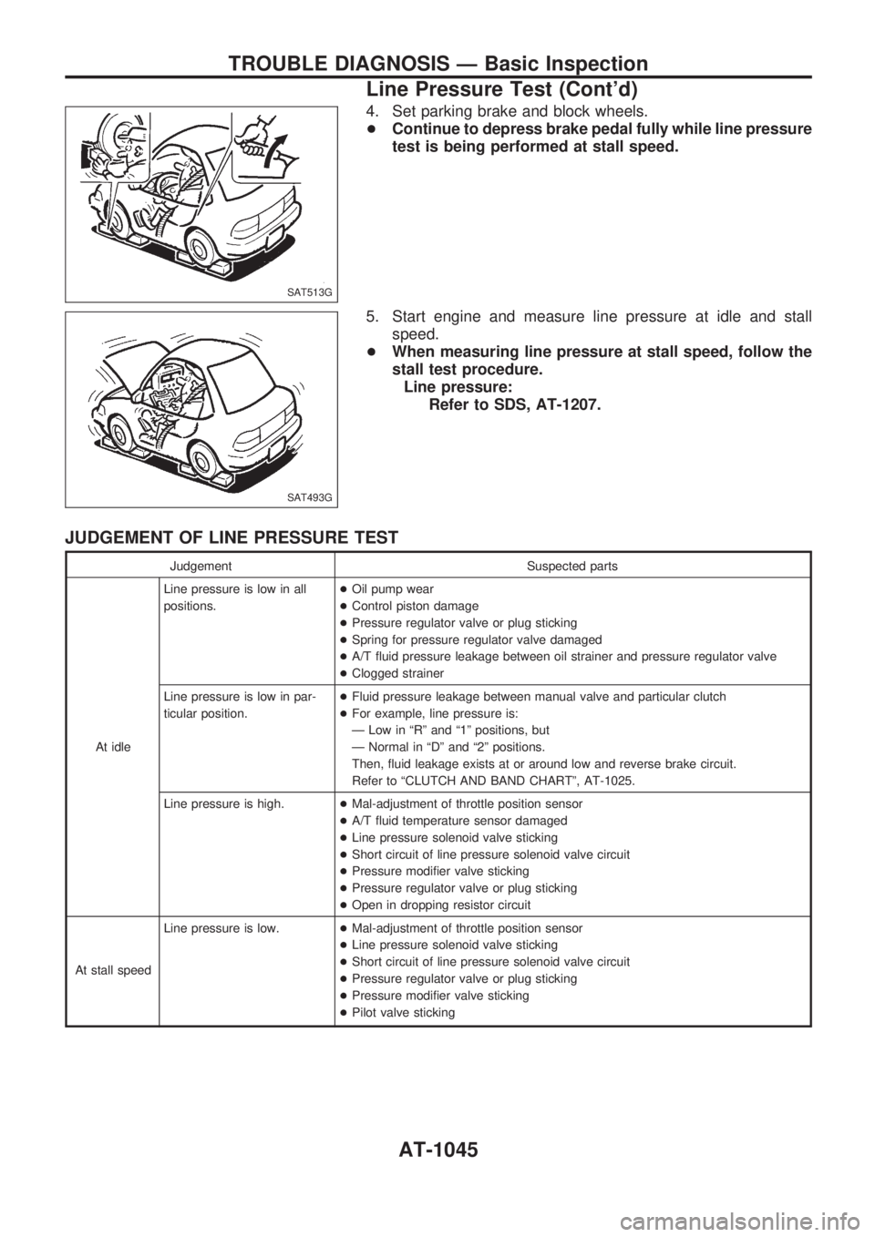
4. Set parking brake and block wheels.
+Continue to depress brake pedal fully while line pressure
test is being performed at stall speed.
5. Start engine and measure line pressure at idle and stall
speed.
+When measuring line pressure at stall speed, follow the
stall test procedure.
Line pressure:
Refer to SDS, AT-1207.
JUDGEMENT OF LINE PRESSURE TEST
Judgement Suspected parts
At idleLine pressure is low in all
positions.+Oil pump wear
+Control piston damage
+Pressure regulator valve or plug sticking
+Spring for pressure regulator valve damaged
+A/T fluid pressure leakage between oil strainer and pressure regulator valve
+Clogged strainer
Line pressure is low in par-
ticular position.+Fluid pressure leakage between manual valve and particular clutch
+For example, line pressure is:
Ð Low in ªRº and ª1º positions, but
Ð Normal in ªDº and ª2º positions.
Then, fluid leakage exists at or around low and reverse brake circuit.
Refer to ªCLUTCH AND BAND CHARTº, AT-1025.
Line pressure is high.+Mal-adjustment of throttle position sensor
+A/T fluid temperature sensor damaged
+Line pressure solenoid valve sticking
+Short circuit of line pressure solenoid valve circuit
+Pressure modifier valve sticking
+Pressure regulator valve or plug sticking
+Open in dropping resistor circuit
At stall speedLine pressure is low.+Mal-adjustment of throttle position sensor
+Line pressure solenoid valve sticking
+Short circuit of line pressure solenoid valve circuit
+Pressure regulator valve or plug sticking
+Pressure modifier valve sticking
+Pilot valve sticking
SAT513G
SAT493G
TROUBLE DIAGNOSIS Ð Basic Inspection
Line Pressure Test (Cont'd)
AT-1045
Page 59 of 1033
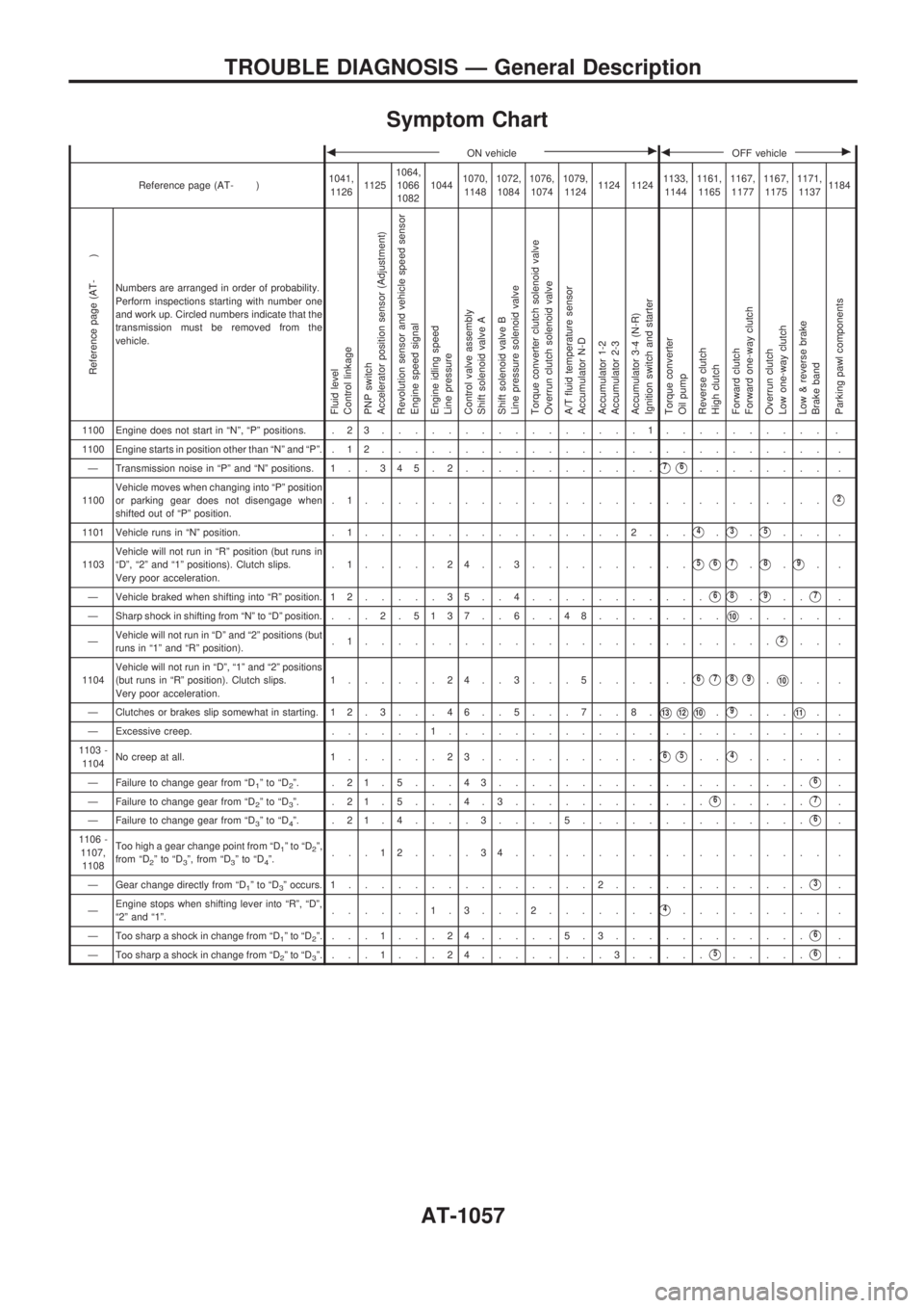
Symptom Chart
bON vehiclecbOFF vehiclec
Reference page (AT- )1041,
112611251064,
1066
108210441070,
11481072,
10841076,
10741079,
11241124 11241133,
11441161,
11651167,
11771167,
11751171,
11371184
Reference page (AT- )
Numbers are arranged in order of probability.
Perform inspections starting with number one
and work up. Circled numbers indicate that the
transmission must be removed from the
vehicle.
Fluid level
Control linkage
PNP switch
Accelerator position sensor (Adjustment)
Revolution sensor and vehicle speed sensor
Engine speed signal
Engine idling speed
Line pressure
Control valve assembly
Shift solenoid valve A
Shift solenoid valve B
Line pressure solenoid valve
Torque converter clutch solenoid valve
Overrun clutch solenoid valve
A/T fluid temperature sensor
Accumulator N-D
Accumulator 1-2
Accumulator 2-3
Accumulator 3-4 (N-R)
Ignition switch and starter
Torque converter
Oil pump
Reverse clutch
High clutch
Forward clutch
Forward one-way clutch
Overrun clutch
Low one-way clutch
Low & reverse brake
Brake band
Parking pawl components
1100 Engine does not start in ªNº, ªPº positions. . 2 3................1.......... .
1100 Engine starts in position other than ªNº and ªPº. . 1 2........................... .
Ð Transmission noise in ªPº and ªNº positions. 1 . . 3 45.2............
V7V6........ .
1100Vehicle moves when changing into ªPº position
or parking gear does not disengage when
shifted out of ªPº position..1............................
V2
1101 Vehicle runs in ªNº position. . 1................2...V4.V3.V5... .
1103Vehicle will not run in ªRº position (but runs in
ªDº, ª2º and ª1º positions). Clutch slips.
Very poor acceleration..1.....24..3..........
V5V6V7.V8.V9..
Ð Vehicle braked when shifting into ªRº position. 1 2.....35..4...........
V6V8.V9..V7.
Ð Sharp shock in shifting from ªNº to ªDº position. . .. 2 . 5137 . . 6 . . 48........
V10..... .
ÐVehicle will not run in ªDº and ª2º positions (but
runs in ª1º and ªRº position)..1.........................
V2.. .
1104Vehicle will not run in ªDº, ª1º and ª2º positions
(but runs in ªRº position). Clutch slips.
Very poor acceleration.1......24..3...5......
V6V7V8V9.V10.. .
Ð Clutches or brakes slip somewhat in starting. 12.3. . .46. .5. . .7. .8.
V13V12V10.V9...V11..
Ð Excessive creep.......1....................... .
1103 -
1104No creep at all. 1......23...........
V6V5..V4..... .
Ð Failure to change gear from ªD
1ºtoªD2º. .21.5...43...................V6.
Ð Failure to change gear from ªD
2ºtoªD3º. .21.5. . .4.3............V6.....V7.
Ð Failure to change gear from ªD
3ºtoªD4º. .21.4....3....5..............V6.
1106 -
1107,
1108Too high a gear change point from ªD
1ºtoªD2º,
from ªD2ºtoªD3º, from ªD3ºtoªD4º....12....34................... .
Ð Gear change directly from ªD
1ºtoªD3º occurs. 1...............2............V3.
ÐEngine stops when shifting lever into ªRº, ªDº,
ª2º and ª1º.......1.3. . .2.......
V4......... .
Ð Too sharp a shock in change from ªD
1ºtoªD2º....1...24.....5.3............V6.
Ð Too sharp a shock in change from ªD
2ºtoªD3º....1...24........3.....V5.....V6.
TROUBLE DIAGNOSIS Ð General Description
AT-1057
Page 60 of 1033
bON vehiclecbOFF vehiclec
Reference page (AT- )1041,
112611251064,
1066
108210441070,
11481072,
10841076,
10741079,
11241124 11241133,
11441161,
11651167,
11771167,
11751171,
11371184
Reference page (AT- )
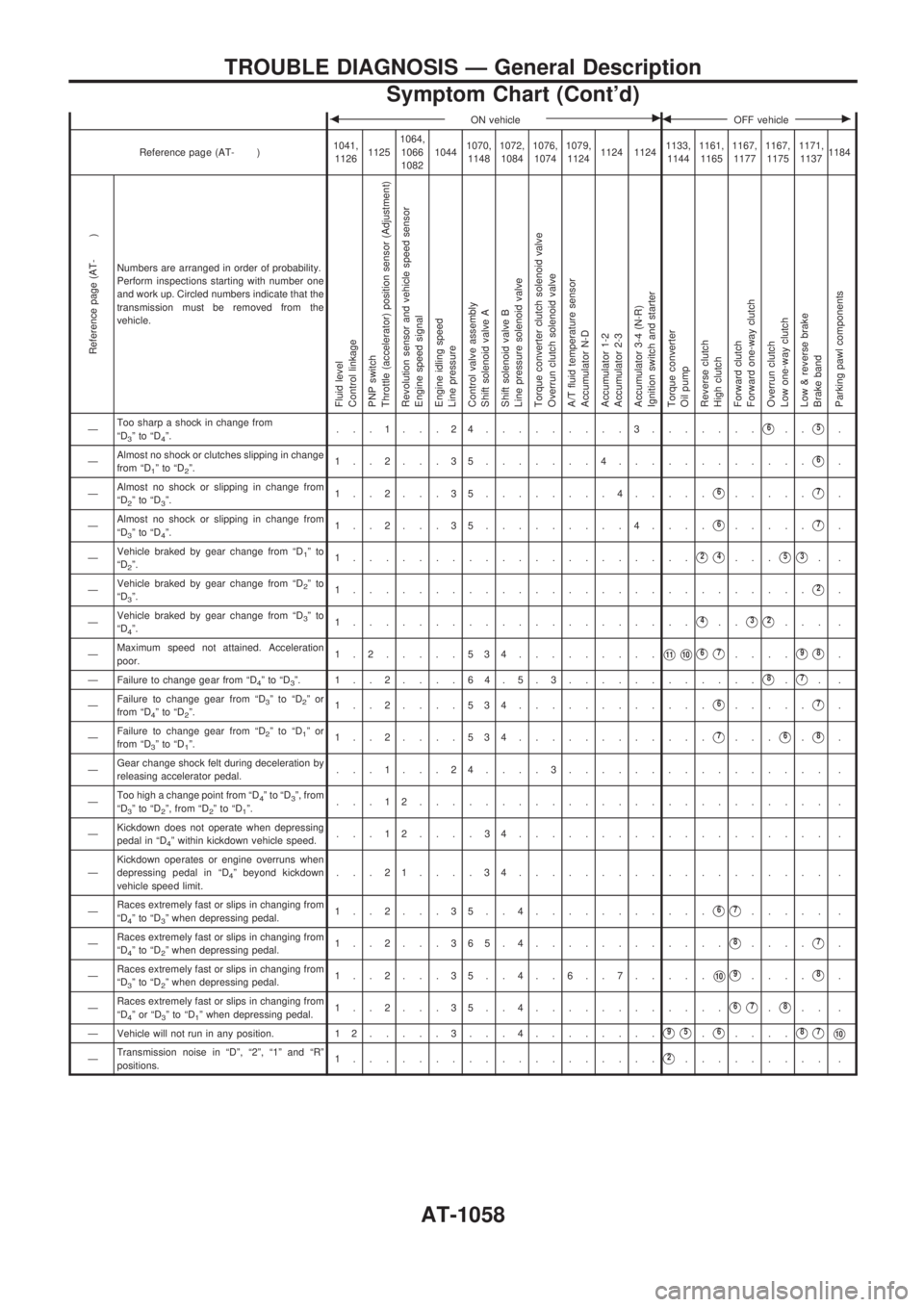
Numbers are arranged in order of probability.
Perform inspections starting with number one
and work up. Circled numbers indicate that the
transmission must be removed from the
vehicle.
Fluid level
Control linkage
PNP switch
Throttle (accelerator) position sensor (Adjustment)
Revolution sensor and vehicle speed sensor
Engine speed signal
Engine idling speed
Line pressure
Control valve assembly
Shift solenoid valve A
Shift solenoid valve B
Line pressure solenoid valve
Torque converter clutch solenoid valve
Overrun clutch solenoid valve
A/T fluid temperature sensor
Accumulator N-D
Accumulator 1-2
Accumulator 2-3
Accumulator 3-4 (N-R)
Ignition switch and starter
Torque converter
Oil pump
Reverse clutch
High clutch
Forward clutch
Forward one-way clutch
Overrun clutch
Low one-way clutch
Low & reverse brake
Brake band
Parking pawl components
ÐToo sharp a shock in change from
ªD3ºtoªD4º....1...24.........3.......V6..V5.
ÐAlmost no shock or clutches slipping in change
from ªD
1ºtoªD2º.1..2...35.......4............V6.
ÐAlmost no shock or slipping in change from
ªD
2ºtoªD3º.1..2...35........4.....V6.....V7.
ÐAlmost no shock or slipping in change from
ªD
3ºtoªD4º.1..2...35.........4....V6.....V7.
ÐVehicle braked by gear change from ªD
1ºto
ªD2º.1.....................V2V4...V5V3..
ÐVehicle braked by gear change from ªD
2ºto
ªD3º.1............................V2.
ÐVehicle braked by gear change from ªD
3ºto
ªD4º.1.....................V4..V3V2... .
ÐMaximum speed not attained. Acceleration
poor.1.2.....534.........
V11V10V6V7....V9V8.
Ð Failure to change gear from ªD
4ºtoªD3º. 1..2....64.5.3............V8.V7..
ÐFailure to change gear from ªD
3ºtoªD2ºor
from ªD4ºtoªD2º.1..2....534............V6.....V7.
ÐFailure to change gear from ªD
2ºtoªD1ºor
from ªD3ºtoªD1º.1..2....534............V7...V6.V8.
ÐGear change shock felt during deceleration by
releasing accelerator pedal....1...24....3................ .
ÐToo high a change point from ªD
4ºtoªD3º, from
ªD3ºtoªD2º, from ªD2ºtoªD1º....12......................... .
ÐKickdown does not operate when depressing
pedal in ªD
4º within kickdown vehicle speed....12....34................... .
ÐKickdown operates or engine overruns when
depressing pedal in ªD
4º beyond kickdown
vehicle speed limit....21....34................... .
ÐRaces extremely fast or slips in changing from
ªD
4ºtoªD3º when depressing pedal.1..2...35..4...........V6V7..... .
ÐRaces extremely fast or slips in changing from
ªD
4ºtoªD2º when depressing pedal.1..2...365.4............V8....V7.
ÐRaces extremely fast or slips in changing from
ªD
3ºtoªD2º when depressing pedal.1..2...35..4..6..7.....V10V9....V8.
ÐRaces extremely fast or slips in changing from
ªD
4ºorªD3ºtoªD1º when depressing pedal.1..2...35..4............V6V7.V8.. .
Ð Vehicle will not run in any position. 1 2.....3...4........
V9V5.V6....V8V7V10
ÐTransmission noise in ªDº, ª2º, ª1º and ªRº
positions.1...................V2......... .
TROUBLE DIAGNOSIS Ð General Description
Symptom Chart (Cont'd)
AT-1058
Page 61 of 1033
bON vehiclecbOFF vehiclec
Reference page (AT- )1041,
112611251064,
1066
108210441070,
11481072,
10841076,
10741079,
11241124 11241133,
11441161,
11651167,
11771167,
11751171,
11371184
Reference page (AT- )
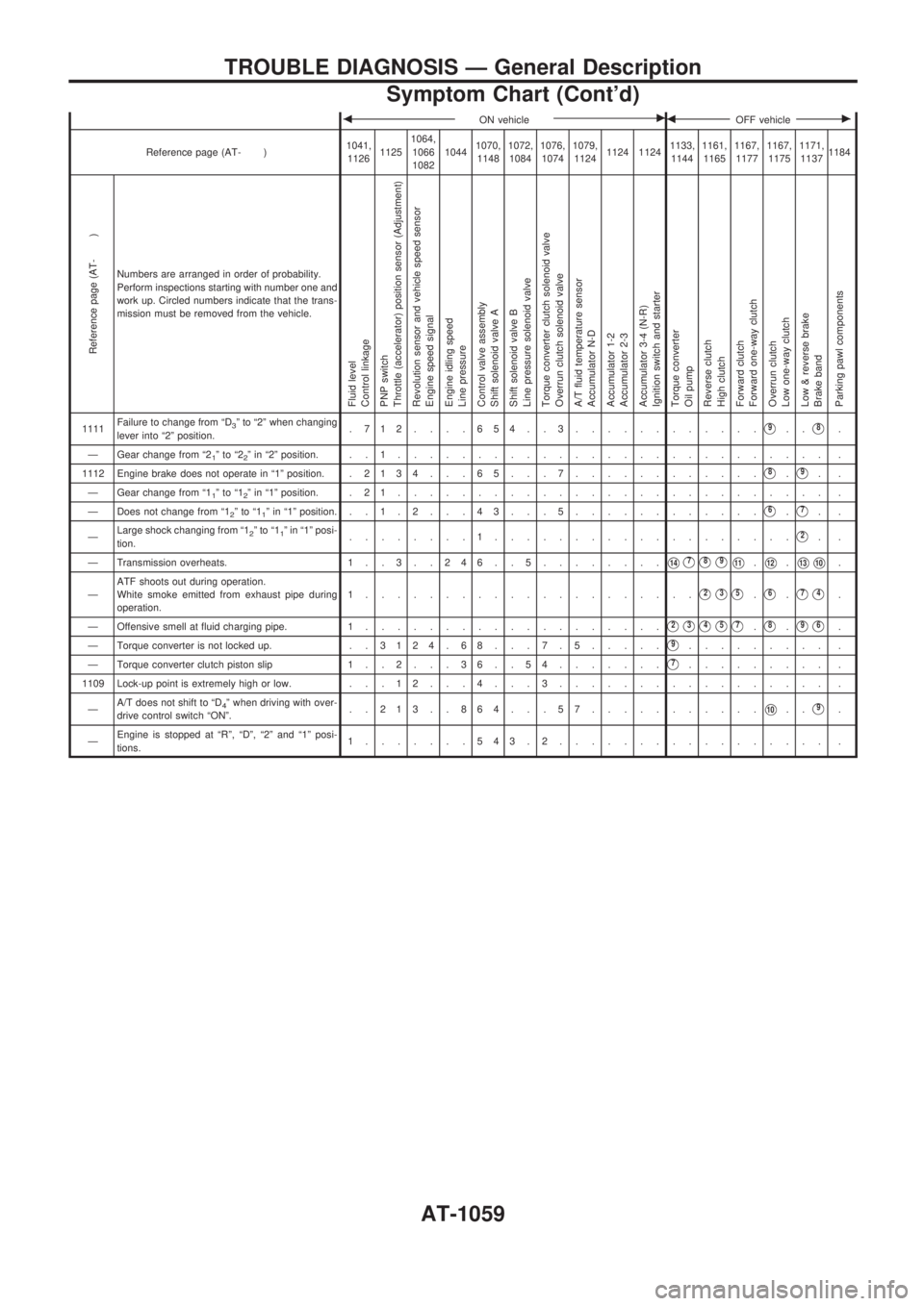
Numbers are arranged in order of probability.
Perform inspections starting with number one and
work up. Circled numbers indicate that the trans-
mission must be removed from the vehicle.
Fluid level
Control linkage
PNP switch
Throttle (accelerator) position sensor (Adjustment)
Revolution sensor and vehicle speed sensor
Engine speed signal
Engine idling speed
Line pressure
Control valve assembly
Shift solenoid valve A
Shift solenoid valve B
Line pressure solenoid valve
Torque converter clutch solenoid valve
Overrun clutch solenoid valve
A/T fluid temperature sensor
Accumulator N-D
Accumulator 1-2
Accumulator 2-3
Accumulator 3-4 (N-R)
Ignition switch and starter
Torque converter
Oil pump
Reverse clutch
High clutch
Forward clutch
Forward one-way clutch
Overrun clutch
Low one-way clutch
Low & reverse brake
Brake band
Parking pawl components
1111Failure to change from ªD3º to ª2º when changing
lever into ª2º position..712....654..3............V9..V8.
Ð Gear change from ª2
1ºtoª22º in ª2º position. . . 1........................... .
1112 Engine brake does not operate in ª1º position. .2134 . . . 65 . . . 7............
V8.V9..
Ð Gear change from ª1
1ºtoª12º in ª1º position. . 2 1........................... .
Ð Does not change from ª1
2ºtoª11º in ª1º position. ..1.2. . .43. . .5............V6.V7..
ÐLarge shock changing from ª1
2ºtoª11º in ª1º posi-
tion.........1...................V2..
Ð Transmission overheats. 1 . . 3 . . 2 4 6 . . 5........
V14V7V8V9V11.V12.V13V10.
ÐATF shoots out during operation.
White smoke emitted from exhaust pipe during
operation.1.....................
V2V3V5.V6.V7V4.
Ð Offensive smell at fluid charging pipe. 1...................
V2V3V4V5V7.V8.V9V6.
Ð Torque converter is not locked up. . .3124.68. . .7.5.....
V9......... .
Ð Torque converter clutch piston slip 1 . . 2 . . . 3 6 . . 5 4.......
V7......... .
1109 Lock-up point is extremely high or low. . . . 1 2 . . . 4 . . . 3................. .
ÐA/T does not shift to ªD
4º when driving with over-
drive control switch ªONº...213..864...57...........V10..V9.
ÐEngine is stopped at ªRº, ªDº, ª2º and ª1º posi-
tions.1.......543.2................. .
TROUBLE DIAGNOSIS Ð General Description
Symptom Chart (Cont'd)
AT-1059
Page 62 of 1033
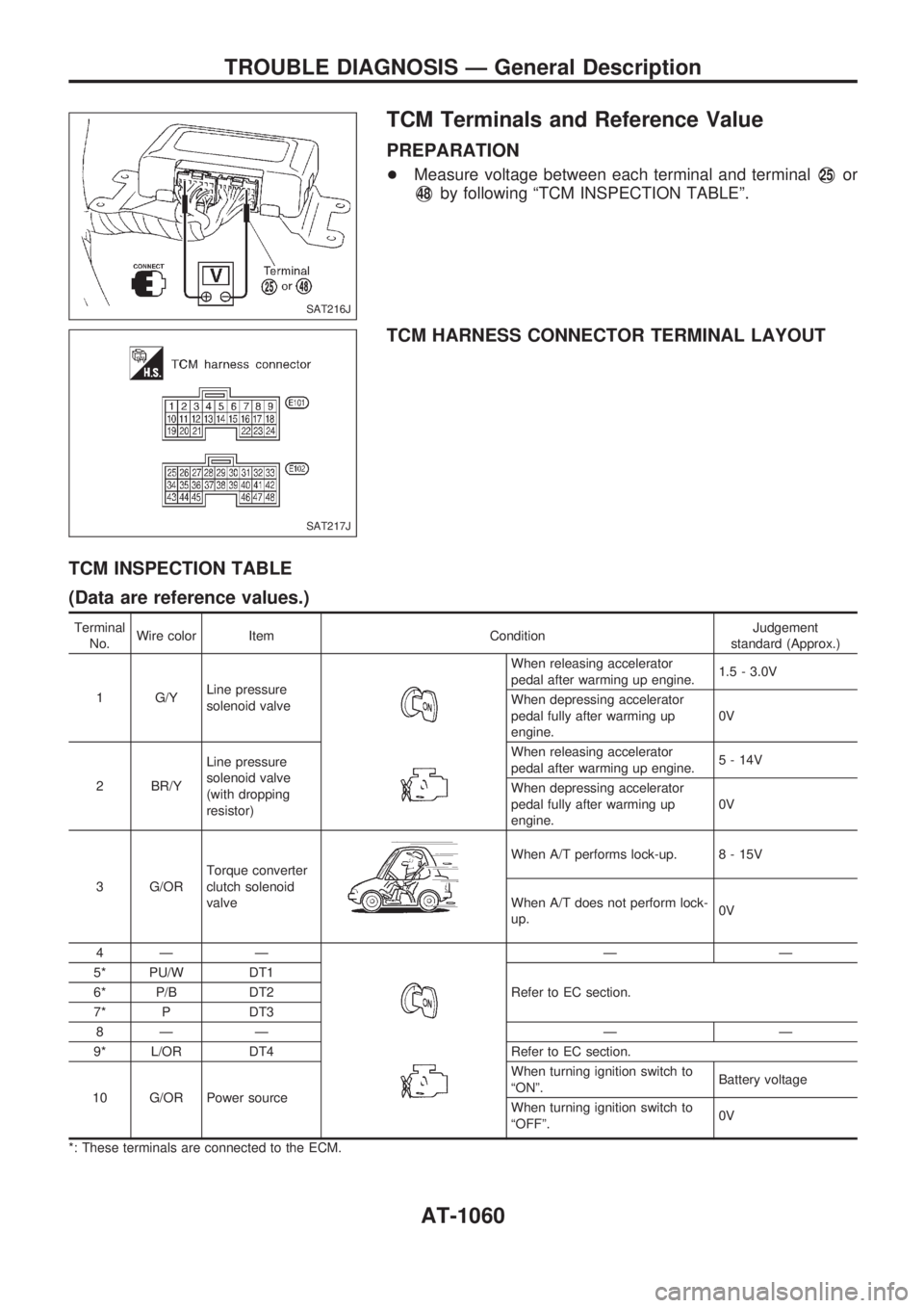
TCM Terminals and Reference Value
PREPARATION
+Measure voltage between each terminal and terminalV25or
V48by following ªTCM INSPECTION TABLEº.
TCM HARNESS CONNECTOR TERMINAL LAYOUT
TCM INSPECTION TABLE
(Data are reference values.)
Terminal
No.Wire color Item ConditionJudgement
standard (Approx.)
1 G/YLine pressure
solenoid valve
When releasing accelerator
pedal after warming up engine.1.5 - 3.0V
When depressing accelerator
pedal fully after warming up
engine.0V
2 BR/YLine pressure
solenoid valve
(with dropping
resistor)When releasing accelerator
pedal after warming up engine.5 - 14V
When depressing accelerator
pedal fully after warming up
engine.0V
3 G/ORTorque converter
clutch solenoid
valve
When A/T performs lock-up. 8 - 15V
When A/T does not perform lock-
up.0V
4Ð Ð
ÐÐ
5* PU/W DT1
Refer to EC section. 6* P/B DT2
7* P DT3
8Ð Ð Ð Ð
9* L/OR DT4 Refer to EC section.
10 G/OR Power sourceWhen turning ignition switch to
ªONº.Battery voltage
When turning ignition switch to
ªOFFº.0V
*: These terminals are connected to the ECM.
SAT216J
SAT217J
TROUBLE DIAGNOSIS Ð General Description
AT-1060