2000 NISSAN PATROL SOLENOID
[x] Cancel search: SOLENOIDPage 63 of 1033
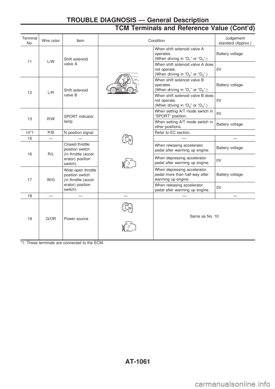
Terminal
No.Wire color Item ConditionJudgement
standard (Approx.)
11 L/WShift solenoid
valve A
When shift solenoid valve A
operates.
(When driving in ªD
1ºorªD4º.)Battery voltage
When shift solenoid valve A does
not operate.
(When driving in ªD
2ºorªD3º.)0V
12 L/RShift solenoid
valve BWhen shift solenoid valve B
operates.
(When driving in ªD
1ºorªD2º.)Battery voltage
When shift solenoid valve B does
not operate.
(When driving in ªD
3ºorªD4º.)0V
13 R/WSPORT indicator
lamp
When setting A/T mode switch in
ªSPORTº position.0V
When setting A/T mode switch in
other positions.Battery voltage
14*1 P/B N position signal Refer to EC section.
15 Ð Ð Ð Ð
16 R/LClosed throttle
position switch
(in throttle (accel-
erator) position
switch)When releasing accelerator
pedal after warming up engine.Battery voltage
When depressing accelerator
pedal after warming up engine.0V
17 W/GWide open throttle
position switch
(in throttle (accel-
erator) position
switch)When depressing accelerator
pedal more than half-way after
warming up engine.Battery voltage
When releasing accelerator
pedal after warming up engine.0V
18 Ð Ð Ð Ð Ð
19 G/OR Power source
Same as No. 10
*1: These terminals are connected to the ECM.
TROUBLE DIAGNOSIS Ð General Description
TCM Terminals and Reference Value (Cont'd)
AT-1061
Page 64 of 1033
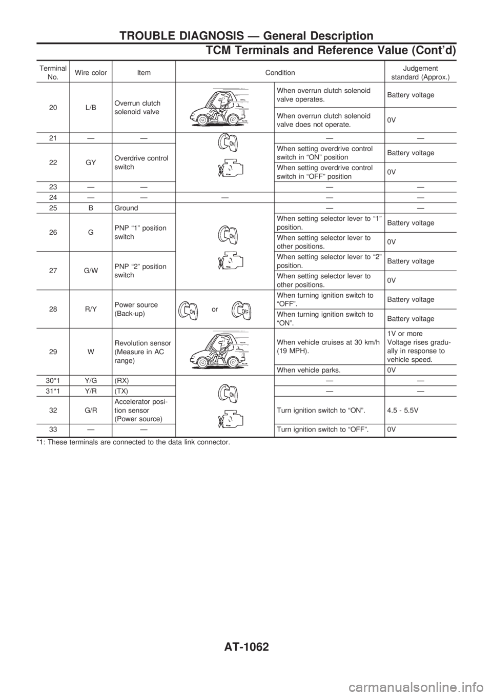
Terminal
No.Wire color Item ConditionJudgement
standard (Approx.)
20 L/BOverrun clutch
solenoid valve
When overrun clutch solenoid
valve operates.Battery voltage
When overrun clutch solenoid
valve does not operate.0V
21 Ð Ð
ÐÐ
22 GYOverdrive control
switchWhen setting overdrive control
switch in ªONº positionBattery voltage
When setting overdrive control
switch in ªOFFº position0V
23 Ð Ð Ð Ð
24 Ð Ð Ð Ð Ð
25 B Ground
ÐÐ
26 GPNP ª1º position
switchWhen setting selector lever to ª1º
position.Battery voltage
When setting selector lever to
other positions.0V
27 G/WPNP ª2º position
switchWhen setting selector lever to ª2º
position.Battery voltage
When setting selector lever to
other positions.0V
28 R/YPower source
(Back-up)
or
When turning ignition switch to
ªOFFº.Battery voltage
When turning ignition switch to
ªONº.Battery voltage
29 WRevolution sensor
(Measure in AC
range)
When vehicle cruises at 30 km/h
(19 MPH).1V or more
Voltage rises gradu-
ally in response to
vehicle speed.
When vehicle parks. 0V
30*1 Y/G (RX)
ÐÐ
31*1 Y/R (TX) Ð Ð
32 G/RAccelerator posi-
tion sensor
(Power source)Turn ignition switch to ªONº. 4.5 - 5.5V
33 Ð Ð Turn ignition switch to ªOFFº. 0V
*1: These terminals are connected to the data link connector.
TROUBLE DIAGNOSIS Ð General Description
TCM Terminals and Reference Value (Cont'd)
AT-1062
Page 72 of 1033
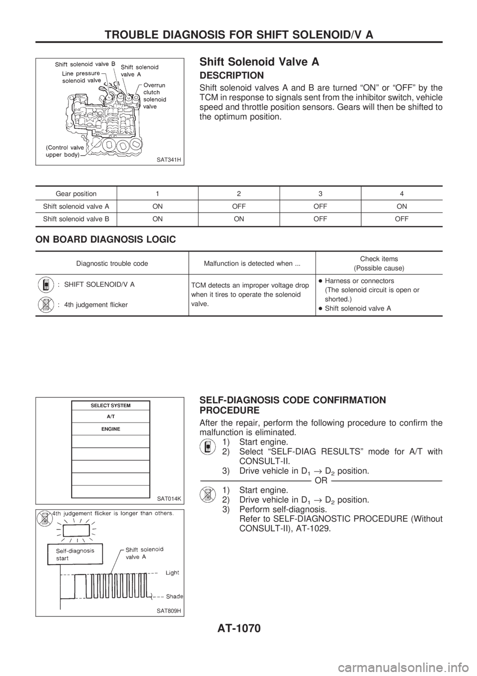
Shift Solenoid Valve A
DESCRIPTION
Shift solenoid valves A and B are turned ªONº or ªOFFº by the
TCM in response to signals sent from the inhibitor switch, vehicle
speed and throttle position sensors. Gears will then be shifted to
the optimum position.
Gear position1234
Shift solenoid valve A ON OFF OFF ON
Shift solenoid valve B ON ON OFF OFF
ON BOARD DIAGNOSIS LOGIC
Diagnostic trouble code Malfunction is detected when ...Check items
(Possible cause)
: SHIFT SOLENOID/V A
TCM detects an improper voltage drop
when it tires to operate the solenoid
valve.+Harness or connectors
(The solenoid circuit is open or
shorted.)
+Shift solenoid valve A
: 4th judgement flicker
SELF-DIAGNOSIS CODE CONFIRMATION
PROCEDURE
After the repair, perform the following procedure to confirm the
malfunction is eliminated.
1) Start engine.
2) Select ªSELF-DIAG RESULTSº mode for A/T with
CONSULT-II.
3) Drive vehicle in D
1®D2position.
-------------------------------------------------------------------------------------------------------------------------------------------------------------------------------------------------------------------------------------------------OR-------------------------------------------------------------------------------------------------------------------------------------------------------------------------------------------------------------------------------------------------
1) Start engine.
2) Drive vehicle in D
1®D2position.
3) Perform self-diagnosis.
Refer to SELF-DIAGNOSTIC PROCEDURE (Without
CONSULT-II), AT-1029.
SAT341H
SAT014K
SAT809H
TROUBLE DIAGNOSIS FOR SHIFT SOLENOID/V A
AT-1070
Page 73 of 1033
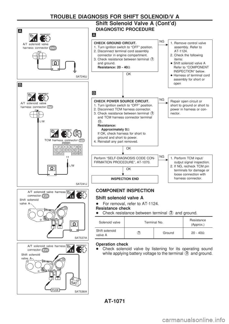
DIAGNOSTIC PROCEDURE
CHECK GROUND CIRCUIT.
1. Turn ignition switch to ªOFFº position.
2. Disconnect terminal cord assembly
connector in engine compartment.
3. Check resistance between terminal
V3
and ground.
Resistance: 20 - 40W
OK
cNG
1. Remove control valve
assembly. Refer to
AT-1124.
2. Check the following
items:
+Shift solenoid valve A
Refer to ªCOMPONENT
INSPECTIONº below.
+Harness of terminal cord
assembly for short or
open
CHECK POWER SOURCE CIRCUIT.
1. Turn ignition switch to ªOFFº position.
2. Disconnect TCM harness connector.
3. Check resistance between terminal
V3
and TCM harness connector terminal
V11.
Resistance:
Approximately 0W
If OK, check harness for short to
ground and short to power.
4. Reinstall any part removed.
OK
cNG
Repair open circuit or
short to ground or short to
power in harness or con-
nector.
Perform ªSELF-DIAGNOSIS CODE CON-
FIRMATION PROCEDUREº, AT-1070.
OK
cNG
1. Perform TCM input/
output signal inspection.
2. If NG, recheck TCM pin
terminals for damage or
loose connection with
harness connector.
INSPECTION END
COMPONENT INSPECTION
Shift solenoid valve A
+For removal, refer to AT-1124.
Resistance check
+Check resistance between terminal
V3and ground.
Solenoid valve Terminal No.Resistance
(Approx.)
Shift solenoid
valve A
V3Ground 20 - 40W
Operation check
+Check solenoid valve by listening for its operating sound
while applying battery voltage to the terminal
V3and ground.
SAT240J
SAT241J
SAT537IA
SAT536IA
.
.
.
TROUBLE DIAGNOSIS FOR SHIFT SOLENOID/V A
Shift Solenoid Valve A (Cont'd)
AT-1071
Page 74 of 1033
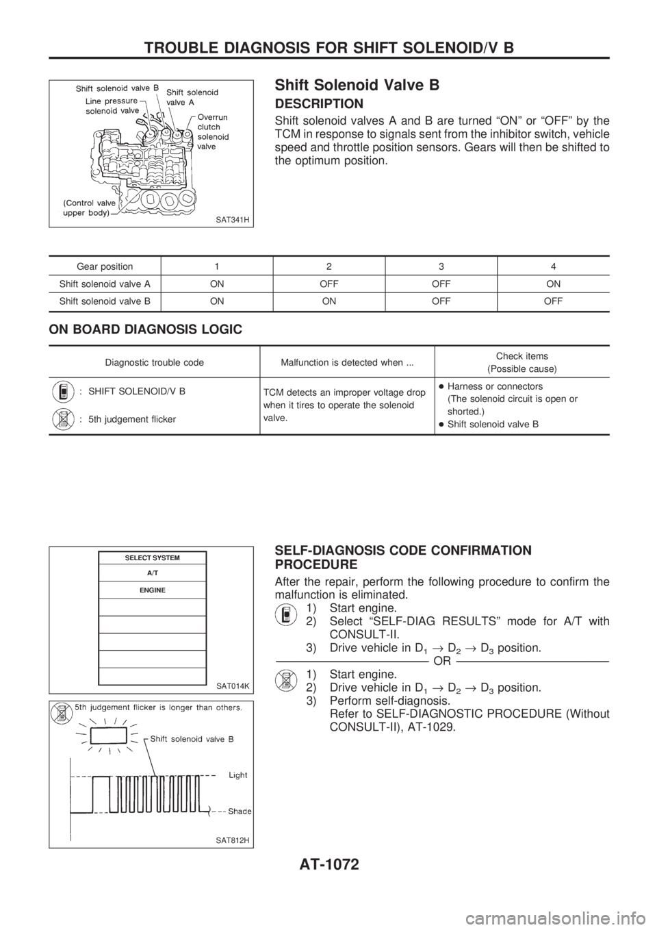
Shift Solenoid Valve B
DESCRIPTION
Shift solenoid valves A and B are turned ªONº or ªOFFº by the
TCM in response to signals sent from the inhibitor switch, vehicle
speed and throttle position sensors. Gears will then be shifted to
the optimum position.
Gear position1234
Shift solenoid valve A ON OFF OFF ON
Shift solenoid valve B ON ON OFF OFF
ON BOARD DIAGNOSIS LOGIC
Diagnostic trouble code Malfunction is detected when ...Check items
(Possible cause)
: SHIFT SOLENOID/V B
TCM detects an improper voltage drop
when it tires to operate the solenoid
valve.+Harness or connectors
(The solenoid circuit is open or
shorted.)
+Shift solenoid valve B
: 5th judgement flicker
SELF-DIAGNOSIS CODE CONFIRMATION
PROCEDURE
After the repair, perform the following procedure to confirm the
malfunction is eliminated.
1) Start engine.
2) Select ªSELF-DIAG RESULTSº mode for A/T with
CONSULT-II.
3) Drive vehicle in D
1®D2®D3position.
-------------------------------------------------------------------------------------------------------------------------------------------------------------------------------------------------------------------------------------------------OR-------------------------------------------------------------------------------------------------------------------------------------------------------------------------------------------------------------------------------------------------
1) Start engine.
2) Drive vehicle in D
1®D2®D3position.
3) Perform self-diagnosis.
Refer to SELF-DIAGNOSTIC PROCEDURE (Without
CONSULT-II), AT-1029.
SAT341H
SAT014K
SAT812H
TROUBLE DIAGNOSIS FOR SHIFT SOLENOID/V B
AT-1072
Page 75 of 1033
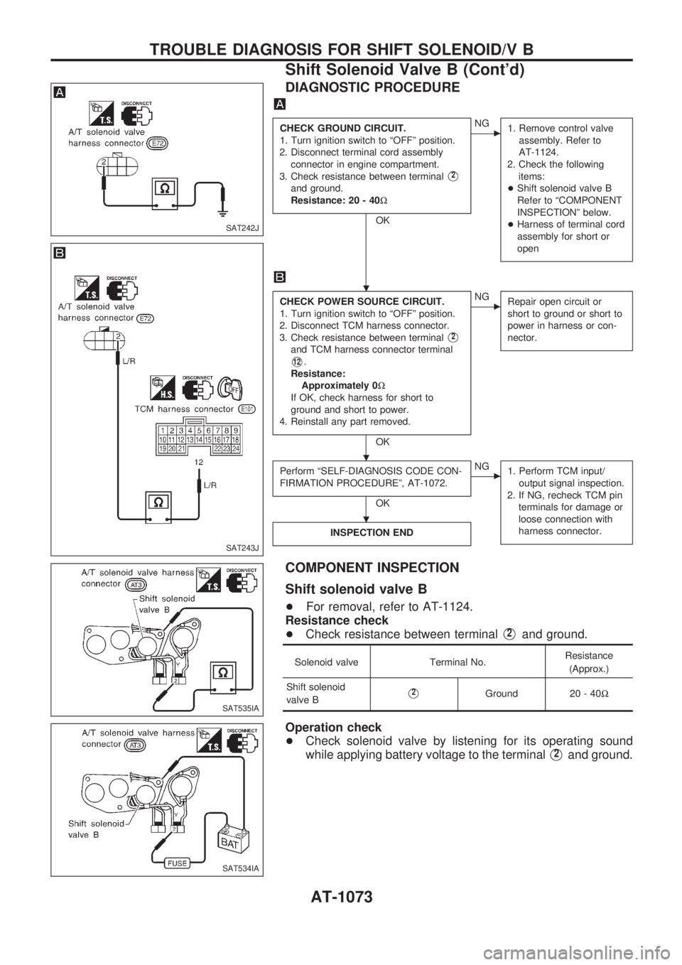
DIAGNOSTIC PROCEDURE
CHECK GROUND CIRCUIT.
1. Turn ignition switch to ªOFFº position.
2. Disconnect terminal cord assembly
connector in engine compartment.
3. Check resistance between terminal
V2
and ground.
Resistance: 20 - 40W
OK
cNG
1. Remove control valve
assembly. Refer to
AT-1124.
2. Check the following
items:
+Shift solenoid valve B
Refer to ªCOMPONENT
INSPECTIONº below.
+Harness of terminal cord
assembly for short or
open
CHECK POWER SOURCE CIRCUIT.
1. Turn ignition switch to ªOFFº position.
2. Disconnect TCM harness connector.
3. Check resistance between terminal
V2
and TCM harness connector terminal
V12.
Resistance:
Approximately 0W
If OK, check harness for short to
ground and short to power.
4. Reinstall any part removed.
OK
cNG
Repair open circuit or
short to ground or short to
power in harness or con-
nector.
Perform ªSELF-DIAGNOSIS CODE CON-
FIRMATION PROCEDUREº, AT-1072.
OK
cNG
1. Perform TCM input/
output signal inspection.
2. If NG, recheck TCM pin
terminals for damage or
loose connection with
harness connector.
INSPECTION END
COMPONENT INSPECTION
Shift solenoid valve B
+For removal, refer to AT-1124.
Resistance check
+Check resistance between terminal
V2and ground.
Solenoid valve Terminal No.Resistance
(Approx.)
Shift solenoid
valve B
V2Ground 20 - 40W
Operation check
+Check solenoid valve by listening for its operating sound
while applying battery voltage to the terminal
V2and ground.
SAT242J
SAT243J
SAT535IA
SAT534IA
.
.
.
TROUBLE DIAGNOSIS FOR SHIFT SOLENOID/V B
Shift Solenoid Valve B (Cont'd)
AT-1073
Page 76 of 1033
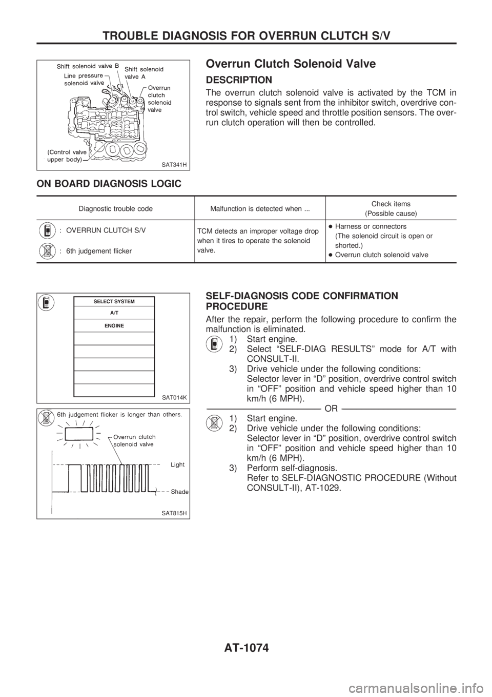
Overrun Clutch Solenoid Valve
DESCRIPTION
The overrun clutch solenoid valve is activated by the TCM in
response to signals sent from the inhibitor switch, overdrive con-
trol switch, vehicle speed and throttle position sensors. The over-
run clutch operation will then be controlled.
ON BOARD DIAGNOSIS LOGIC
Diagnostic trouble code Malfunction is detected when ...Check items
(Possible cause)
: OVERRUN CLUTCH S/V
TCM detects an improper voltage drop
when it tires to operate the solenoid
valve.+Harness or connectors
(The solenoid circuit is open or
shorted.)
+Overrun clutch solenoid valve
: 6th judgement flicker
SELF-DIAGNOSIS CODE CONFIRMATION
PROCEDURE
After the repair, perform the following procedure to confirm the
malfunction is eliminated.
1) Start engine.
2) Select ªSELF-DIAG RESULTSº mode for A/T with
CONSULT-II.
3) Drive vehicle under the following conditions:
Selector lever in ªDº position, overdrive control switch
in ªOFFº position and vehicle speed higher than 10
km/h (6 MPH).
-------------------------------------------------------------------------------------------------------------------------------------------------------------------------------------------------------------------------------------------------OR-------------------------------------------------------------------------------------------------------------------------------------------------------------------------------------------------------------------------------------------------
1) Start engine.
2) Drive vehicle under the following conditions:
Selector lever in ªDº position, overdrive control switch
in ªOFFº position and vehicle speed higher than 10
km/h (6 MPH).
3) Perform self-diagnosis.
Refer to SELF-DIAGNOSTIC PROCEDURE (Without
CONSULT-II), AT-1029.
SAT341H
SAT014K
SAT815H
TROUBLE DIAGNOSIS FOR OVERRUN CLUTCH S/V
AT-1074
Page 77 of 1033
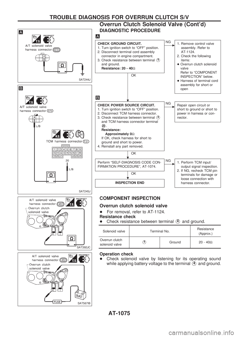
DIAGNOSTIC PROCEDURE
CHECK GROUND CIRCUIT.
1. Turn ignition switch to ªOFFº position.
2. Disconnect terminal cord assembly
connector in engine compartment.
3. Check resistance between terminal
V4
and ground.
Resistance: 20 - 40W
OK
cNG
1. Remove control valve
assembly. Refer to
AT-1124.
2. Check the following
items:
+Overrun clutch solenoid
valve
Refer to ªCOMPONENT
INSPECTIONº below.
+Harness of terminal cord
assembly for short or
open
CHECK POWER SOURCE CIRCUIT.
1. Turn ignition switch to ªOFFº position.
2. Disconnect TCM harness connector.
3. Check resistance between terminal
V4
and TCM harness connector terminal
V20.
Resistance:
Approximately 0W
If OK, check harness for short to
ground and short to power.
4. Reinstall any part removed.
OK
cNG
Repair open circuit or
short to ground or short to
power in harness or con-
nector.
Perform ªSELF-DIAGNOSIS CODE CON-
FIRMATION PROCEDUREº, AT-1074.
OK
cNG
1. Perform TCM input/
output signal inspection.
2. If NG, recheck TCM pin
terminals for damage or
loose connection with
harness connector.
INSPECTION END
COMPONENT INSPECTION
Overrun clutch solenoid valve
+For removal, refer to AT-1124.
Resistance check
+Check resistance between terminal
V4and ground.
Solenoid valve Terminal No.Resistance
(Approx.)
Overrun clutch
solenoid valve
V4Ground 20 - 40W
Operation check
+Check solenoid valve by listening for its operating sound
while applying battery voltage to the terminal
V4and ground.
SAT244J
SAT245J
SAT392JC
SAT567IB
.
.
.
TROUBLE DIAGNOSIS FOR OVERRUN CLUTCH S/V
Overrun Clutch Solenoid Valve (Cont'd)
AT-1075