Page 115 of 1033
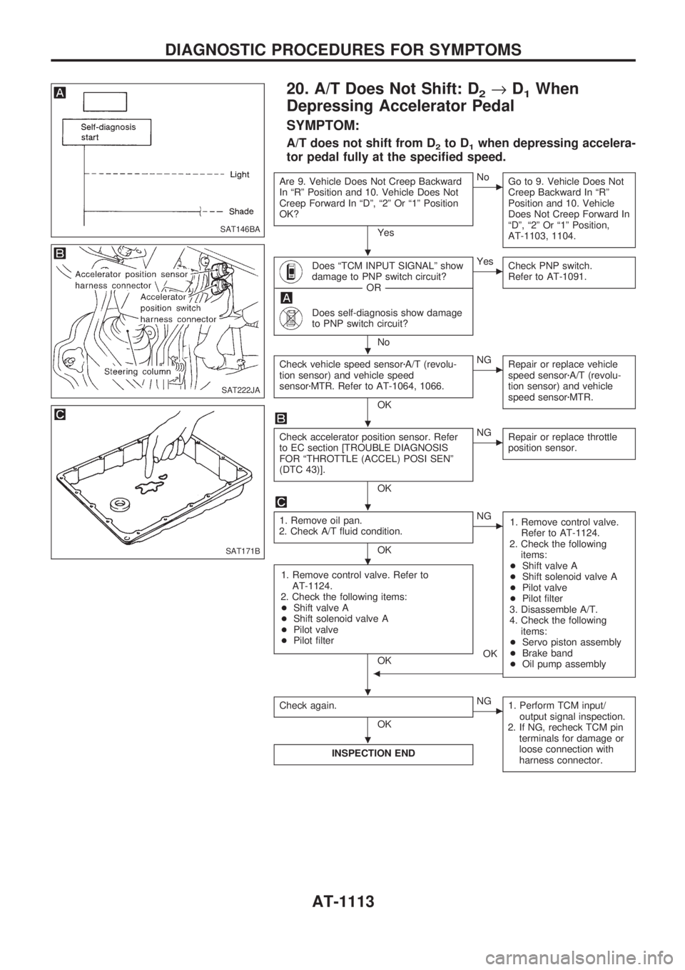
20. A/T Does Not Shift: D2®D1When
Depressing Accelerator Pedal
SYMPTOM:
A/T does not shift from D2to D1when depressing accelera-
tor pedal fully at the specified speed.
Are 9. Vehicle Does Not Creep Backward
In ªRº Position and 10. Vehicle Does Not
Creep Forward In ªDº, ª2º Or ª1º Position
OK?
Yes
cNo
Go to 9. Vehicle Does Not
Creep Backward In ªRº
Position and 10. Vehicle
Does Not Creep Forward In
ªDº, ª2º Or ª1º Position,
AT-1103, 1104.
Does ªTCM INPUT SIGNALº show
damage to PNP switch circuit?
------------------------------------------------------------------------------------------------------------------------------------OR------------------------------------------------------------------------------------------------------------------------------------
Does self-diagnosis show damage
to PNP switch circuit?
No
cYes
Check PNP switch.
Refer to AT-1091.
Check vehicle speed sensorzA/T (revolu-
tion sensor) and vehicle speed
sensorzMTR. Refer to AT-1064, 1066.
OK
cNG
Repair or replace vehicle
speed sensorzA/T (revolu-
tion sensor) and vehicle
speed sensorzMTR.
Check accelerator position sensor. Refer
to EC section [TROUBLE DIAGNOSIS
FOR ªTHROTTLE (ACCEL) POSI SENº
(DTC 43)].
OK
cNG
Repair or replace throttle
position sensor.
1. Remove oil pan.
2. Check A/T fluid condition.
OK
cNG
1. Remove control valve.
Refer to AT-1124.
2. Check the following
items:
+Shift valve A
+Shift solenoid valve A
+Pilot valve
+Pilot filter
3. Disassemble A/T.
4. Check the following
items:
+Servo piston assembly
+Brake band
+Oil pump assembly
1. Remove control valve. Refer to
AT-1124.
2. Check the following items:
+Shift valve A
+Shift solenoid valve A
+Pilot valve
+Pilot filter
OK
b
OK
Check again.
OK
cNG
1. Perform TCM input/
output signal inspection.
2. If NG, recheck TCM pin
terminals for damage or
loose connection with
harness connector.
INSPECTION END
SAT146BA
SAT222JA
SAT171B
.
.
.
.
.
.
.
DIAGNOSTIC PROCEDURES FOR SYMPTOMS
AT-1113
Page 118 of 1033
Description
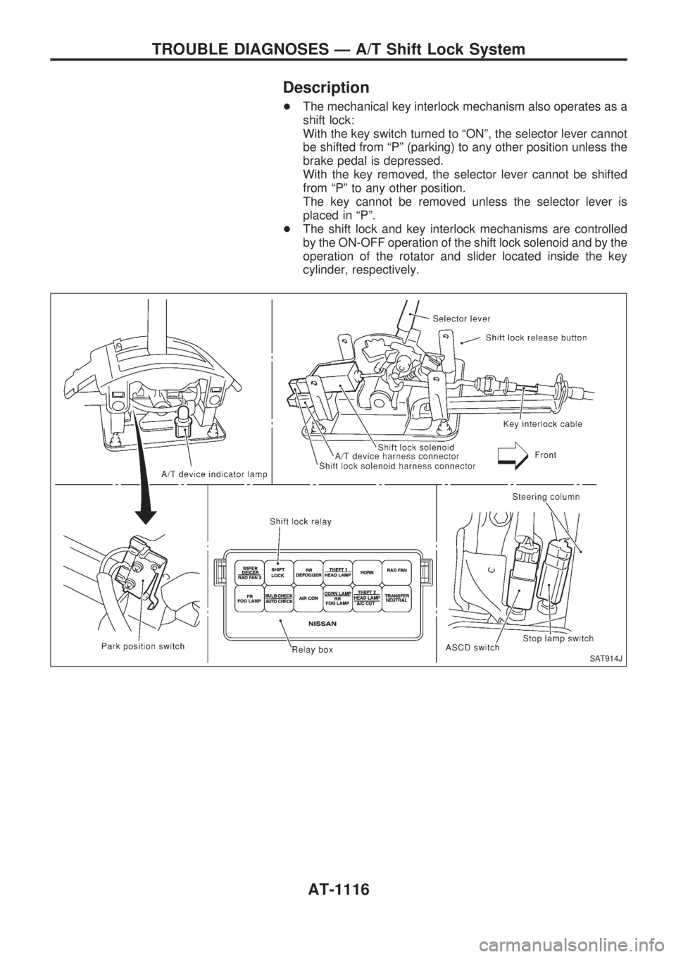
+The mechanical key interlock mechanism also operates as a
shift lock:
With the key switch turned to ªONº, the selector lever cannot
be shifted from ªPº (parking) to any other position unless the
brake pedal is depressed.
With the key removed, the selector lever cannot be shifted
from ªPº to any other position.
The key cannot be removed unless the selector lever is
placed in ªPº.
+The shift lock and key interlock mechanisms are controlled
by the ON-OFF operation of the shift lock solenoid and by the
operation of the rotator and slider located inside the key
cylinder, respectively.
SAT914J
TROUBLE DIAGNOSES Ð A/T Shift Lock System
AT-1116
Page 122 of 1033
VB
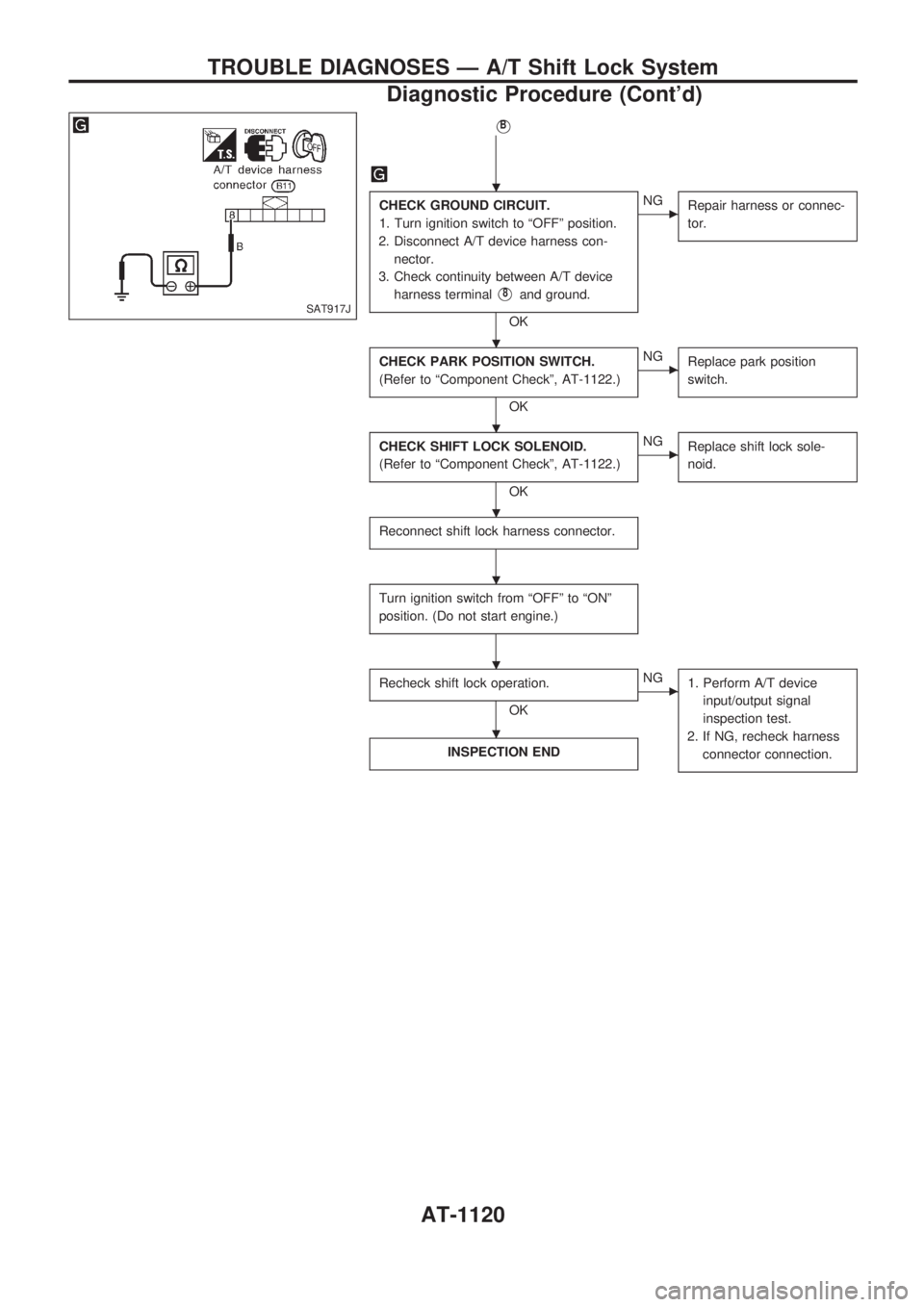
CHECK GROUND CIRCUIT.
1. Turn ignition switch to ªOFFº position.
2. Disconnect A/T device harness con-
nector.
3. Check continuity between A/T device
harness terminal
V8and ground.
OK
cNG
Repair harness or connec-
tor.
CHECK PARK POSITION SWITCH.
(Refer to ªComponent Checkº, AT-1122.)
OK
cNG
Replace park position
switch.
CHECK SHIFT LOCK SOLENOID.
(Refer to ªComponent Checkº, AT-1122.)
OK
cNG
Replace shift lock sole-
noid.
Reconnect shift lock harness connector.
Turn ignition switch from ªOFFº to ªONº
position. (Do not start engine.)
Recheck shift lock operation.
OK
cNG
1. Perform A/T device
input/output signal
inspection test.
2. If NG, recheck harness
connector connection.
INSPECTION END
SAT917J
.
.
.
.
.
.
.
TROUBLE DIAGNOSES Ð A/T Shift Lock System
Diagnostic Procedure (Cont'd)
AT-1120
Page 124 of 1033
INSTALLATION
1. Set key interlock cable to steering lock assembly and install
lock plate.
2. Clamp cable to steering column and fix to control cable with
band.
3. Set selector lever to P position.
4. Insert interlock rod into adjuster holder.
5. Install casing cap to bracket.
6. Move slider in order to fix adjuster holder to interlock rod.
Component Check
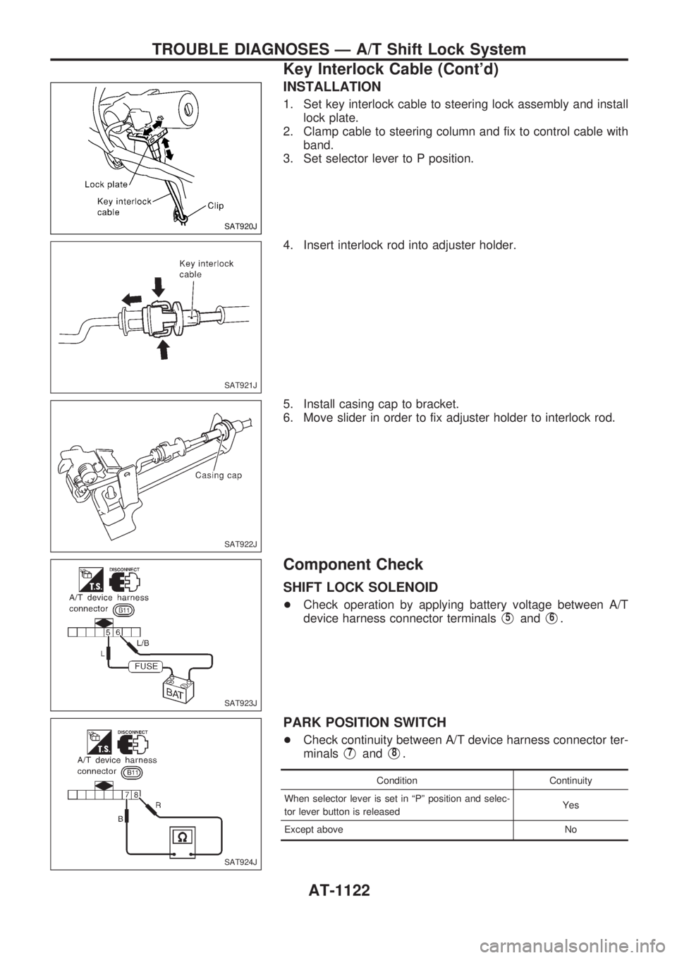
SHIFT LOCK SOLENOID
+Check operation by applying battery voltage between A/T
device harness connector terminals
V5andV6.
PARK POSITION SWITCH
+Check continuity between A/T device harness connector ter-
minals
V7andV8.
Condition Continuity
When selector lever is set in ªPº position and selec-
tor lever button is releasedYes
Except above No
SAT920J
SAT921J
SAT922J
SAT923J
SAT924J
TROUBLE DIAGNOSES Ð A/T Shift Lock System
Key Interlock Cable (Cont'd)
AT-1122
Page 126 of 1033
Control Valve Assembly and Accumulators
REMOVAL
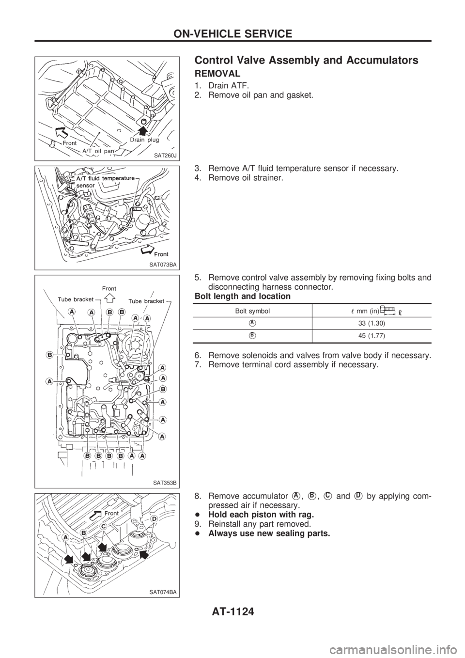
1. Drain ATF.
2. Remove oil pan and gasket.
3. Remove A/T fluid temperature sensor if necessary.
4. Remove oil strainer.
5. Remove control valve assembly by removing fixing bolts and
disconnecting harness connector.
Bolt length and location
Bolt symbol!mm (in)
VA33 (1.30)
VB45 (1.77)
6. Remove solenoids and valves from valve body if necessary.
7. Remove terminal cord assembly if necessary.
8. Remove accumulator
VA,VB,VCandVDby applying com-
pressed air if necessary.
+Hold each piston with rag.
9. Reinstall any part removed.
+Always use new sealing parts.
SAT260J
SAT073BA
SAT353B
SAT074BA
ON-VEHICLE SERVICE
AT-1124
Page 129 of 1033
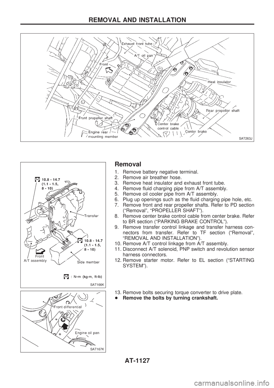
Removal
1. Remove battery negative terminal.
2. Remove air breather hose.
3. Remove heat insulator and exhaust front tube.
4. Remove fluid charging pipe from A/T assembly.
5. Remove oil cooler pipe from A/T assembly.
6. Plug up openings such as the fluid charging pipe hole, etc.
7. Remove front and rear propeller shafts. Refer to PD section
(ªRemovalº, ªPROPELLER SHAFTº).
8. Remove center brake control cable from center brake. Refer
to BR section (ªPARKING BRAKE CONTROLº).
9. Remove transfer control linkage and transfer harness con-
nectors from transfer. Refer to TF section (ªRemovalº,
ªREMOVAL AND INSTALLATIONº).
10. Remove A/T control linkage from A/T assembly.
11. Disconnect A/T solenoid, PNP switch and revolution sensor
harness connectors.
12. Remove starter motor. Refer to EL section (ªSTARTING
SYSTEMº).
13. Remove bolts securing torque converter to drive plate.
+Remove the bolts by turning crankshaft.
SAT263J
SAT166K
SAT167K
REMOVAL AND INSTALLATION
AT-1127
Page 136 of 1033
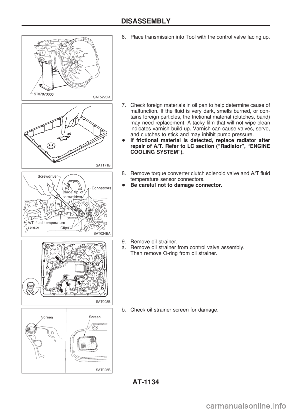
6. Place transmission into Tool with the control valve facing up.
7. Check foreign materials in oil pan to help determine cause of
malfunction. If the fluid is very dark, smells burned, or con-
tains foreign particles, the frictional material (clutches, band)
may need replacement. A tacky film that will not wipe clean
indicates varnish build up. Varnish can cause valves, servo,
and clutches to stick and may inhibit pump pressure.
+If frictional material is detected, replace radiator after
repair of A/T. Refer to LC section (ªRadiatorº, ªENGINE
COOLING SYSTEMº).
8. Remove torque converter clutch solenoid valve and A/T fluid
temperature sensor connectors.
+Be careful not to damage connector.
9. Remove oil strainer.
a. Remove oil strainer from control valve assembly.
Then remove O-ring from oil strainer.
b. Check oil strainer screen for damage.
SAT522GA
SAT171B
SAT024BA
SAT008B
SAT025B
DISASSEMBLY
AT-1134
Page 137 of 1033
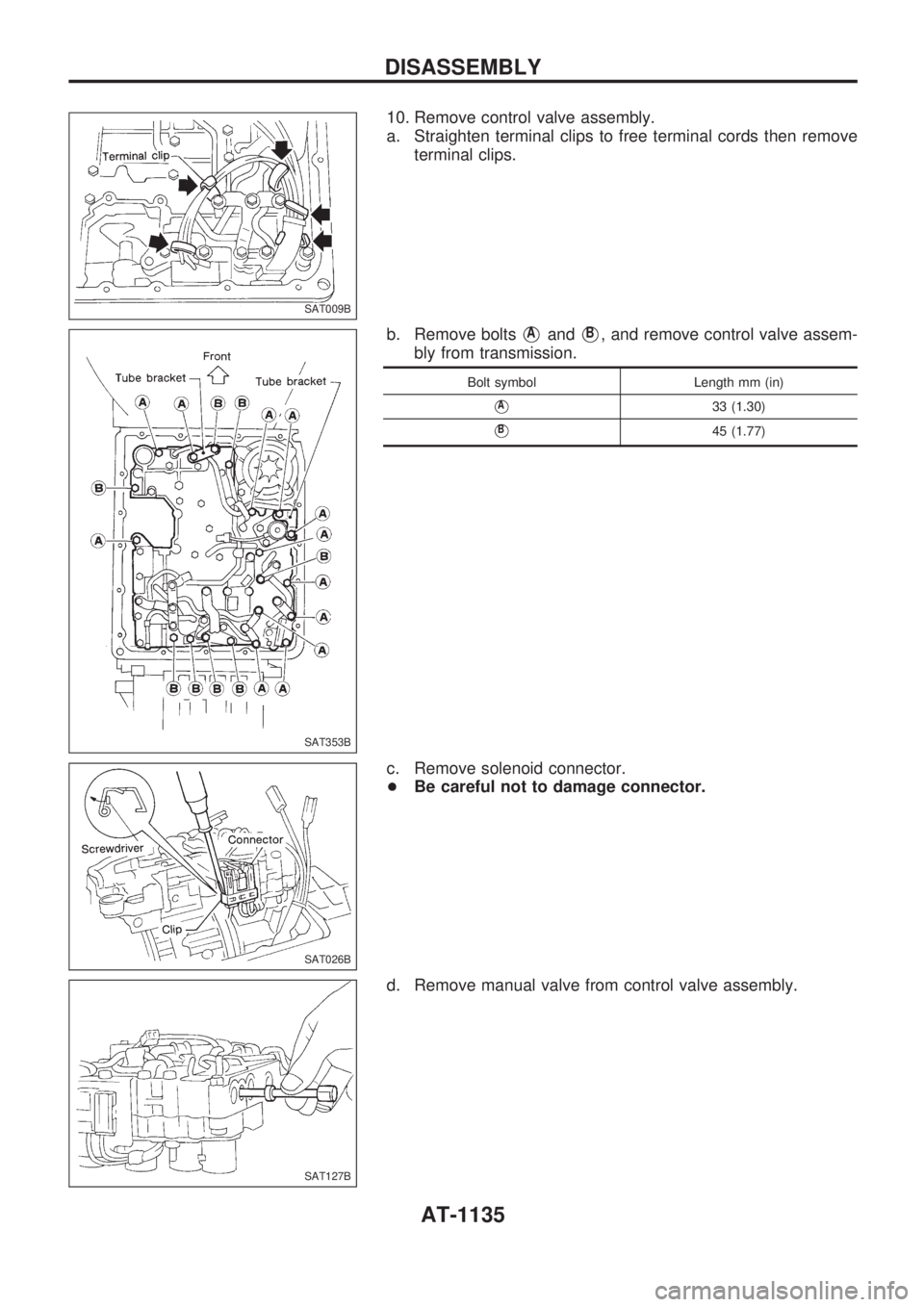
10. Remove control valve assembly.
a. Straighten terminal clips to free terminal cords then remove
terminal clips.
b. Remove bolts
VAandVB, and remove control valve assem-
bly from transmission.
Bolt symbol Length mm (in)
VA33 (1.30)
VB45 (1.77)
c. Remove solenoid connector.
+Be careful not to damage connector.
d. Remove manual valve from control valve assembly.
SAT009B
SAT353B
SAT026B
SAT127B
DISASSEMBLY
AT-1135