Page 303 of 1033

TER-
MINAL
NO.WIRE
COLORITEM CONDITIONDATA (DC Voltage and Pulse
Signal)
5 Y/B TachometerEngine is running.
Warm-up condition
Idle speedApproximately 5.7V
SEF255Z
Engine is running.
Warm-up condition
Engine speed is 2,000 rpmApproximately 6V
SEF256Z
11 BR/YExhaust gas control
valve control solenoid
valveEngine is running.
Engine speed is below 1,200 rpm
Engine coolant temperature is below 87ÉC
(189ÉF)
Stop the vehicle
Heat up switch is ªONºApproximately 0.1V
Engine is running.
Except the above conditionBATTERY VOLTAGE
(11 - 14V)
14 L Cooling fan relayEngine is running.
Cooling fan is not operatingBATTERY VOLTAGE
(11 - 14V)
Engine is running.
Cooling fan is operatingApproximately 0.1V
15 Y/L Air conditioner relayEngine is running.
Air conditioner switch is ªOFFºBATTERY VOLTAGE
(11 - 14V)
Engine is running.
Both air conditioner switch and blower fan
switch are ªONº
(Compressor is operating)Approximately 0.1V
16 L/W Glow lampIgnition switch ªONº
Glow lamp is ªONºApproximately 1V
Ignition switch ªONº
Glow lamp is ªOFFºBATTERY VOLTAGE
(11 - 14V)
TROUBLE DIAGNOSIS Ð GENERAL DESCRIPTIONZD30DDTi
ECM Terminals and Reference Value (Cont'd)
EC-1070
Page 307 of 1033

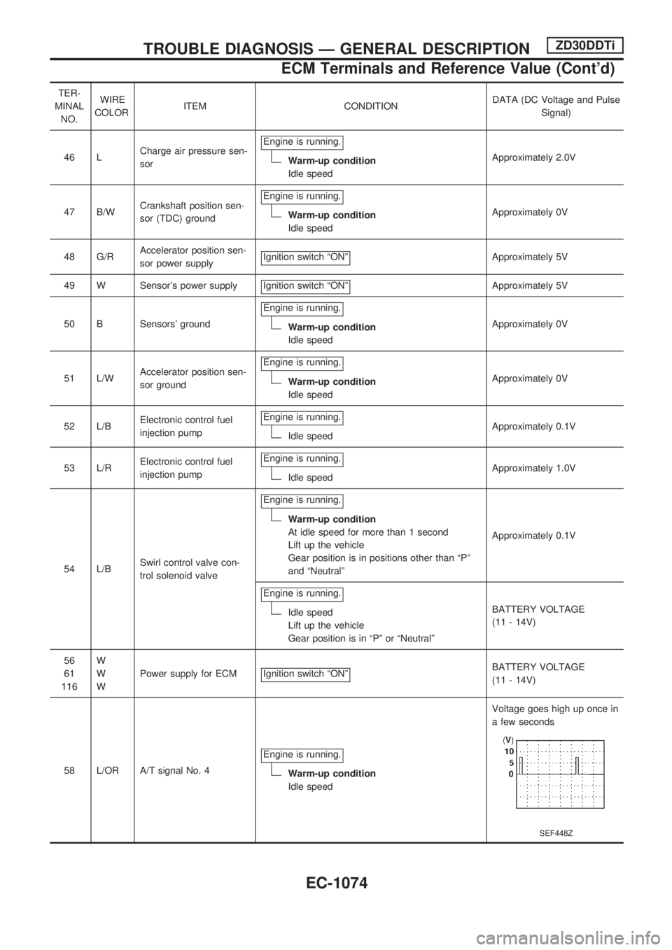
TER-
MINAL
NO.WIRE
COLORITEM CONDITIONDATA (DC Voltage and Pulse
Signal)
46 LCharge air pressure sen-
sorEngine is running.
Warm-up condition
Idle speedApproximately 2.0V
47 B/WCrankshaft position sen-
sor (TDC) groundEngine is running.
Warm-up condition
Idle speedApproximately 0V
48 G/RAccelerator position sen-
sor power supplyIgnition switch ªONº
Approximately 5V
49 W Sensor's power supply Ignition switch ªONº
Approximately 5V
50 B Sensors' groundEngine is running.
Warm-up condition
Idle speedApproximately 0V
51 L/WAccelerator position sen-
sor groundEngine is running.
Warm-up condition
Idle speedApproximately 0V
52 L/BElectronic control fuel
injection pumpEngine is running.
Idle speedApproximately 0.1V
53 L/RElectronic control fuel
injection pumpEngine is running.
Idle speedApproximately 1.0V
54 L/BSwirl control valve con-
trol solenoid valveEngine is running.
Warm-up condition
At idle speed for more than 1 second
Lift up the vehicle
Gear position is in positions other than ªPº
and ªNeutralºApproximately 0.1V
Engine is running.
Idle speed
Lift up the vehicle
Gear position is in ªPº or ªNeutralºBATTERY VOLTAGE
(11 - 14V)
56
61
116W
W
WPower supply for ECM Ignition switch ªONº
BATTERY VOLTAGE
(11 - 14V)
58 L/OR A/T signal No. 4Engine is running.
Warm-up condition
Idle speedVoltage goes high up once in
a few seconds
SEF448Z
TROUBLE DIAGNOSIS Ð GENERAL DESCRIPTIONZD30DDTi
ECM Terminals and Reference Value (Cont'd)
EC-1074
Page 308 of 1033

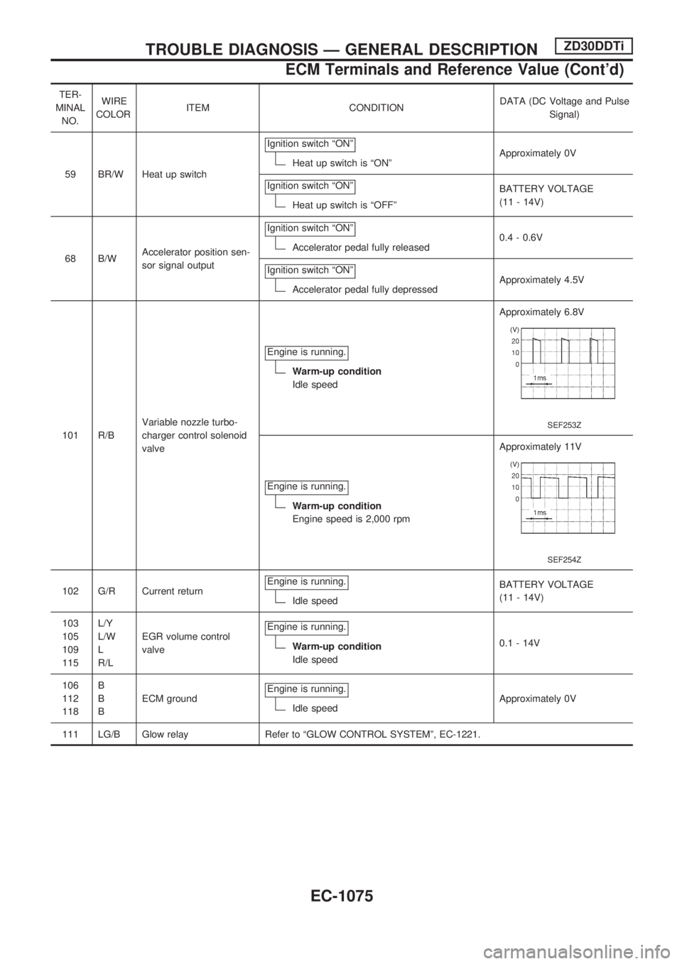
TER-
MINAL
NO.WIRE
COLORITEM CONDITIONDATA (DC Voltage and Pulse
Signal)
59 BR/W Heat up switchIgnition switch ªONº
Heat up switch is ªONºApproximately 0V
Ignition switch ªONº
Heat up switch is ªOFFºBATTERY VOLTAGE
(11 - 14V)
68 B/WAccelerator position sen-
sor signal outputIgnition switch ªONº
Accelerator pedal fully released0.4 - 0.6V
Ignition switch ªONº
Accelerator pedal fully depressedApproximately 4.5V
101 R/BVariable nozzle turbo-
charger control solenoid
valveEngine is running.
Warm-up condition
Idle speedApproximately 6.8V
SEF253Z
Engine is running.
Warm-up condition
Engine speed is 2,000 rpmApproximately 11V
SEF254Z
102 G/R Current returnEngine is running.Idle speedBATTERY VOLTAGE
(11 - 14V)
103
105
109
115L/Y
L/W
L
R/LEGR volume control
valveEngine is running.
Warm-up condition
Idle speed0.1 - 14V
106
112
118B
B
BECM groundEngine is running.
Idle speedApproximately 0V
111 LG/B Glow relay Refer to ªGLOW CONTROL SYSTEMº, EC-1221.
TROUBLE DIAGNOSIS Ð GENERAL DESCRIPTIONZD30DDTi
ECM Terminals and Reference Value (Cont'd)
EC-1075
Page 479 of 1033

Description
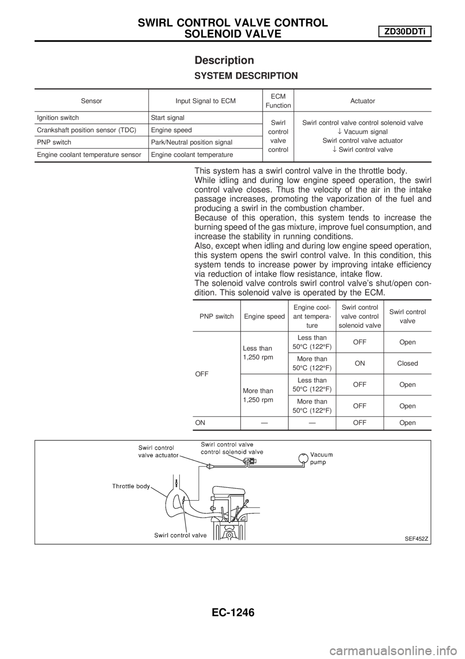
SYSTEM DESCRIPTION
Sensor Input Signal to ECMECM
FunctionActuator
Ignition switch Start signal
Swirl
control
valve
controlSwirl control valve control solenoid valve
¯Vacuum signal
Swirl control valve actuator
¯Swirl control valve Crankshaft position sensor (TDC) Engine speed
PNP switch Park/Neutral position signal
Engine coolant temperature sensor Engine coolant temperature
This system has a swirl control valve in the throttle body.
While idling and during low engine speed operation, the swirl
control valve closes. Thus the velocity of the air in the intake
passage increases, promoting the vaporization of the fuel and
producing a swirl in the combustion chamber.
Because of this operation, this system tends to increase the
burning speed of the gas mixture, improve fuel consumption, and
increase the stability in running conditions.
Also, except when idling and during low engine speed operation,
this system opens the swirl control valve. In this condition, this
system tends to increase power by improving intake efficiency
via reduction of intake flow resistance, intake flow.
The solenoid valve controls swirl control valve's shut/open con-
dition. This solenoid valve is operated by the ECM.
PNP switch Engine speedEngine cool-
ant tempera-
tureSwirl control
valve control
solenoid valveSwirl control
valve
OFFLess than
1,250 rpmLess than
50ÉC (122ÉF)OFF Open
More than
50ÉC (122ÉF)ON Closed
More than
1,250 rpmLess than
50ÉC (122ÉF)OFF Open
More than
50ÉC (122ÉF)OFF Open
ON Ð Ð OFF Open
SEF452Z
SWIRL CONTROL VALVE CONTROL
SOLENOID VALVEZD30DDTi
EC-1246
Page 480 of 1033

COMPONENT DESCRIPTION
Swirl control valve control solenoid valve
The swirl control valve control solenoid valve responds to signals
from the ECM. When the ECM sends an ON (ground) signal, the
solenoid valve is bypassed to apply vacuum pump vacuum to the
swirl control valve actuator. This operation closes the swirl con-
trol valve. When the ECM sends an OFF signal, the vacuum
signal is cut and the swirl control valve opens.
CONSULT-II Reference Value in Data Monitor
Mode
Specification data are reference values.
MONITOR ITEM CONDITION SPECIFICATION
SWRL CONT S/V+Lift up the vehicle
+Engine: After warming up, let it
idle for more than 1 second.
+Air conditioner switch: OFF
+No-loadShift lever: Except ªPº and ªNeutralº
positionON
Shift lever: ªNeutralº position OFF
ECM Terminals and Reference Value
Specification data are reference values and are measured between each terminal and ground.
CAUTION:
Do not use ECM ground terminals when measuring input/output voltage. Doing so may damage the
ECM's transistor. Use a ground other than ECM terminals, such as the ground.
TER-
MINAL
NO.WIRE
COLORITEM CONDITIONDATA
(DC Voltage and Pulse
Signal)
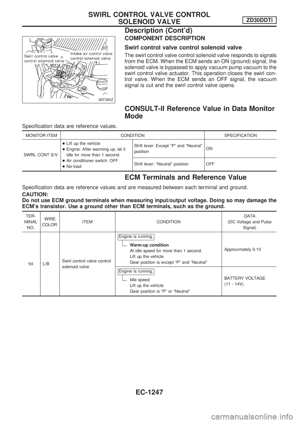
54 L/BSwirl control valve control
solenoid valveEngine is running.
Warm-up condition
At idle speed for more than 1 second.
Lift up the vehicle
Gear position is except ªPº and ªNeutralºApproximately 0.1V
Engine is running.
Idle speed
Lift up the vehicle
Gear position is ªPº or ªNeutralºBATTERY VOLTAGE
(11 - 14V)
SEF284Z
SWIRL CONTROL VALVE CONTROL
SOLENOID VALVEZD30DDTi
Description (Cont'd)
EC-1247
Page 481 of 1033
Wiring Diagram
TEC117M
SWIRL CONTROL VALVE CONTROL
SOLENOID VALVEZD30DDTi
EC-1248
Page 482 of 1033
Diagnostic Procedure
1 INSPECTION START
Do you have CONSULT-II?
Yes or No
YescGO TO 2.
NocGO TO 3.
2 CHECK OVERALL FUNCTION
With CONSULT-II
1. Start engine and let it idle.
2. Select ªSWIRL CONT S/V 1º in ªACTIVE TESTº mode with CONSULT-II.
3. Touch ªONº and ªOFFº alternately on CONSULT-II screen.
4. Make sure that swirl control valve actuator rod moves according to ªSWIRL CONT S/V 1º indication.
SEF307Z
OK or NG
OKcINSPECTION END
NGcGO TO 4.
3 CHECK OVERALL FUNCTION
Without CONSULT-II
1. Lift up the vehicle.
2. Start engine and warm it up to normal operating temperature.
3. Run engine at idle speed.
4. Make sure that swirl control valve actuator rod moves when shifting the shift lever to ªPº or ªNeutralº position and then to posi-
tions other than ªPº and ªNeutralº.
SEF308Z
OK or NG
OKcINSPECTION END
NGcGO TO 5.
SWIRL CONTROL VALVE CONTROL
SOLENOID VALVEZD30DDTi
EC-1249
Page 483 of 1033
4 CHECK VACUUM SOURCE
With CONSULT-II
1. Turn ignition switch ªOFFº.
2. Disconnect vacuum hose connected to swirl control valve actuator.
3. Start engine and let it idle.
4. Select ªSWIRL CONT S/V 1º in ªACTIVE TESTº mode with CONSULT-II.
5. Touch ªONº and ªOFFº alternately on CONSULT-II screen.
6. Check vacuum hose for vacuum existence under the following conditions.
SEF309Z
OK or NG
OKcGO TO 7.
NGcGO TO 6.
5 CHECK VACUUM SOURCE
Without CONSULT-II
1. Turn ignition switch ªOFFº.
2. Disconnect vacuum hose connected to swirl control valve actuator.
3. Lift up the vehicle.
4. Start engine and warm it up to normal operating temperature.
5. Run engine at idle speed
6. Check vacuum hose for vacuum existence under the following conditions.
SEF310Z
OK or NG
OKcGO TO 7.
NGcGO TO 6.
SWIRL CONTROL VALVE CONTROL
SOLENOID VALVEZD30DDTi
Diagnostic Procedure (Cont'd)
EC-1250
SWIRL CONT S/V 1 Vacuum
Should exist
Should not exist