2000 MITSUBISHI MONTERO fuel
[x] Cancel search: fuelPage 260 of 1839
GDI -Troubleshooting
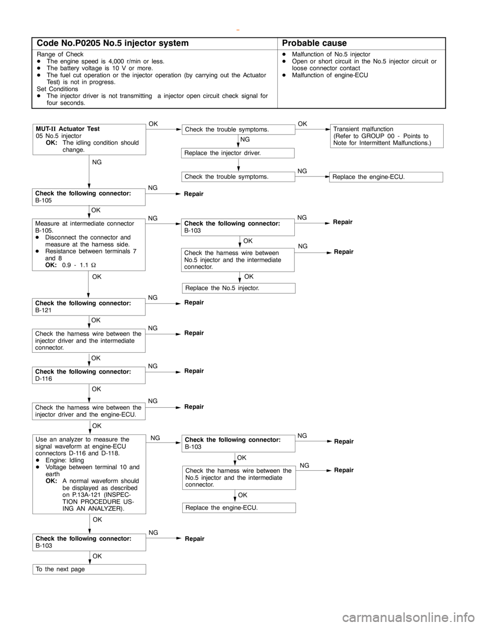
Code No.P0205 No.5 injector systemProbable cause
Range of Check
DThe enginespeed is 4,000 r/min or less.
DThe battery voltage is 10 V or more.
DThe fuel cut operation or the injector operation (by carrying out the Actuator
Test) is not in progress.
Set Conditions
DThe injector driver is not transmitting a injectoropencircuit check signal for
four seconds.DMalfunction of No.5 injector
DOpen or short circuit in the No.5 injector circuit or
loose connector contact
DMalfunction of engine-ECU
NG
Check the following connector:
B-105NG
Repair
OK
NG
Repair
MUT-
IIActuator Test
05 No.5 injector
OK:
The idling condition should
change.OKCheck the trouble symptoms.OKTransient malfunction
(Refer to GROUP 00 - Points to
Note for Intermittent Malfunctions.)
NG
Replace the injector driver.
Check the trouble symptoms.NGReplace the engine-ECU.
OK
Measure at intermediate connector
B-105.
DDisconnect the connector and
measure at the harness side.
DResistance between terminals 7
and 8
OK:
0.9 - 1.1WNGCheck the following connector:
B-103NG
Repair
OK
Replace the No.5 injector.
OK
Check the following connector:
B-121NG
Repair
OK
Check the harness wire between the
injector driver and the intermediate
connector.NG
Repair
OK
Check the following connector:
D-116NG
Repair
OK
Check the harness wire between the
injector driver and the engine-ECU.NG
Repair
OK
Use an analyzer to measure the
signal waveform at engine-ECU
connectors D-116 and D-118.
DEngine: Idling
DVoltage between terminal 10 and
earth
OK:
A normal waveform should
be displayed as described
on P.13A-121 (INSPEC-
TION PROCEDURE US-
ING AN ANALYZER).NGCheck the following connector:
B-103
OK
Check the following connector:
B-103NG
Repair
OK
To the nextpageNG
OK
OK
Check the harness wire between the
No.5 injector and the intermediate
connector.NG
Replace the engine-ECU.
Repair
Repair
Check the harness wire between
No.5 injector and the intermediate
connector.
www.WorkshopManuals.co.uk
Purchased from www.WorkshopManuals.co.uk
Page 262 of 1839
GDI -Troubleshooting
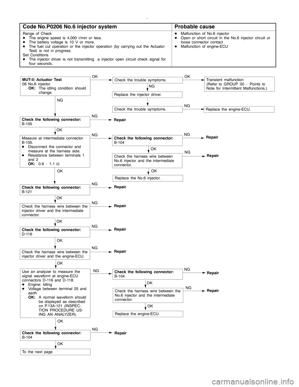
Code No.P0206 No.6 injector systemProbable cause
Range of Check
DThe enginespeed is 4,000 r/min or less.
DThe battery voltage is 10 V or more.
DThe fuel cut operation or the injector operation (by carrying out the Actuator
Test) is not in progress.
Set Conditions
DThe injector driver is not transmitting a injectoropencircuit check signal for
four seconds.DMalfunction of No.6 injector
DOpen or short circuit in the No.6 injector circuit or
loose connector contact
DMalfunction of engine-ECU
NG
Check the following connector:
B-105NG
Repair
OK
NG
Repair
MUT-
IIActuator Test
06 No.6 injector
OK:
The idling condition should
change.OKCheck the trouble symptoms.OKTransient malfunction
(Refer to GROUP 00 - Points to
Note for Intermittent Malfunctions.)
NG
Replace the injector driver.
Check the trouble symptoms.NGReplace the engine-ECU.
OK
Measure at intermediate connector
B-105.
DDisconnect the connector and
measure at the harness side.
DResistance between terminals 1
and 2
OK:
0.9 - 1.1WNGCheck the following connector:
B-104NG
Repair
OK
Replace the No.6 injector.
OK
Check the following connector:
B-121NG
Repair
OK
Check the harness wire between the
injector driver and the intermediate
connector.NG
Repair
OK
Check the following connector:
D-116NG
Repair
OK
Check the harness wire between the
injector driver and the engine-ECU.NG
Repair
OK
Use an analyzer to measure the
signal waveform at engine-ECU
connectors D-116 and D-118.
DEngine: Idling
DVoltage between terminal 25 and
earth
OK:
A normal waveform should
be displayed as described
on P.13A-121 (INSPEC-
TION PROCEDURE US-
ING AN ANALYZER).NGCheck the following connector:
B-104
OK
Check the following connector:
B-104NG
Repair
OK
To the nextpageNG
OK
OK
Check the harness wire between the
No.6 injector and the intermediate
connector.NG
Replace the engine-ECU.
Repair
Repair
Check the harness wire between
No.6 injector and the intermediate
connector.
www.WorkshopManuals.co.uk
Purchased from www.WorkshopManuals.co.uk
Page 275 of 1839
GDI -Troubleshooting
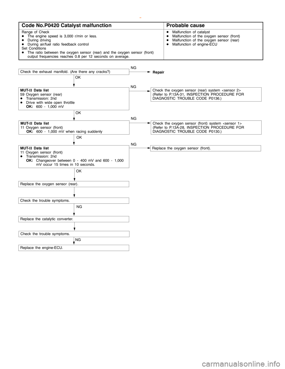
Code No.P0420 Catalyst malfunctionProbable cause
Range of Check
DThe enginespeed is 3,000 r/min or less.
DDuring driving
DDuring air/fuel ratio feedback control
Set Conditions
DThe ratio between the oxygen sensor (rear) and the oxygen sensor (front)
output frequencies reaches 0.8 per 12 seconds on average.DMalfunction of catalyst
DMalfunction of the oxygen sensor (front)
DMalfunction of the oxygen sensor (rear)
DMalfunction of engine-ECU
Check the trouble symptoms.
Check the exhaust manifold. (Are there anycracks?)NG
OK
MUT-
IIData list
59 Oxygen sensor (rear)
DTransmission: 2nd
DDrive with wideopen throttle
OK:
600 - 1,000 mVNGCheck the oxygen sensor (rear) system
(Refer to P.13A-31, INSPECTIONPROCEDURE FOR
DIAGNOSTIC TROUBLE CODE P0136.)
OK
MUT-
IIData list
11 Oxygen sensor (front)
DTransmission: 2nd
OK:
Changeover between 0 - 400 mV and 600 - 1,000
mV occur 15 times in 10 seconds.
OK
Replace the oxygen sensor (rear).
NG
Replace the catalytic converter.
Check the trouble symptoms.
NG
Replace the engine-ECU.
MUT-
IIData list
11 Oxygen sensor (front)
OK:
600 - 1,000 mV when racing suddenly
OK
NGRepair
Check the oxygen sensor (front) system
(Refer to P.13A-28, INSPECTIONPROCEDURE FOR
DIAGNOSTIC TROUBLE CODE P0130.)
Replace the oxygen sensor (front). NG
www.WorkshopManuals.co.uk
Purchased from www.WorkshopManuals.co.uk
Page 277 of 1839
GDI -Troubleshooting
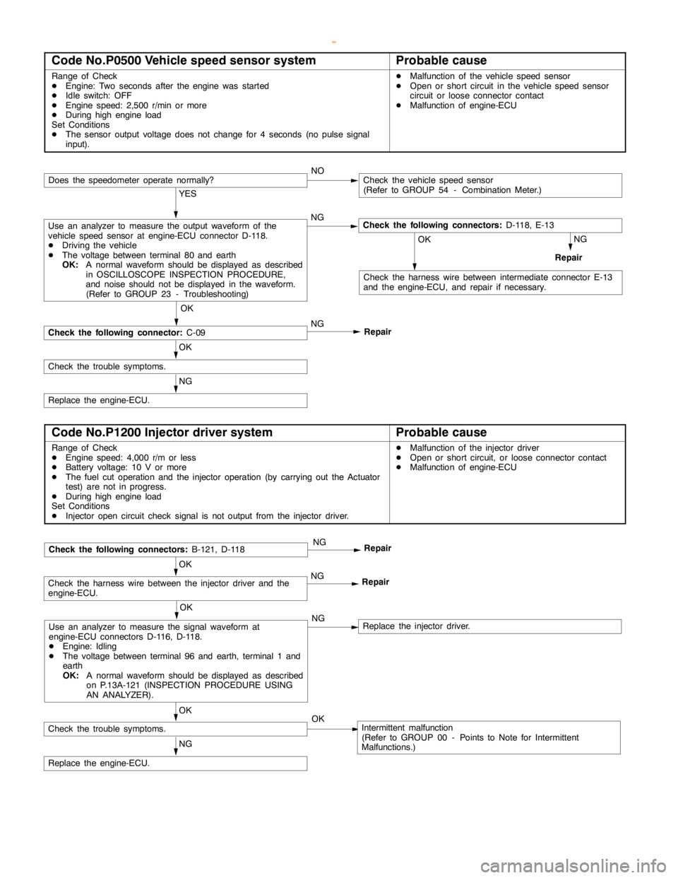
Code No.P0500 Vehicle speed sensor systemProbable cause
Range of Check
DEngine: Two seconds after theengine wasstarted
DIdle switch: OFF
DEngine speed: 2,500 r/min or more
DDuring high engine load
Set Conditions
DThe sensor output voltage does not change for 4 seconds (no pulse signal
input).DMalfunction of the vehicle speed sensor
DOpen or short circuit in the vehicle speed sensor
circuit or loose connector contact
DMalfunction of engine-ECU
NOCheck the vehicle speed sensor
(Refer to GROUP 54 - Combination Meter.)
YES
Use an analyzer to measure the output waveform of the
vehicle speed sensor at engine-ECU connector D-118.
DDriving the vehicle
DThe voltage between terminal 80 and earth
OK:
A normal waveform should be displayed as described
in OSCILLOSCOPE INSPECTION PROCEDURE,
and noise should not be displayed in the waveform.
(Refer to GROUP 23 - Troubleshooting)NGCheck the following connectors:
D-118, E-13
NG
Repair
OK
Check the harness wire between intermediate connector E-13
and the engine-ECU, and repair if necessary.
OK
Check the following connector:
C-09NG
Repair
OK
Check the trouble symptoms.
NG
Replace the engine-ECU.
Does the speedometer operate normally?
Code No.P1200 Injector driver systemProbable cause
Range of Check
DEngine speed: 4,000 r/m or less
DBattery voltage: 10 V or more
DThe fuel cut operation and the injector operation (by carrying out the Actuator
test) are not in progress.
DDuring high engine load
Set Conditions
DInjector opencircuit check signal is not output from the injector driver.DMalfunction of the injector driver
DOpen or short circuit, or loose connector contact
DMalfunction of engine-ECU
OK
Use an analyzer to measure the signal waveform at
engine-ECU connectors D-116, D-118.
DEngine: Idling
DThe voltage between terminal 96 and earth, terminal 1 and
earth
OK:
A normal waveform should be displayed as described
on P.13A-121 (INSPECTIONPROCEDURE USING
AN ANALYZER).NGReplace the injector driver.
OK
Check the harness wire between the injector driver and the
engine-ECU.NG
Repair
NG
Replace the engine-ECU.
Check the following connectors:
B-121, D-118NG
Repair
OK
Check the trouble symptoms.OKIntermittent malfunction
(Refer to GROUP 00 - Points to Note for Intermittent
Malfunctions.)
www.WorkshopManuals.co.uk
Purchased from www.WorkshopManuals.co.uk
Page 291 of 1839
GDI -Troubleshooting
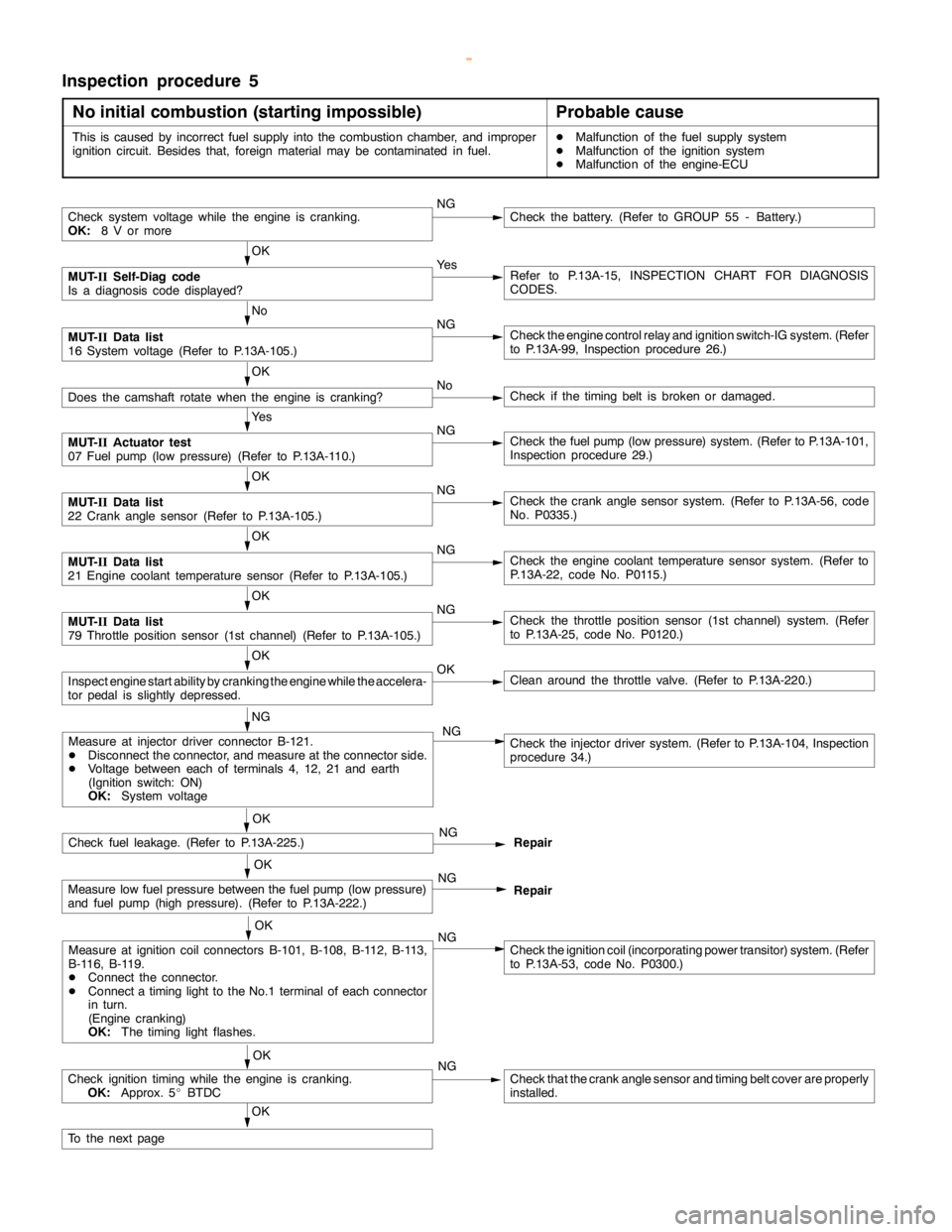
Inspection procedure 5
No initial combustion (starting impossible)
Probable cause
This is caused by incorrect fuel supply into the combustion chamber, and improper
ignition circuit. Besides that, foreign material may be contaminated in fuel.DMalfunction of the fuel supply system
DMalfunction of the ignition system
DMalfunction of the engine-ECU
Check system voltage while theengine iscranking.
OK:
8 V or moreNGCheck the battery. (Refer to GROUP 55 - Battery.)
OK
MUT-
IISelf-Diag code
Is a diagnosis code displayed?Ye sRefer to P.13A-15, INSPECTION CHART FOR DIAGNOSIS
CODES.
No
MUT-
IIData list
16 System voltage (Refer to P.13A-105.)NGCheck theengine controlrelay and ignition switch-IG system. (Refer
to P.13A-99, Inspection procedure 26.)
OK
Does the camshaft rotate when theengine is cranking?NoCheck if thetiming belt isbroken ordamaged.
Ye s
MUT-
IIActuator test
07 Fuel pump(low pressure) (Refer to P.13A-110.)NGCheck the fuelpump(low pressure) system. (Refer to P.13A-101,
Inspection procedure 29.)
OK
MUT-
IIData list
22 Crankanglesensor (Refer to P.13A-105.)NGCheck the crankanglesensor system. (Refer to P.13A-56, code
No. P0335.)
OK
MUT-
IIData list
21 Engine coolant temperature sensor (Refer to P.13A-105.)NGCheck theengine coolant temperaturesensor system. (Refer to
P.13A-22, code No. P0115.)
OK
MUT-
IIData list
79 Throttle position sensor (1st channel) (Refer to P.13A-105.)NGCheck the throttle position sensor (1st channel) system. (Refer
to P.13A-25, code No. P0120.)
OK
Inspectenginestart ability by cranking theengine while theaccelera-
tor pedal isslightly depressed.OKClean around the throttle valve. (Refer to P.13A-220.)
NG
Check fuel leakage. (Refer to P.13A-225.)NG
Repair
OK
Measure low fuel pressure between the fuelpump(low pressure)
and fuel pump (highpressure). (Refer to P.13A-222.)NG
Repair
OK
Measure at ignition coil connectors B-101, B-108, B-112, B-113,
B-116, B-119.
DConnect the connector.
DConnect atiming light to theNo.1 terminal of each connector
in turn.
(Engine cranking)
OK:
The timing lightflashes.NGCheck the ignition coil (incorporating power transitor) system. (Refer
to P.13A-53, code No. P0300.)
OK
Check ignitiontiming while the engine iscranking.
OK:
Approx. 5_BTDCNGCheck that the crankanglesensor andtiming beltcover are properly
installed.
OK
To the nextpage
Measure at injector driver connector B-121.
DDisconnect the connector, and measure at the connector side.
DVoltage between each of terminals 4, 12, 21 and earth
(Ignition switch: ON)
OK:
System voltageCheck the injector driver system. (Refer to P.13A-104, Inspection
procedure 34.) NG
OK
www.WorkshopManuals.co.uk
Purchased from www.WorkshopManuals.co.uk
Page 292 of 1839
GDI -Troubleshooting
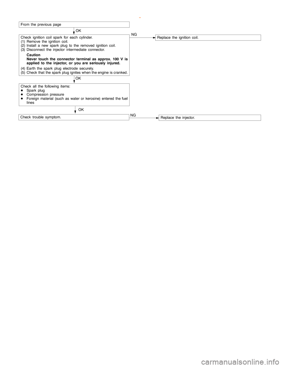
OK
Check ignition coil spark for each cylinder.
(1) Remove the ignition coil.
(2) Install a new sparkplug to the removed ignitioncoil.
(3) Disconnect the injector intermediate connector.
Caution
Never touch the connector terminal as approx. 100 V is
applied to the injector, or you are seriously injured.
(4) Earth the sparkplug electrodesecurely.
(5) Check that the sparkplug igniteswhen theengine iscranked.NGReplace the ignition coil.
OK
Check all the following items:
DSparkplug
DCompression pressure
DForeign material (such as water or kerosine) entered the fuel
lines
Check trouble symptom.OKNGReplace the injector.
From the previouspage
www.WorkshopManuals.co.uk
Purchased from www.WorkshopManuals.co.uk
Page 293 of 1839
GDI -Troubleshooting
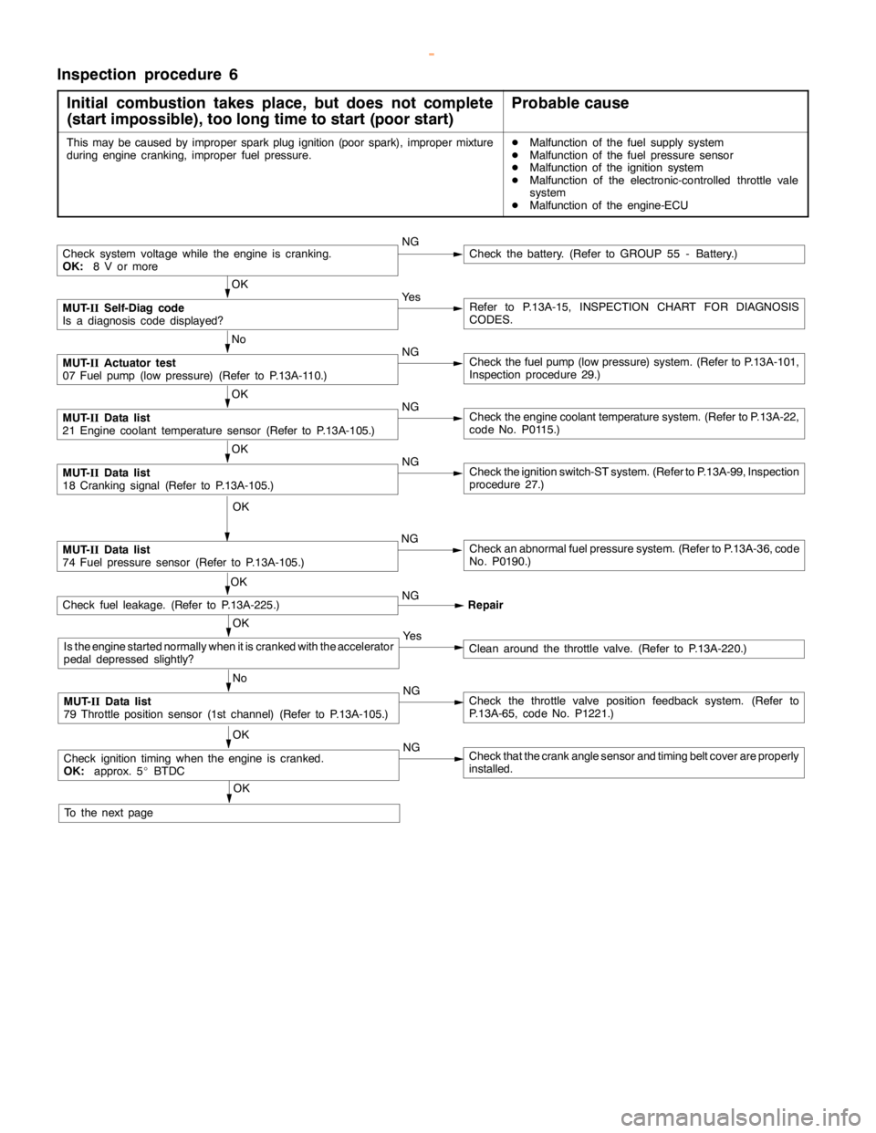
Inspection procedure 6
Initial combustion takes place, but does not complete
(start impossible), too long time to start (poor start)
Probable cause
This may be caused by improper sparkplug ignition (poorspark), improper mixture
during enginecranking, improper fuel pressure.DMalfunction of the fuel supply system
DMalfunction of the fuel pressure sensor
DMalfunction of the ignition system
DMalfunction of the electronic-controlled throttle vale
system
DMalfunction of the engine-ECU
Check system voltage while theengine iscranking.
OK:
8 V or moreNGCheck the battery. (Refer to GROUP 55 - Battery.)
OK
MUT-
IISelf-Diag code
Is a diagnosis code displayed?Ye sRefer to P.13A-15, INSPECTION CHART FOR DIAGNOSIS
CODES.
No
MUT-
IIActuator test
07 Fuel pump(low pressure) (Refer to P.13A-110.)NGCheck the fuelpump(low pressure) system. (Refer to P.13A-101,
Inspection procedure 29.)
OK
MUT-
IIData list
21 Engine coolant temperature sensor (Refer to P.13A-105.)NGCheck theengine coolant temperaturesystem. (Refer to P.13A-22,
code No. P0115.)
OK
MUT-
IIData list
18 Cranking signal (Refer to P.13A-105.)NGCheck the ignition switch-ST system. (Refer to P.13A-99, Inspection
procedure 27.)
OK
MUT-
IIData list
74 Fuel pressure sensor (Refer to P.13A-105.)NGCheck an abnormal fuel pressure system. (Refer to P.13A-36, code
No. P0190.)
Check fuel leakage. (Refer to P.13A-225.)NG
Repair
OK
Is the enginestarted normally when it is cranked with the accelerator
pedal depressed slightly?Ye sClean around the throttle valve. (Refer to P.13A-220.)
No
MUT-
IIData list
79 Throttle position sensor (1st channel) (Refer to P.13A-105.)NGCheck the throttle valve position feedback system. (Refer to
P.13A-65, code No. P1221.)
OK
Check ignitiontimingwhen theengine iscranked.
OK:
approx. 5_BTDCNGCheck that the crankanglesensor andtiming beltcover are properly
installed.
OK
To the nextpageOK
www.WorkshopManuals.co.uk
Purchased from www.WorkshopManuals.co.uk
Page 294 of 1839
GDI -Troubleshooting
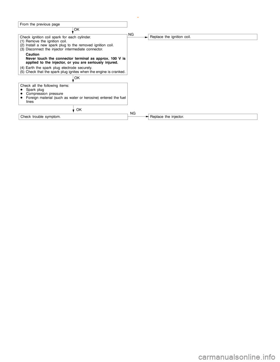
OK
Check ignition coil spark for each cylinder.
(1) Remove the ignition coil.
(2) Install a new sparkplug to the removed ignitioncoil.
(3) Disconnect the injector intermediate connector.
Caution
Never touch the connector terminal as approx. 100 V is
applied to the injector, or you are seriously injured.
(4) Earth the sparkplug electrodesecurely.
(5) Check that the sparkplug igniteswhen theengine iscranked.NGReplace the ignition coil.
OK
Check all the following items:
DSparkplug
DCompression pressure
DForeign material (such as water or kerosine) entered the fuel
lines
Check trouble symptom.OKNGReplace the injector.
From the previouspage
www.WorkshopManuals.co.uk
Purchased from www.WorkshopManuals.co.uk