2000 MITSUBISHI MONTERO catalytic converter
[x] Cancel search: catalytic converterPage 275 of 1839

GDI -Troubleshooting
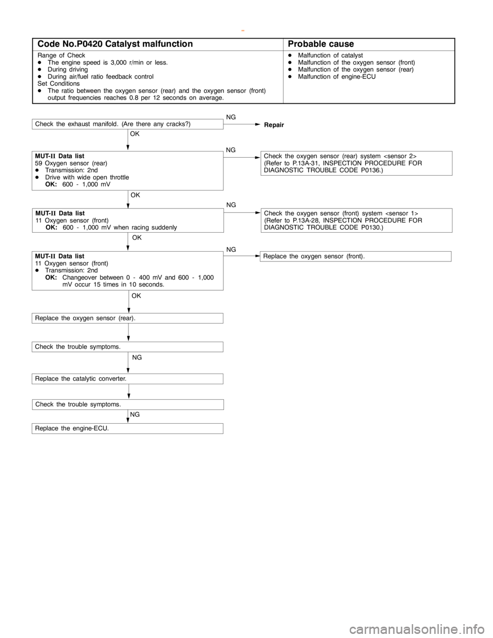
Code No.P0420 Catalyst malfunctionProbable cause
Range of Check
DThe enginespeed is 3,000 r/min or less.
DDuring driving
DDuring air/fuel ratio feedback control
Set Conditions
DThe ratio between the oxygen sensor (rear) and the oxygen sensor (front)
output frequencies reaches 0.8 per 12 seconds on average.DMalfunction of catalyst
DMalfunction of the oxygen sensor (front)
DMalfunction of the oxygen sensor (rear)
DMalfunction of engine-ECU
Check the trouble symptoms.
Check the exhaust manifold. (Are there anycracks?)NG
OK
MUT-
IIData list
59 Oxygen sensor (rear)
DTransmission: 2nd
DDrive with wideopen throttle
OK:
600 - 1,000 mVNGCheck the oxygen sensor (rear) system
(Refer to P.13A-31, INSPECTIONPROCEDURE FOR
DIAGNOSTIC TROUBLE CODE P0136.)
OK
MUT-
IIData list
11 Oxygen sensor (front)
DTransmission: 2nd
OK:
Changeover between 0 - 400 mV and 600 - 1,000
mV occur 15 times in 10 seconds.
OK
Replace the oxygen sensor (rear).
NG
Replace the catalytic converter.
Check the trouble symptoms.
NG
Replace the engine-ECU.
MUT-
IIData list
11 Oxygen sensor (front)
OK:
600 - 1,000 mV when racing suddenly
OK
NGRepair
Check the oxygen sensor (front) system
(Refer to P.13A-28, INSPECTIONPROCEDURE FOR
DIAGNOSTIC TROUBLE CODE P0130.)
Replace the oxygen sensor (front). NG
www.WorkshopManuals.co.uk
Purchased from www.WorkshopManuals.co.uk
Page 307 of 1839

GDI -Troubleshooting
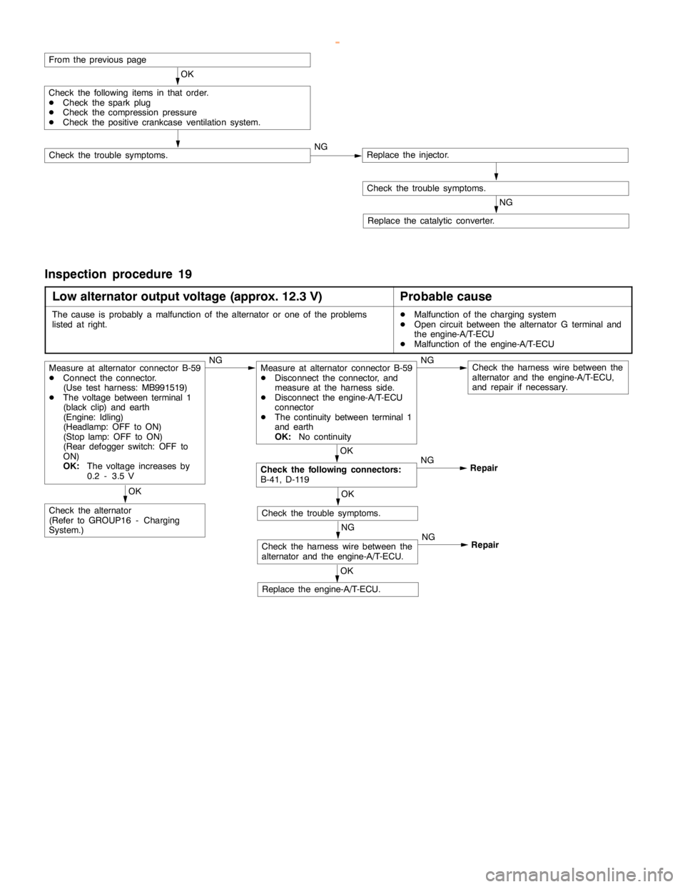
From the previouspage
OK
MUT-
IIData list
68 EGR valve (Refer to P.13A-105.)NGCheck the EGR valve system. (Refer to P.13A-60, code No. P0403.)
OK
MUT-
IIActuator test
08 Purge control solenoid valve (Refer to P.13A-110.)NGCheck purge control solenoid valve system. (Refer to P.13A-62,
code No. P0443.)
OK
Check trouble symptom.NGReplace the injector.
Check trouble symptom.
NG
Replace the three-way catalytic converter.
www.WorkshopManuals.co.uk
Purchased from www.WorkshopManuals.co.uk
Page 400 of 1839

Page 464 of 1839

15
DRIVE CYCLE
Performing the running test of the car using the following five drive cycle patterns makes it possible to
monitor all the diagnosis codes that are required for operation of the car in order to determine if the
applicable system is operating properly or not.
In other words, doing such a drive allows to regenerate any kind of trouble which involves illuminating the
Engine Warning Lamp (Check Engine Lamp) and to verify the repair procedure has eliminated the trouble
[the Engine Warning Lamp (Check Engine Lamp) is no longer illuminated].
Caution
Two technicians should always be in the vehicle when carrying out a test drive.
NOTE
Check that the diagnosis code is not output before traveling in the Drive cycle pattern. Erase the diagnosis
code if it has been output.
DRIVE CYCLE PATTERN LIST
PROCEDURE MONITOR ITEM DIAGNOSIS CODE
Catalytic converter monitor P04201
Heated oxygen sensor
2 Fuel trim monitor P0170
3 Feed back monitor P0125
4 Other monitor P0136, P0201, P0202, P0203, P0204, P0205,
P0206, P0300, P0301, P0302, P0303, P0304,
P0305, P0306, P0325
NOTE
The vehicle speed sensor (P0500) and the power steering fluid pressure switch (P0551) are used to
determine if the system is operating properly or not through use of the Data List function of the MUT-II.
2001 PAJERO/MONTERO WAGON Workshop Manual 6G74
GDI - Troubleshooting
www.WorkshopManuals.co.uk
Purchased from www.WorkshopManuals.co.uk
Page 732 of 1839

INTAKE AND EXHAUST -Exhaust Pipe and Main Muffler<4M4>15-26
Exhaust main muffler and rear
floor heat protector removal steps
1. Exhaust main muffler
6. Hanger
7. Hanger bracket
8. Hanger bracket
11. Rear floor heat protector
Tail exhaust pipe and rear floor
heat protector removal steps
2. Tail exhaust pipe
7. Hanger
9. Hanger bracket
10. Hanger bracket
12. Rear floor heat protector
Center exhaust pipe removal steps
3. Center exhaust pipe
13. Hanger
14. Hanger bracketExhaust main muffler removal steps
4. Exhaust main muffler
13. Hanger
14. Hanger bracket
Front exhaust pipe and dash heat
protector removal steps
DUnder cover
5. Front exhaust pipe
15. Exhaust support bracket
16. Dash heat protector
Front floor heat protector removal
steps
17. Catalytic converter
18. Front floor heat protector
19. Seal ring
www.WorkshopManuals.co.uk
Purchased from www.WorkshopManuals.co.uk
Page 747 of 1839

INTAKE AND EXHAUST -Exhaust Pipe and Main Muffler <4D5>15-15
Exhaust main muffler and rear
floor heat protector removal steps
1. Exhaust main muffler
6. Hanger
7. Hanger bracket
8. Hanger bracket
11. Rear floor heat protector
Tail exhaust pipe and rear floor
heat protector removal steps
2. Tail exhaust pipe
6. Hanger
9. Hanger bracket
10. Hanger bracket
12. Rear floor heat protector
Center exhaust pipe removal steps
3. Center exhaust pipe
13. Hanger
14. Hanger bracketExhaust main muffler removal steps
4. Exhaust main muffler
13. Hanger
14. Hanger bracket
Front exhaust pipe and dash heat
protector removal steps
DUnder cover
5. Front exhaust pipe
15. Exhaust support bracket
16. Dash heat protector
Front floor heat protector removal
steps
17. Catalytic converter
18. Front floor heat protector
19. Seal ring
www.WorkshopManuals.co.uk
Purchased from www.WorkshopManuals.co.uk
Page 804 of 1839

17-2
EVAPORATIVE EMISSION CONTROL
SYSTEM 36..............................
General Information 36......................
System Diagram 36.........................
Component Location 36......................
Purge Control System Check 37..............
Purge Port Vacuum Check 37................
Purge Control Solenoid Valve Check 38.......
EXHAUST GAS RECIRCULATION (EGR)
SYSTEM 39..............................
General Information 39......................
Operation 39................................
System Diagram 39.........................
Component Location 39......................
Exhaust Gas Recirculation (EGR) Control
System Check 40...........................
EGR Valve (Stepper Motor) Check 40........
EGR VALVE 42...........................
CANISTER 43............................
CATALYTIC CONVERTER 44..............
General Information 44......................
EMISSION CONTROL SYSTEM
<4D5> 45.............................
GENERAL INFORMATION 45..............
SERVICE SPECIFICATIONS 45............
SEALANT 45.............................
SPECIAL TOOL 45.......................
EXHAUST GAS RECIRCULATION (EGR)
SYSTEM 46..............................
General Information 46......................
System Diagram 46.........................
Component Location 46......................
Function Check 47..........................
EGR Solenoid Valve Operation Check 47.....
EGR Solenoid Valve Resistance Check 48....
Lever Position Sensor (LPS) Adjustment 48...
Engine Speed Sensor Check 49..............
Engine Coolant Temperature Sensor
Check 49...................................
CHECK AT THE GLOW & EGR CONTROL
UNIT 51..................................
EMISSION CONTROL SYSTEM
<4M4-VEHICLES WITH EGR> 52........
GENERAL INFORMATION 52..............
SERVICE SPECIFICATIONS 52............
EXHAUST GAS RECIRCULATION (EGR)
SYSTEM 53..............................
General Information 53......................
System Diagram 53.........................
Component Location 53......................
Function Check 54..........................
EGR Solenoid Valve Operation Check 54.....
EGR Solenoid Valve Resistance Check 55....
Accelerator Pedal Position Sensor (APS),
Engine Coolant Temperature Sensor, Intake
Air Temperature Sensor, Fuel Temperature
Sensor Check 55............................
Check at Engine-ECU 55....................
CATALYTIC CONVERTER 55..............
General Information 55......................
www.WorkshopManuals.co.uk
Purchased from www.WorkshopManuals.co.uk
Page 833 of 1839

ENGINE AND EMISSION CONTROL -Emission Control System <6G7>17-31
EMISSION CONTROL SYSTEM <6G7>
GENERAL INFORMATION
The emission control system consists of the following subsystems:
DCrankcase emission control system
DEvaporative emission control system
DExhaust emission control system
ItemsNameSpecification
Crankcase emission
control systemPositive crankcase ventilation (PCV) valveVariable flow type
(Purpose: HC reduction)
Evaporative emission
control systemCanister
Purge control solenoid valveEquipped
Duty cycle type solenoid valve
(Purpose: HC reduction)
Exhaust emission
control systemAir-fuel ratio control device - GDI systemOxygen sensor feedback type
(Purpose: CO, HC, NOx reduction)
Exhaust gas recirculation system
DEGR valveEquipped
Stepper motor type
(Purpose: NOx reduction)
Catalytic converterMonolith type
(Purpose: CO, HC, NOx reduction)
EMISSION CONTROL DEVICE REFERENCE TABLE
Related partsCrankcase
emission
control
systemEvaporative
emission
control
systemAir/fuel
ratio
control
systemCatalytic
converterExhaust
gas
recirculation
systemReference
page
PCV valve´17-35
Purge control solenoid valve´17-38
GDI system component´´GROUP
13A
Catalytic converter´17-44
EGR valve´17-40
www.WorkshopManuals.co.uk
Purchased from www.WorkshopManuals.co.uk