2000 MITSUBISHI MONTERO alternator
[x] Cancel search: alternatorPage 143 of 1839

ENGINE <4M4> -General Information/Service Specifications11C-2
GENERAL INFORMATION
Items4M41
Total displacement mL3,200
Bore´Stroke mm98.5´105.0
Compression ratio17.0
Camshaft arrangementDOHC
Number of valveIntake8
Exhaust8
Valve timingIntakeOpeningBTDC 13_
ClosingABDC 31_
ExhaustOpeningBBDC 55_
ClosingATDC 17_
Fuel systemDistribution type injection pump
Rocker armRoller type
SERVICE SPECIFICATIONS
ItemsStandard valueLimit
Alternator drive beltVibration frequency Hz122 - 161–
(When inspection)Tension N207 - 363–
Deflection mm
Alternator drive beltVibration frequency Hz122 - 136–
(When adjustment)Tension N207 - 259–
Deflection mm
Alternator drive beltVibration frequency Hz149 - 161–
(When replacement)Tension N311 - 363–
Deflection mm
A/C compressor drive beltVibration frequency HzA177 - 191–
(When inspection)B145 - 156–
Tension NC343 - 392–
Deflection mm
A/C compressor drive beltVibration frequency HzA177 - 191–
(When adjustment)B145 - 156–
Tension NC343 - 392–
Deflection mm
A/C compressor drive beltVibration frequency HzA177 - 191–
(When replacement)B145 - 156–
Tension NC490 - 539–
Deflection mm
www.WorkshopManuals.co.uk
Purchased from www.WorkshopManuals.co.uk
Page 190 of 1839

2
GENERAL INFORMATION
Items 4M41
Total displacement mℓ
3,200
Bore x Stroke mm 98.5 x 105.0
Compression ratio 17.0
Camshaft arrangement DOHC
Intake 8Number of valve
Exhaust 8
Opening BTDC 13ºIntake
Closing ABDC 31º
Opening BBDC 55º
Valve timing
Exhaust
Closing ATDC 17º
Fuel system Distribution type injection pump
Rocker arm Roller type
SERVICE SPECIFICATIONS
Items Standard value Limit
Vibration frequentcy Hz 122 – 161 -
Tension N 207 – 363 -
Alternator drive belt
(When inspection)
Deflection mm
Vibration frequentcy Hz 122 – 136 -
Tension N 207 – 259 -
Alternator drive belt
(When adjustment)
Deflection mm
Vibration frequentcy Hz 149 – 161 -
Tension N 311 – 363 -
Alternator drive belt
(When replacement)
Deflection mm
A 177 – 191 -Vibration frequentcy
Hz
B 145 – 156 -
Tension N C 343 – 392 -
A 169 – 189
A/C compressor drive belt
(When inspection)
Deflection mm
B 111 – 124
A 177 – 191 -A 285 – 355Vibration frequentcy
Hz
B 145 – 156 -A 7.0 – 8.0
Tension N C 343 – 392 -A 169 – 189
B 111 – 124
A/C compressor drive belt
(When adjustment)
Deflection mm
A 285 – 355
A 177 – 191 -A 7.0 – 8.0Vibration frequentcy
Hz
B 145 – 156 -A 207 – 223
Tension N C 490 – 539 -B 135 – 146
A 425 – 500
A/C compressor drive belt
(When replacement)
Deflection mm
A 6.0 – 6.5
11C-2ENGINE <4M4> - General Information/Service Specifications
www.WorkshopManuals.co.uk
Purchased from www.WorkshopManuals.co.uk
Page 227 of 1839

GDI -Troubleshooting
FAIL-SAFE FUNCTION REFERENCE TABLE
When the main sensor malfunctions are detected by the diagnosis function, the vehicle is controlled
by means of the pre-set control logic to maintain safe conditions for driving.
Malfunctioning itemControl contents during malfunction
Air flow sensor1. Suspends lean burn operation.
2. Uses the throttle position sensor signal and engine speed signal (crank angle
sensor signal) to take reading of the basic injector drive time and basic ignition
timing from the pre-set mapping.
Intake air temperature sensorControls as if the intake air temperature is 25_
C.
Throttle position sensor (2nd
channel)1. Suspends lean burn operation.
2. Controls the throttle opening angle feedback (half as much as the opening
rate in the normal condition) by using signals from the throttle position sensor
(1st channel). However, this controlling system is not applied if the throttle
position sensor (1st channel) and throttle position sensor (2nd channel)
combination output voltage is outside 4 - 6 V.
3. Refrains from controlling the throttle opening angle feedback if the throttle
position sensor (1st channel) is also defective.
Engine coolant temperature
sensorControls as if the engine coolant temperature is 80_
C. (Moreover, the control system
is working until the ignition switch is turned OFF if the sensor signal returns to normal.)
Camshaft position sensorCuts the fuel supply once a malfunction is detected. (Only when there has been
no occasion of detecting No.1 cylinder top dead centre after the ignition switch
is turned ON.)
Vehicle speed sensor1. Suspends lean burn operation. However, the control is cancelled as a certain
time passes by with the engine speed of 1,500 r/min or more.
2. Suspends lean burn operation during the engine idling.
Barometric pressure sensorControls as if the barometric pressure is 101 kPa.
Detonation sensorFixes the ignition timing as that for standard petrol.
Injector1. Suspends lean burn operation.
2. Suspends the exhaust gas recirculation.
Ignition coil (incorporating pow-
er transistor)1. Suspends lean burn operation.
2. Cuts off the fuel supply to cylinders with an abnormal ignition signal.
Fuel pressure sensor1. Controls as if the fuel pressure is 5MPa.
2
. Suspends fuel injection. (when the low pressure is detected and the engine
speed is more than 3,000r/min)
Alternator FR terminalRefrains from controlling to suppress the alternator output to electrical load.
(Operated as a normal alternator)
Accelerator pedal position sen-
sor (2nd channel)1. Suspends lean burn operation.
2. Controls the throttle valve position by using signals from the accelerator pedal
position sensor (1st channel). (However, the control system is not applicable
if the difference from the accelerator pedal position sensor (1st channel) output
voltage is 1.0 V or higher.)
3
. Suspends the electronic controlled throttle valve system if accelerator pedal
position sensor (1st channel) is also defective.
www.WorkshopManuals.co.uk
Purchased from www.WorkshopManuals.co.uk
Page 230 of 1839

GDI -Troubleshooting
Code No.Reference page Diagnosis item
P0443Purge control solenoid valve system13A-62
P0500Vehicle speed sensor system13A-63
P1200Injector driver system13A-63
P1220LElectronic-controlled throttle valve system13A-64
P1221LThrottle valve position feedback system13A-65
P1222LThrottle control servo system13A-66
P1223LCommunication line with throttle valve controller13A-67
P1225LAccelerator pedal position sensor (2nd channel) system13A-68
P1226LThrottle valve controller system13A-69
P1500Alternator FR terminal system13A-70
P1610Immobilizer system13A-71
NOTE
1. Do not replace the engine-ECU until a through terminal check reveals there are no short/open circuit.
2. Check that the engine-ECU earth circuit is normal before checking for the cause of the problem.
3. After the engine-ECU has detected a malfunction, a diagnosis code is recorded the next time the
engine is started and the same malfunction is re-detected. However, for items marked with a “
L”,
the diagnosis code is recorded on the first detection of the malfunction.
4. Sensor 1 indicates the sensor mounted at a position closest to the engine, and sensor 2 indicates
the sensor mounted at the position second closest to the engine.
www.WorkshopManuals.co.uk
Purchased from www.WorkshopManuals.co.uk
Page 284 of 1839

GDI -Troubleshooting
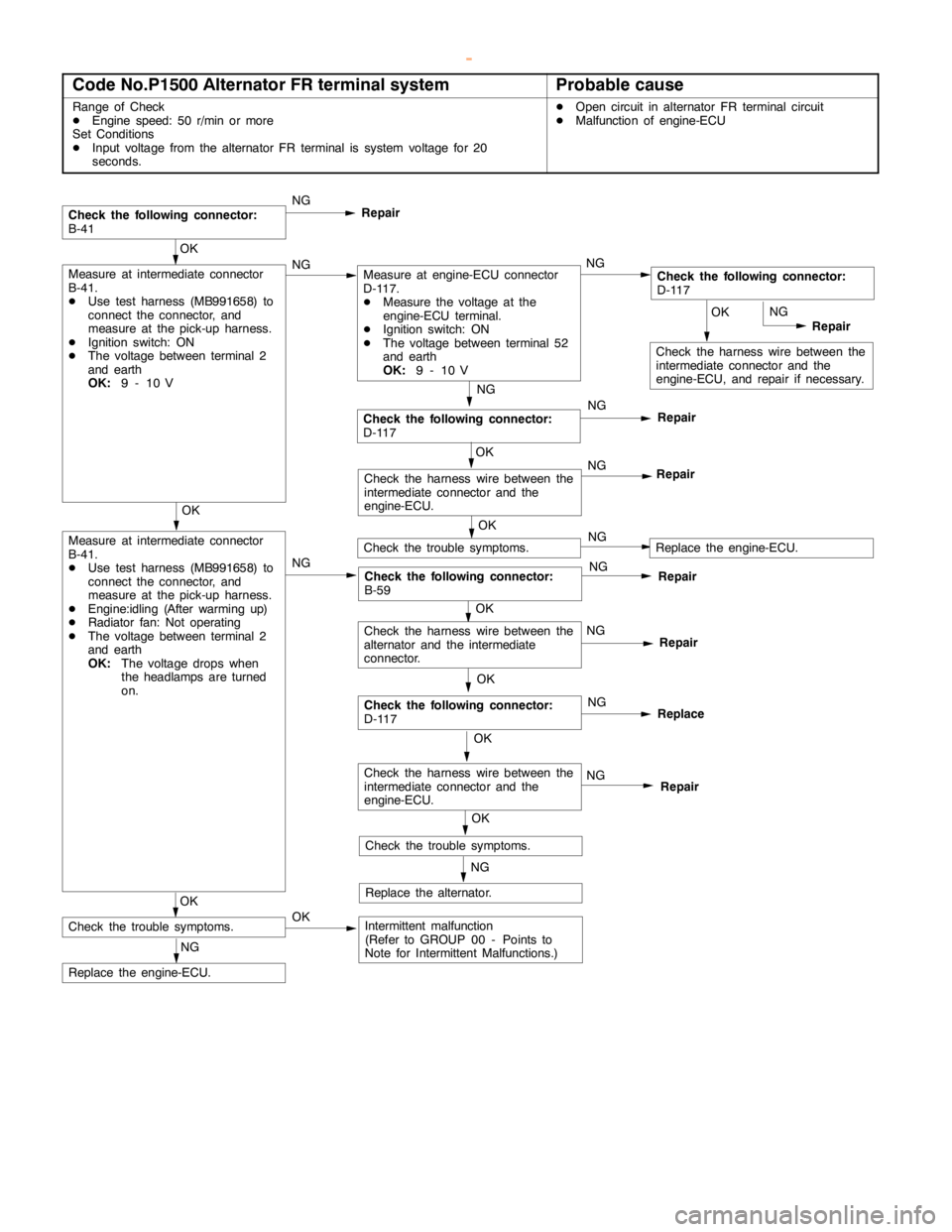
Code No.P1500 Alternator FR terminal systemProbable cause
Range of Check
DEngine speed: 50 r/min or more
Set Conditions
DInput voltage from the alternator FR terminal is system voltage for 20
seconds.DOpen circuit in alternator FR terminal circuit
DMalfunction of engine-ECU
OK
Check the harness wire between the
intermediate connector and the
engine-ECU, and repair if necessary.NG
Repair
NG
Check the following connector:
D-117NG
Repair
Check the following connector:
B-41NG
Repair
OK
Measure at intermediate connector
B-41.
DUse test harness (MB991658) to
connect the connector, and
measure at the pick-up harness.
DEngine:idling (After warming up)
DRadiator fan: Not operating
DThe voltage between terminal 2
and earth
OK:
The voltage drops when
the headlamps are turned
on.NG
Check the following connector:
B-59NG
Repair
OK
Check the trouble symptoms.
NG
Replace the engine-ECU.
OK
Check the harness wire between the
intermediate connector and the
engine-ECU.NG
Repair
OK
Measure at intermediate connector
B-41.
DUse test harness (MB991658) to
connect the connector, and
measure at the pick-up harness.
DIgnition switch: ON
DThe voltage between terminal 2
and earth
OK:
9 - 10 VNGMeasure at engine-ECU connector
D-117.
DMeasure the voltage at the
engine-ECU terminal.
DIgnition switch: ON
DThe voltage between terminal 52
and earth
OK:
9 - 10 VNGCheck the following connector:
D-117
OK
NG
Repair
OK
Check the following connector:
D-117NG
Replace
OK
Check the trouble symptoms.NGReplace the engine-ECU.
OK
Check the harness wire between the
intermediate connector and the
engine-ECU.NG
Repair
NG
Replace the alternator.OK
Check the trouble symptoms.OKIntermittent malfunction
(Refer to GROUP 00 - Points to
Note for Intermittent Malfunctions.)
Check the harness wire between the
alternator and the intermediate
connector.
www.WorkshopManuals.co.uk
Purchased from www.WorkshopManuals.co.uk
Page 286 of 1839

GDI -Troubleshooting
INSPECTION CHART FOR TROUBLE SYMPTOMS
Trouble symptomInspection
procedure
No.Reference page
CommunicationCommunication with all systems is not possible.113A-74
with MUT-IIis
impossible.
Communication with engine-ECU only is not possible.213A-75
Engine warning
lamp andThe engine warning lamp does not illuminate right after the
ignition switch is turned to the ON position.313A-76
related parts
The engine warning lamp remains illuminating and never goes
out.413A-76
StartingNo initial combustion (starting impossible)513A-77
Initial combustion but no complete combustion
(starting impossible)613A-79
Long time to start (improper starting)
Idling stabilityUnstable idling (Rough idling, hunting)713A-81
(Improper idling)
Idling speed is high. (Improper idling speed)813A-83
Idling speed is low. (Improper idling speed)
Idling stabilityWhen the engine is cold, it stalls at idling. (Die out)913A-84
(Engine stalls)
When the engine is hot, it stalls at idling. (Die out)1013A-85
The engine stalls when starting the car. (Pass out)1113A-87
The engine stalls when decelerating.1213A-88
DrivingHesitation, sag or stumble1313A-89
Poor acceleration
Surge
The feeling of impact or vibration when accelerating1413A-90
The feeling of impact or vibration when decelerating1513A-91
Knocking1613A-91
Dieseling1713A-91
Too high CO and HC concentration when idling1813A-92
Low alternator output voltage (approx. 12.3 V)1913A-94
Engine idle speed is incorrect while the A/C is on.2013A-94
A/C condenser fan is inoperative2113A-95
Clutch switch system malfunction2213A-96
GDI ECO indi-GDI ECO indicator lamp does not illuminate.2313A-96
cator lamp sys-
tem
GDI ECO indicator lamp remains illuminated and does not go off.2413A-97
www.WorkshopManuals.co.uk
Purchased from www.WorkshopManuals.co.uk
Page 308 of 1839

GDI -Troubleshooting
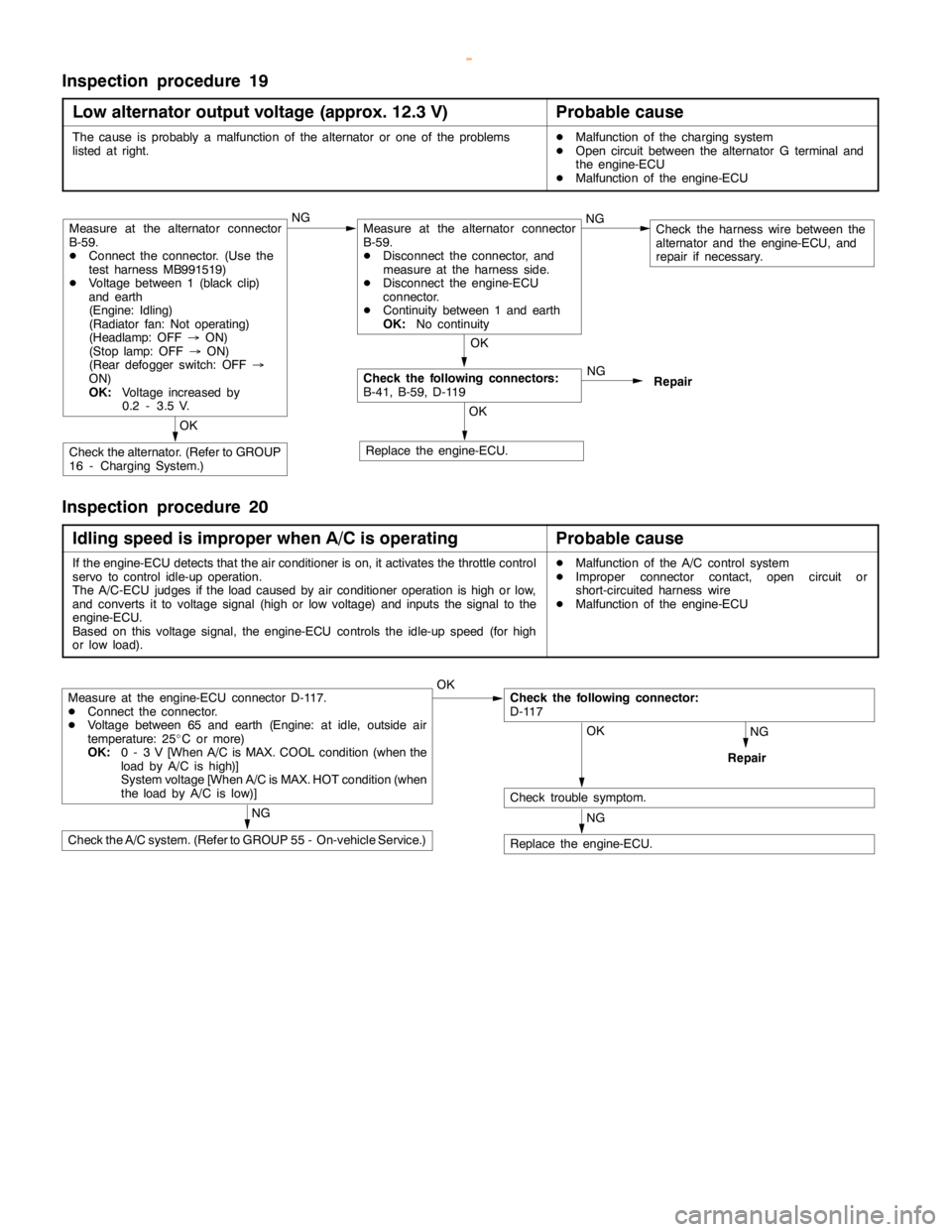
Inspection procedure 19
Low alternator output voltage (approx.12.3 V)
Probable cause
The cause is probably a malfunction of the alternator or one of the problems
listed at right.DMalfunction of the charging system
DOpen circuit between the alternator G terminal and
the engine-ECU
DMalfunction of the engine-ECU
NG
Repair
OK
Replace the engine-ECU.
OK
Check the alternator. (Refer to GROUP
16 - Charging System.)
OK
Check the following connectors:
B-41, B-59, D-119
Measure at the alternator connector
B-59.
DConnect the connector. (Use the
test harness MB991519)
DVoltage between 1 (black clip)
and earth
(Engine: Idling)
(Radiator fan: Not operating)
(Headlamp: OFF®ON)
(Stoplamp: OFF®ON)
(Rear defogger switch: OFF®
ON)
OK:
Voltage increased by
0.2 - 3.5 V.NGMeasure at the alternator connector
B-59.
DDisconnect the connector, and
measure at the harness side.
DDisconnect the engine-ECU
connector.
DContinuity between 1 and earth
OK:
No continuityNGCheck the harness wire between the
alternator and the engine-ECU, and
repair if necessary.
Inspection procedure 20
Idling speed is improper when A/C is operating
Probable cause
If the engine-ECU detects that the air conditioner is on, it activates the throttle control
servo to control idle-up operation.
The A/C-ECU judges if theloadcaused by air conditioner operation ishigh or low,
and converts it to voltage signal (high or low voltage) and inputs the signal to the
engine-ECU.
Based on this voltage signal, the engine-ECU controls the idle-up speed (forhigh
or low load).DMalfunction of the A/C control system
DImproper connector contact,opencircuit or
short-circuited harness wire
DMalfunction of the engine-ECU
NG
Repair
Measure at the engine-ECU connector D-117.
DConnect the connector.
DVoltage between 65 and earth (Engine: at idle, outside air
temperature: 25_C or more)
OK:
0 - 3 V [When A/C is MAX. COOL condition (when the
load by A/C is high)]
System voltage [When A/C is MAX. HOT condition (when
the load by A/C islow)]OKCheck the following connector:
D-117
OK
Check trouble symptom.
NG
Replace the engine-ECU.
NG
Check the A/C system. (Refer to GROUP 55 - On-vehicle Service.)
www.WorkshopManuals.co.uk
Purchased from www.WorkshopManuals.co.uk
Page 318 of 1839

GDI -Troubleshooting
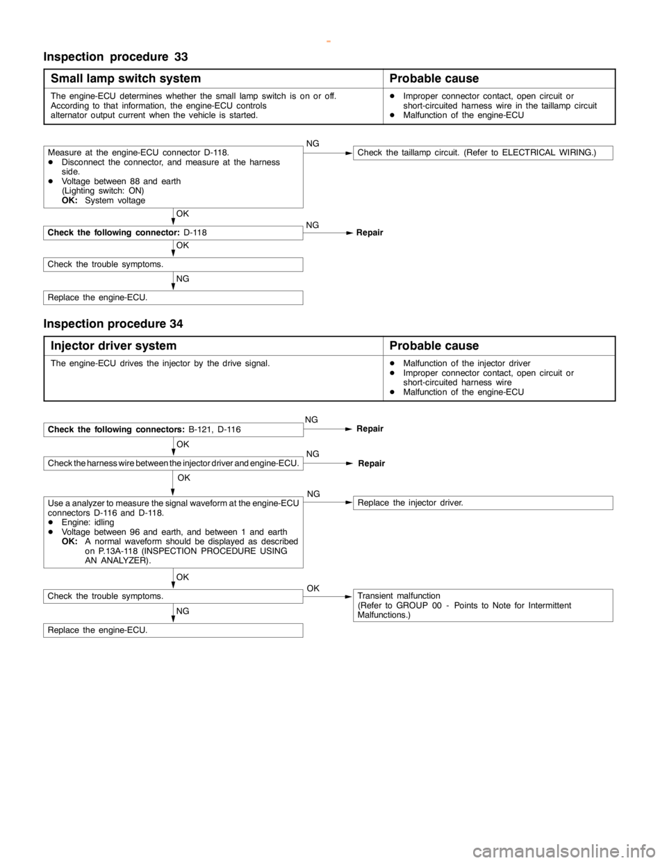
Inspection procedure 33
Small lamp switch system
Probable cause
The engine-ECU determines whether the small lampswitch is on or off.
According to that information, the engine-ECU controls
alternator output current when the vehicle is started.DImproper connector contact,opencircuit or
short-circuited harness wire in thetaillampcircuit
DMalfunction of the engine-ECU
NG
Replace the engine-ECU.
OK
Check the trouble symptoms.
OK
Check the following connector:
D-118NG
Repair
Measure at the engine-ECU connector D-118.
DDisconnect the connector, and measure at the harness
side.
DVoltage between 88 and earth
(Lighting switch: ON)
OK:
System voltageNGCheck thetaillampcircuit. (Refer to ELECTRICAL WIRING.)
Inspection procedure 34
Injector driver system
Probable cause
The engine-ECU drives the injector by the drive signal.DMalfunction of the injector driver
DImproper connector contact,opencircuit or
short-circuited harness wire
DMalfunction of the engine-ECU
OK
Check the harness wire between the injector driver and engine-ECU.
NG
Replace the engine-ECU.
OK
Check the trouble symptoms.Transient malfunction
(Refer to GROUP 00 - Points to Note for Intermittent
Malfunctions.) OK
Use a analyzer to measure the signal waveform at the engine-ECU
connectors D-116 and D-118.
DEngine: idling
DVoltage between 96 and earth, and between 1 and earth
OK:
A normal waveform should be displayed as described
on P.13A-118 (INSPECTION PROCEDURE USING
AN ANALYZER).NGReplace the injector driver.
NGCheck the following connectors:
B-121, D-116Repair
NG
Repair
OK
www.WorkshopManuals.co.uk
Purchased from www.WorkshopManuals.co.uk