2000 MITSUBISHI MONTERO display
[x] Cancel search: displayPage 7 of 1839
GENERAL -How to Use Troubleshooting/Inspection Service Points00-6
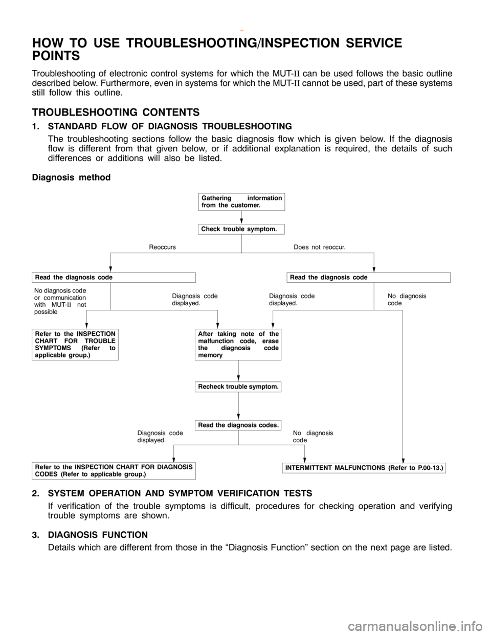
HOW TO USE TROUBLESHOOTING/INSPECTION SERVICE
POINTS
Troubleshooting of electronic control systems for which the MUT-IIcan be used follows the basic outline
described below. Furthermore, even in systems for which the MUT-IIcannot be used, part of these systems
still follow this outline.
TROUBLESHOOTING CONTENTS
1. STANDARD FLOW OF DIAGNOSIS TROUBLESHOOTING
The troubleshooting sections follow the basic diagnosis flow which is given below. If the diagnosis
flow is different from that given below, or if additional explanation is required, the details of such
differences or additions will also be listed.
Diagnosis method
Gathering information
from the customer.
Check trouble symptom.
Reoccurs Does not reoccur.
Read the diagnosis code
No diagnosis code
or communication
with MUT-
IInot
possible
Refer to the INSPECTION
CHART FOR TROUBLE
SYMPTOMS (Refer to
applicable group.)Diagnosis code
displayed.
Read the diagnosis code
Diagnosis code
displayed.No diagnosis
code
After taking note of the
malfunction code, erase
the diagnosis code
memory
Recheck trouble symptom.
Diagnosis code
displayed.
Read the diagnosis codes.
No diagnosis
code
Refer to the INSPECTION CHART FOR DIAGNOSIS
CODES (Refer to applicable group.)INTERMITTENT MALFUNCTIONS (Refer to P.00-13.)
2. SYSTEM OPERATION AND SYMPTOM VERIFICATION TESTS
If verification of the trouble symptoms is difficult, procedures for checking operation and verifying
trouble symptoms are shown.
3. DIAGNOSIS FUNCTION
Details which are different from those in the “Diagnosis Function” section on the next page are listed.
www.WorkshopManuals.co.uk
Purchased from www.WorkshopManuals.co.uk
Page 226 of 1839

GDI -Troubleshooting
FREEZE FRAME DATA
When the engine-ECU detects a malfunction and stores a
diagnosis code, it also stores a current status of the engine.
This function is called “Freeze frame data.” By analyzing
this “freeze frame” data with the MUT-II, an effective
troubleshooting can be performed.
Data itemUnit
Engine coolant temperature sensor_C
Engine speedr/min
Vehicle speedkm/h
Long-term fuel compensation (long-term
fuel trim)%
Short-term fuel compensation (short-term
fuel trim)%
Fuel control condi-Open loopOL
tion
Closed loopCL
Open loop owing to
drive conditionOL-DRV.
Open loop owing to
system malfunctionOL-SYS.
Closed loop based
on one oxygen sen-
sorCL-H02S
Calculation load value%
Diagnosis code during data recording-
NOTE
If malfunctions have been detected in multiple systems, store
one malfunction only, which has been detected first.
READINESS TEST STATUS
The engine-ECU monitors the following main diagnosis items,
judges if these items are in good condition or not, and the
stores its history. This history can be read out by using MUT-II.
(If the ECU has judged a item before, the MUT-II displays
“Complete.”)
In addition, if diagnosis codes are erased or the battery
cable is disconnected, this history will also be erased (the
memory will be reset).
DCatalyst: P0420
DOxygen sensor: P0130
DOxygen sensor heater: P0135, P0141
www.WorkshopManuals.co.uk
Purchased from www.WorkshopManuals.co.uk
Page 232 of 1839
GDI -Troubleshooting
OK
Check the harness between the air
flow sensor and the engine-ECU.NG
Repair
OK
Check the harnesses between the
air flow sensor and the engine-ECU
and between the air flow sensor and
the engine controlrelay, and repair if
necessary.
From the previouspage
OK
Measure at air flow sensor connector
B-120.
DUse test harness (MB991709) to
connect the connector, and
measure at the pick-up harness.
DSelector lever position: P
DVoltage between terminal 7 and
earth
OK:
Engine: Idling
0-1V
Engine speed: 3000 r/min
6-9VNGCheck the following connector:
D-118NGRepair
OK
Check the trouble symptoms.
NG
Replace the engine-ECU.
Check the trouble symptoms.
NG
Check the following connectors:
B-25X, D-117, D-118NG
Repair
OK
Measure the output wave form at air
flow sensor connector B-120 (by
using an analyzer).
DUse test harness (MB991709) to
connect the connector, and
measure at the pick-up harness.
DEngine: Idling
DVoltage between terminal 3 and
earth
OK:
Waveforms should be dis-
played on P.13A-118 (In-
spection Procedure Using
an Analyzer) and noise
should not be displayed in
the waveform.NGReplace the air flow sensor.
OK
Check the trouble symptoms.
NG
Replace the engine-ECU.OK
www.WorkshopManuals.co.uk
Purchased from www.WorkshopManuals.co.uk
Page 252 of 1839
GDI -Troubleshooting
Code No.P0201 No.1 injector systemProbable cause
Range of Check
DThe enginespeed is 4,000 r/min or less.
DThe battery voltage is 10 V or more.
DThe fuel cut operation or the injector operation (by carrying out the Actuator
Test) is not in progress.
Set Conditions
DThe injector driver is not transmitting a injectoropencircuit check signal for
four seconds.DMalfunction of No.1 injector
DOpen or short circuit in the No.1 injector circuit or
loose connector contact
DMalfunction of engine-ECU
NG
Check the following connector:
B-105NG
Repair
OK
NG
Repair
MUT-
IIActuator Test
01 No.1 injector
OK:
The idling condition should
change.OKCheck the trouble symptoms.OKTransient malfunction
(Refer to GROUP 00 - Points to
Note for Intermittent Malfunctions.)
NG
Replace the injector driver.
Check the trouble symptoms.NGReplace the engine-ECU.
OK
Measure at intermediate connector
B-105.
DDisconnect the connector and
measure at the harness side.
DResistance between terminals 11
and 12
OK:
0.9 - 1.1WNGCheck the following connector:
B-117NG
Repair
OK
Replace the No.1 injector.
OK
Check the following connector:
B-121NG
Repair
OK
Check the harness wire between the
injector driver and the intermediate
connector.NG
Repair
OK
Check the following connector:
D-116NG
Repair
OK
Check the harness wire between the
injector driver and the engine-ECU.NG
Repair
OK
Use an analyzer to measure the
signal waveform at engine-ECU
connectors D-116 and D-118.
DEngine: Idling
DVoltage between terminal 1 and
earth
OK:
A normal waveform should
be displayed as described
on P.13A-121 (INSPEC-
TION PROCEDURE US-
ING AN ANALYZER).NGCheck the following connector:
B-117
OK
Check the following connector:
B-117NG
Repair
OK
To the nextpageNG
OK
OK
Check the harness wire between the
No.1 injector and the intermediate
connector.NG
Replace the engine-ECU.
Repair
Repair
Check the harness wire between
No.1 injector and the intermediate
connector.
www.WorkshopManuals.co.uk
Purchased from www.WorkshopManuals.co.uk
Page 254 of 1839
GDI -Troubleshooting
Code No.P0202 No.2 injector systemProbable cause
Range of Check
DThe enginespeed is 4,000 r/min or less.
DThe battery voltage is 10 V or more.
DThe fuel cut operation or the injector operation (by carrying out the Actuator
Test) is not in progress.
Set Conditions
DThe injector driver is not transmitting a injectoropencircuit check signal for
four seconds.DMalfunction of No.2 injector
DOpen or short circuit in the No.2 injector circuit or
loose connector contact
DMalfunction of engine-ECU
NG
Check the following connector:
B-105NG
Repair
OK
NG
Repair
MUT-
IIActuator Test
02 No.2 injector
OK:
The idling condition should
change.OKCheck the trouble symptoms.OKTransient malfunction
(Refer to GROUP 00 - Points to
Note for Intermittent Malfunctions.)
NG
Replace the injector driver.
Check the trouble symptoms.NGReplace the engine-ECU.
OK
Measure at intermediate connector
B-105.
DDisconnect the connector and
measure at the harness side.
DResistance between terminals 5
and 6
OK:
0.9 - 1.1WNGCheck the following connector:
B-114NG
Repair
OK
Replace the No.2 injector.
OK
Check the following connector:
B-121NG
Repair
OK
Check the harness wire between the
injector driver and the intermediate
connector.NG
Repair
OK
Check the following connector:
D-116NG
Repair
OK
Check the harness wire between the
injector driver and the engine-ECU.NG
Repair
OK
Use an analyzer to measure the
signal waveform at engine-ECU
connectors D-116 and D-118.
DEngine: Idling
DVoltage between terminal 9 and
earth
OK:
A normal waveform should
be displayed as described
on P.13A-121 (INSPEC-
TION PROCEDURE US-
ING AN ANALYZER).NGCheck the following connector:
B-114
OK
Check the following connector:
B-114NG
Repair
OK
To the nextpageNG
OK
OK
Check the harness wire between the
No.2 injector and the intermediate
connector.NG
Replace the engine-ECU.
Repair
Repair
Check the harness wire between
No.2 injector and the intermediate
connector.
www.WorkshopManuals.co.uk
Purchased from www.WorkshopManuals.co.uk
Page 256 of 1839
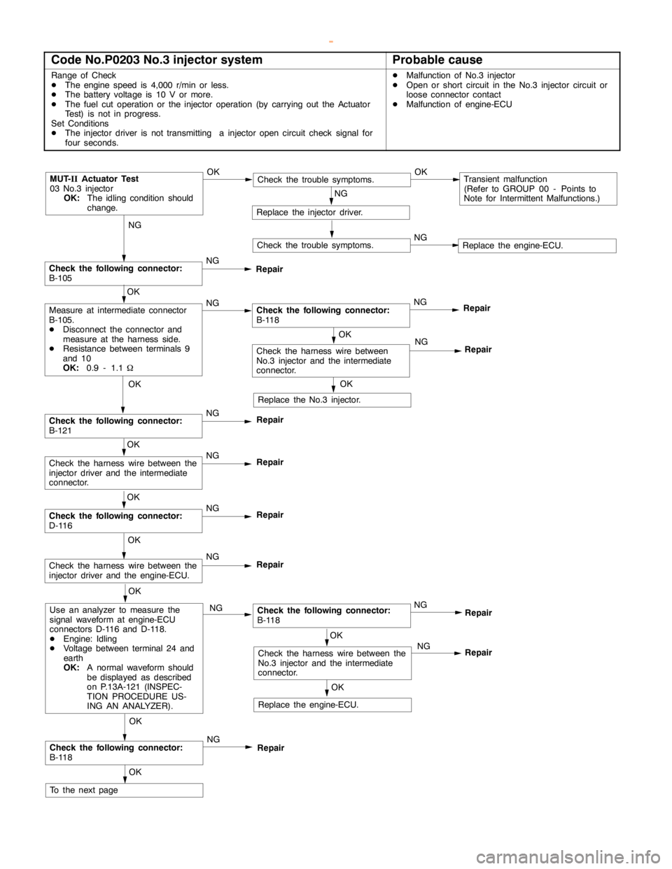
GDI -Troubleshooting
Code No.P0203 No.3 injector systemProbable cause
Range of Check
DThe enginespeed is 4,000 r/min or less.
DThe battery voltage is 10 V or more.
DThe fuel cut operation or the injector operation (by carrying out the Actuator
Test) is not in progress.
Set Conditions
DThe injector driver is not transmitting a injectoropencircuit check signal for
four seconds.DMalfunction of No.3 injector
DOpen or short circuit in the No.3 injector circuit or
loose connector contact
DMalfunction of engine-ECU
NG
Check the following connector:
B-105NG
Repair
OK
NG
Repair
MUT-
IIActuator Test
03 No.3 injector
OK:
The idling condition should
change.OKCheck the trouble symptoms.OKTransient malfunction
(Refer to GROUP 00 - Points to
Note for Intermittent Malfunctions.)
NG
Replace the injector driver.
Check the trouble symptoms.NGReplace the engine-ECU.
OK
Measure at intermediate connector
B-105.
DDisconnect the connector and
measure at the harness side.
DResistance between terminals 9
and 10
OK:
0.9 - 1.1WNGCheck the following connector:
B-118NG
Repair
OK
Replace the No.3 injector.
OK
Check the following connector:
B-121NG
Repair
OK
Check the harness wire between the
injector driver and the intermediate
connector.NG
Repair
OK
Check the following connector:
D-116NG
Repair
OK
Check the harness wire between the
injector driver and the engine-ECU.NG
Repair
OK
Use an analyzer to measure the
signal waveform at engine-ECU
connectors D-116 and D-118.
DEngine: Idling
DVoltage between terminal 24 and
earth
OK:
A normal waveform should
be displayed as described
on P.13A-121 (INSPEC-
TION PROCEDURE US-
ING AN ANALYZER).NGCheck the following connector:
B-118
OK
Check the following connector:
B-118NG
Repair
OK
To the nextpageNG
OK
OK
Check the harness wire between the
No.3 injector and the intermediate
connector.NG
Replace the engine-ECU.
Repair
Repair
Check the harness wire between
No.3 injector and the intermediate
connector.
www.WorkshopManuals.co.uk
Purchased from www.WorkshopManuals.co.uk
Page 258 of 1839
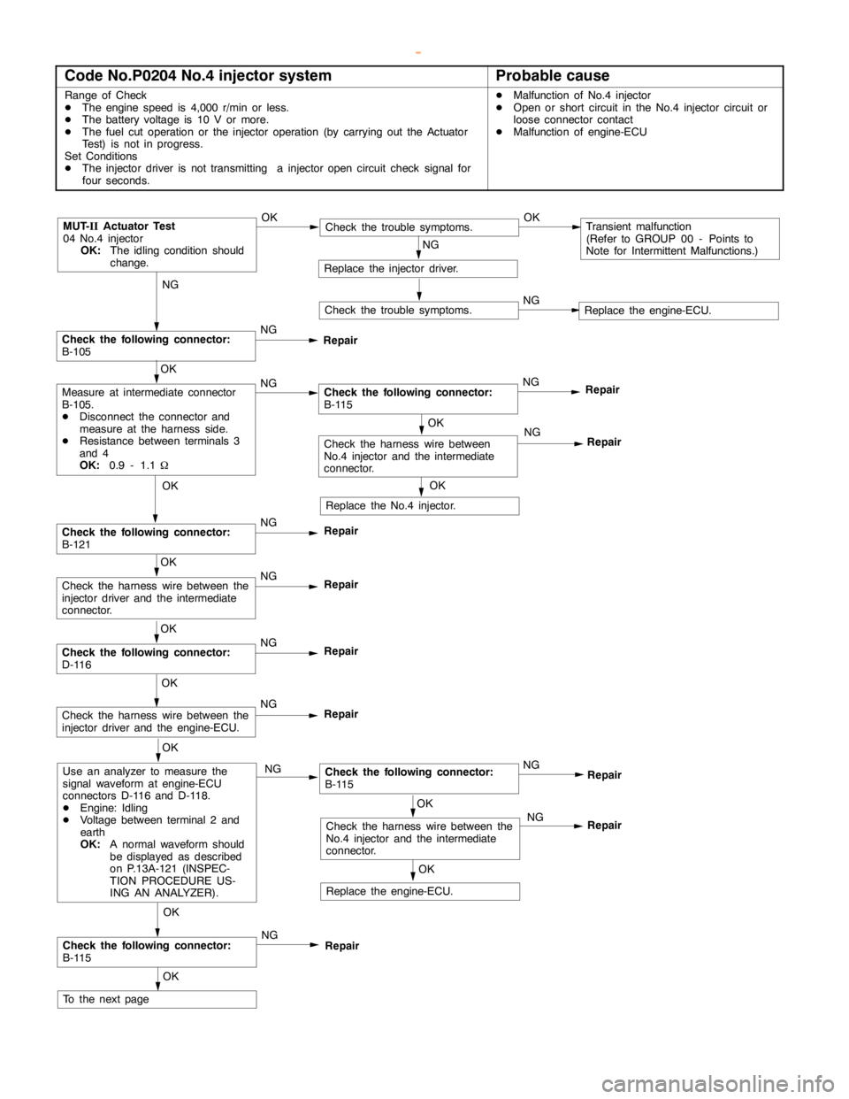
GDI -Troubleshooting
Code No.P0204 No.4 injector systemProbable cause
Range of Check
DThe enginespeed is 4,000 r/min or less.
DThe battery voltage is 10 V or more.
DThe fuel cut operation or the injector operation (by carrying out the Actuator
Test) is not in progress.
Set Conditions
DThe injector driver is not transmitting a injectoropencircuit check signal for
four seconds.DMalfunction of No.4 injector
DOpen or short circuit in the No.4 injector circuit or
loose connector contact
DMalfunction of engine-ECU
NG
Check the following connector:
B-105NG
Repair
OK
NG
Repair
MUT-
IIActuator Test
04 No.4 injector
OK:
The idling condition should
change.OKCheck the trouble symptoms.OKTransient malfunction
(Refer to GROUP 00 - Points to
Note for Intermittent Malfunctions.)
NG
Replace the injector driver.
Check the trouble symptoms.NGReplace the engine-ECU.
OK
Measure at intermediate connector
B-105.
DDisconnect the connector and
measure at the harness side.
DResistance between terminals 3
and 4
OK:
0.9 - 1.1WNGCheck the following connector:
B-115NG
Repair
OK
Replace the No.4 injector.
OK
Check the following connector:
B-121NG
Repair
OK
Check the harness wire between the
injector driver and the intermediate
connector.NG
Repair
OK
Check the following connector:
D-116NG
Repair
OK
Check the harness wire between the
injector driver and the engine-ECU.NG
Repair
OK
Use an analyzer to measure the
signal waveform at engine-ECU
connectors D-116 and D-118.
DEngine: Idling
DVoltage between terminal 2 and
earth
OK:
A normal waveform should
be displayed as described
on P.13A-121 (INSPEC-
TION PROCEDURE US-
ING AN ANALYZER).NGCheck the following connector:
B-115
OK
Check the following connector:
B-115NG
Repair
OK
To the nextpageNG
OK
OK
Check the harness wire between the
No.4 injector and the intermediate
connector.NG
Replace the engine-ECU.
Repair
Repair
Check the harness wire between
No.4 injector and the intermediate
connector.
www.WorkshopManuals.co.uk
Purchased from www.WorkshopManuals.co.uk
Page 260 of 1839
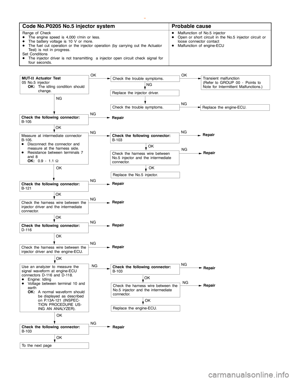
GDI -Troubleshooting
Code No.P0205 No.5 injector systemProbable cause
Range of Check
DThe enginespeed is 4,000 r/min or less.
DThe battery voltage is 10 V or more.
DThe fuel cut operation or the injector operation (by carrying out the Actuator
Test) is not in progress.
Set Conditions
DThe injector driver is not transmitting a injectoropencircuit check signal for
four seconds.DMalfunction of No.5 injector
DOpen or short circuit in the No.5 injector circuit or
loose connector contact
DMalfunction of engine-ECU
NG
Check the following connector:
B-105NG
Repair
OK
NG
Repair
MUT-
IIActuator Test
05 No.5 injector
OK:
The idling condition should
change.OKCheck the trouble symptoms.OKTransient malfunction
(Refer to GROUP 00 - Points to
Note for Intermittent Malfunctions.)
NG
Replace the injector driver.
Check the trouble symptoms.NGReplace the engine-ECU.
OK
Measure at intermediate connector
B-105.
DDisconnect the connector and
measure at the harness side.
DResistance between terminals 7
and 8
OK:
0.9 - 1.1WNGCheck the following connector:
B-103NG
Repair
OK
Replace the No.5 injector.
OK
Check the following connector:
B-121NG
Repair
OK
Check the harness wire between the
injector driver and the intermediate
connector.NG
Repair
OK
Check the following connector:
D-116NG
Repair
OK
Check the harness wire between the
injector driver and the engine-ECU.NG
Repair
OK
Use an analyzer to measure the
signal waveform at engine-ECU
connectors D-116 and D-118.
DEngine: Idling
DVoltage between terminal 10 and
earth
OK:
A normal waveform should
be displayed as described
on P.13A-121 (INSPEC-
TION PROCEDURE US-
ING AN ANALYZER).NGCheck the following connector:
B-103
OK
Check the following connector:
B-103NG
Repair
OK
To the nextpageNG
OK
OK
Check the harness wire between the
No.5 injector and the intermediate
connector.NG
Replace the engine-ECU.
Repair
Repair
Check the harness wire between
No.5 injector and the intermediate
connector.
www.WorkshopManuals.co.uk
Purchased from www.WorkshopManuals.co.uk