2000 MITSUBISHI MONTERO air conditioning
[x] Cancel search: air conditioningPage 217 of 1839

GDI -General Information13A-3
GENERAL INFORMATION
The Gasoline Direct Injection System consists
of sensors which detect the engine conditions,
the engine-ECU
which controls the system based on
signals from these sensors, and actuators
which operate under the control of the
engine-ECU
carries out activities such as fuel injection
control, idle speed control and ignition timing
control. In addition, the engine-ECU
engine-A/T-ECU is equipped with several
diagnosis modes which simplify troubleshooting
when a problem develops.
FUEL INJECTION CONTROL
The injector drive times and injector timing are
controlled so that the optimum air/fuel mixture
is supplied to the engine to correspond to the
continually-changing engine operation condi-
tions.
A single injector for each cylinder is mounted
at the cylinder head. The fuel is sent under
pressure from the fuel tank to the fuel pressure
regulator (low pressure) by the fuel pump (low
pressure). The pressure is regulated by the
fuel pressure regulator (low pressure) and the
fuel regulated is then sent to the fuel pump
(high pressure). The fuel under increased
pressure generated by the fuel pump (high
pressure) is then regulated by the fuel pressure
regulator (high pressure) and is then distributed
to each of the injectors via the delivery pipes.Fuel injection is normally carried out once for
each cylinder for every two rotations of the
crankshaft. The firing order is 1-2-3-4-5-6. This
is called sequential fuel injection.
When the engine is cold or under a severe
load, the “open-loop” control keeps the air/fuel
ratio at a richer than usual level to maintain
driveability. When the engine is under low or
medium loads, the air/fuel ratio becomes leaner
to reduce fuel consumption. When the engine
is running at medium or high loads after having
warmed up, the “closed-loop” control uses the
signal from the oxygen sensor to keep the
air/fuel ratio at the optimum theoretical level.
THROTTLE VALVE OPENING ANGLE CONTROL
This system controls throttle valve opening
angle electronically. The engine-ECU
or engine-A/T-ECU determines how
deeply the accelerator pedal is depressed by
means of the accelerator position sensor (APS).
Then the engine-ECU
throttle valve opening angle to the throttle valve
controller. The throttle valve control servo
operates the throttle valve so that it reaches
the target opening angle.
IDLE SPEED CONTROL
This system maintains engine idle speed at
a predetermined condition by controlling the
air flow that passes through the throttle valve
according to engine idling condition and engine
loads at idling.
The engine-ECU
operates the throttle valve control servoso that engine speed is maintained within a
map value. The map value is predetermined
according to engine coolant temperature and
air-conditioning load.
IGNITION TIMING CONTROL
The power transistor located in the ignition
primary circuit turns ON and OFF to control
the primary current flow to the ignition coil. This
controls the ignition timing in order to provide
the optimum ignition timing with respect to the
engine operating conditions. The ignition timingis determined by the engine-ECU
engine-A/T-ECU from the engine speed,
intake air volume, engine coolant temperature,
atmospheric pressure and injection timing
(intake stroke or compression stroke).
www.WorkshopManuals.co.uk
Purchased from www.WorkshopManuals.co.uk
Page 1631 of 1839

CHASSIS ELECTRICAL -Clock or Center Display54A-61
INSPECTION CHART CLASSIFIED BY TROUBLE SYMPTOMS
Related unitTrouble SymptomInspection pro-
cedure No.Reference
page
Malfunction of center
display, related sen-No display appears after the ignition key is turned to the
ACC position.154A-62
sors, and wiring har-
nesses
Outside air temperature does not appear or abnormal
outside air temperature appears.254A-62
Abnormal vehicle speed is displayed on the service
mode.354A-63
Abnormal driving data are displayed:
D
Abnormal average fuel consumption (momentary
fuel consumption) and average vehicle speed
D
Abnormal cruising distance454A-64
Clock runs fast or slow.554A-64
The display screen is dim.654A-65
Air conditioning display does not apper.754A-66
www.WorkshopManuals.co.uk
Purchased from www.WorkshopManuals.co.uk
Page 1632 of 1839

CHASSIS ELECTRICAL -Clock or Center Display54A-62
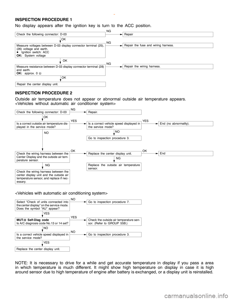
INSPECTION PROCEDURE 1
No display appears after the ignition key is turn to the ACC position.
OK
Measure voltages between D-03 display connector terminal (25),
(26) voltage and earth.
DIgnition switch: ACC
OK:System voltageNGRepair the fuse and wiring harness.
OK
Measure resistance between D-03 display connector terminal (28)
and earth.
OK:approx. 0
WNGRepair the wiring harness.
OK
Repair the center display unit.
Check the following connector: D-03NGRepair
INSPECTION PROCEDURE 2
Outside air temperature does not appear or abnormal outside air temperature appears.
Check the following connector: D-03NGRepair.
NO
Go to inspection procedure 3.
Check the wiring harness between the
Center Display and the outside air tem-
perature sensor.OKReplace the center display unit.OKEnd
NG
Replace the outside air temperature
sensor.NG
Check the wiring harness between the
center display unit and the outside air
temperature sensor, and replace if nec-
essary.
OK
Is a correct outside air temperature dis-
played in the servicemode?YESIs a correct vehicle speed displayed in
the servicemode?YESEnd (no abnormality).
NO
Select “Check of units connected into
the center display” on the service mode.
Does the symbol “AU” appear?NOGo to inspection procedure 7.
YES
Replace the center display unit.
YES
MUT-
IISelf-Diag code
Is A/C diagnosis code No.13 or 14 set?YESCheck the outside air temperature sen-
sor. (Refer to GROUP 55B.)
NO
Is a correct vehicle speed displayed in
the servicemode?NOGo to inspection procedure 3.
NOTE: It is necessary to drive for a while and get accurate temperature in display if you pass a area
in which temperature is much different. It might show high temperature on display in case it is high
around sensor due to high temperature of engine after battery is exchanged, or a display unit is reinstalled.
www.WorkshopManuals.co.uk
Purchased from www.WorkshopManuals.co.uk
Page 1636 of 1839

CHASSIS ELECTRICAL -Clock or Center Display54A-66
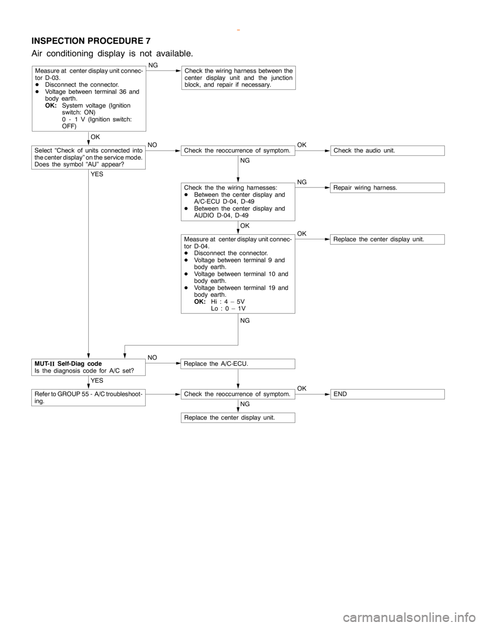
INSPECTION PROCEDURE 7
Air conditioning display is not available.
Measure at center display unit connec-
tor D-03.
DDisconnect the connector.
DVoltage between terminal 36 and
body earth.
OK:System voltage (Ignition
switch: ON)
0 - 1 V (Ignition switch:
OFF)NGCheck the wiring harness between the
center display unit and the junction
block, and repair if necessary.
OK
NO OK
Check theaudio unit.
NG
NG
Repair wiring harness.
OK
OK
Replace the center display unit.
YES
Replace the A/C-ECU.
YES
Refer to GROUP 55 - A/C troubleshoot-
ing.Check the reoccurrence of symptom.OKEND
NG
Replace the center display unit.
Measure at center display unit connec-
tor D-04.
DDisconnect the connector.
DVoltage between terminal 9 and
body earth.
DVoltage between terminal 10 and
body earth.
DVoltage between terminal 19 and
body earth.
OK:Hi:4–5V
Lo:0–1V
Check the the wiring harnesses:
DBetween the center display and
A/C-ECU D-04, D-49
DBetween the center display and
AUDIO D-04, D-49
Check the reoccurrence of symptom.Select “Check of units connected into
the center display” on the service mode.
Does the symbol “AU” appear?
MUT-
IISelf-Diag code
Is the diagnosis code for A/C set?NG
NO
www.WorkshopManuals.co.uk
Purchased from www.WorkshopManuals.co.uk