2000 MITSUBISHI MONTERO check engine light
[x] Cancel search: check engine lightPage 264 of 1839
GDI -Troubleshooting
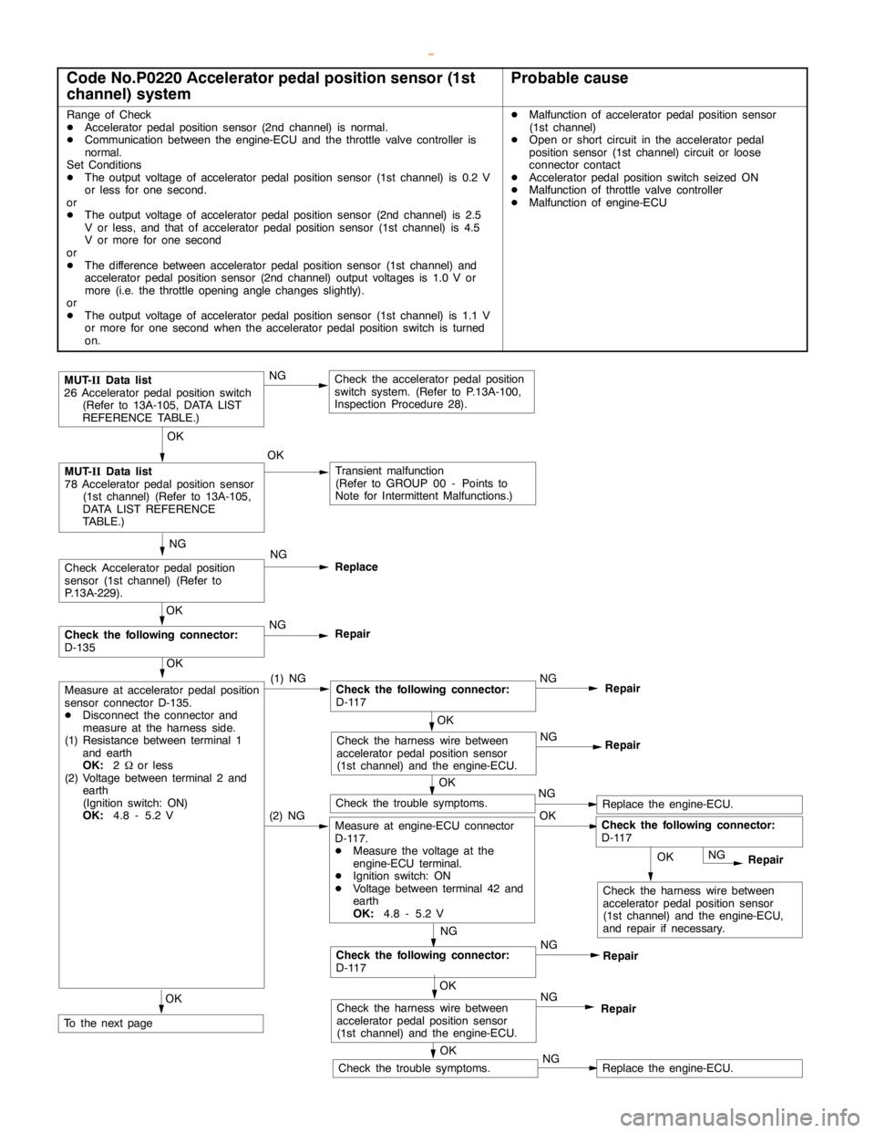
Code No.P0220 Accelerator pedal position sensor (1st
channel) systemProbable cause
Range of Check
DAcceleratorpedal positionsensor (2nd channel) is normal.
DCommunication between the engine-ECU and the throttle valve controller is
normal.
Set Conditions
DThe output voltage of accelerator pedal positionsensor (1st channel) is 0.2 V
or less for one second.
or
DThe output voltage of accelerator pedal positionsensor (2nd channel) is 2.5
V or less, and that of acceleratorpedal positionsensor (1st channel) is 4.5
V or more for one second
or
DThe difference between accelerator pedal positionsensor (1st channel) and
accelerator pedal positionsensor (2nd channel) output voltages is 1.0 V or
more (i.e. the throttle opening anglechanges slightly).
or
DThe output voltage of accelerator pedal positionsensor (1st channel) is 1.1 V
or more for one second when the acceleratorpedal positionswitch is turned
on.DMalfunction of accelerator pedal positionsensor
(1st channel)
DOpen or short circuit in the acceleratorpedal
position sensor (1st channel) circuit or loose
connector contact
DAcceleratorpedal positionswitch seized ON
DMalfunction of throttle valve controller
DMalfunction of engine-ECU
OK
Check the harness wire between
accelerator pedal positionsensor
(1st channel) and the engine-ECU,
and repair if necessary.
NG
Check Acceleratorpedal position
sensor (1st channel) (Refer to
P.13A-229).NG
Replace
OK
Check the trouble symptoms.NGReplace the engine-ECU.(2) NGMeasure at engine-ECU connector
D-117.
DMeasure the voltage at the
engine-ECU terminal.
DIgnition switch: ON
DVoltage between terminal 42 and
earth
OK:
4.8 - 5.2 VOK
OK
MUT-
IIData list
78 Acceleratorpedal positionsensor
(1st channel) (Refer to 13A-105,
DATA LIST REFERENCE
TABLE.)OKTransient malfunction
(Refer to GROUP 00 - Points to
Note for Intermittent Malfunctions.)
OK
Check the trouble symptoms.NGReplace the engine-ECU.
MUT-
IIData list
26 Acceleratorpedal positionswitch
(Refer to 13A-105, DATA LIST
REFERENCE TABLE.)NGCheck the acceleratorpedal position
switch system. (Refer to P.13A-100,
Inspection Procedure 28).
OK
Measure at accelerator pedal position
sensor connector D-135.
DDisconnect the connector and
measure at the harness side.
(1) Resistance between terminal 1
and earth
OK:
2Wor less
(2) Voltage between terminal 2 and
earth
(Ignition switch: ON)
OK:
4.8 - 5.2 V(1) NGCheck the following connector:
D-117NGRepair
NG
Repair
NG
Check the following connector:
D-117NG
Repair
OK
Check the following connector:
D-135NG
Repair
OK
Check the harness wire between
accelerator pedal positionsensor
(1st channel) and the engine-ECU.NG
Repair
OK
Check the harness wire between
accelerator pedal positionsensor
(1st channel) and the engine-ECU.NG
RepairOK
To the nextpage
Check the following connector:
D-117
OK
www.WorkshopManuals.co.uk
Purchased from www.WorkshopManuals.co.uk
Page 282 of 1839
GDI -Troubleshooting
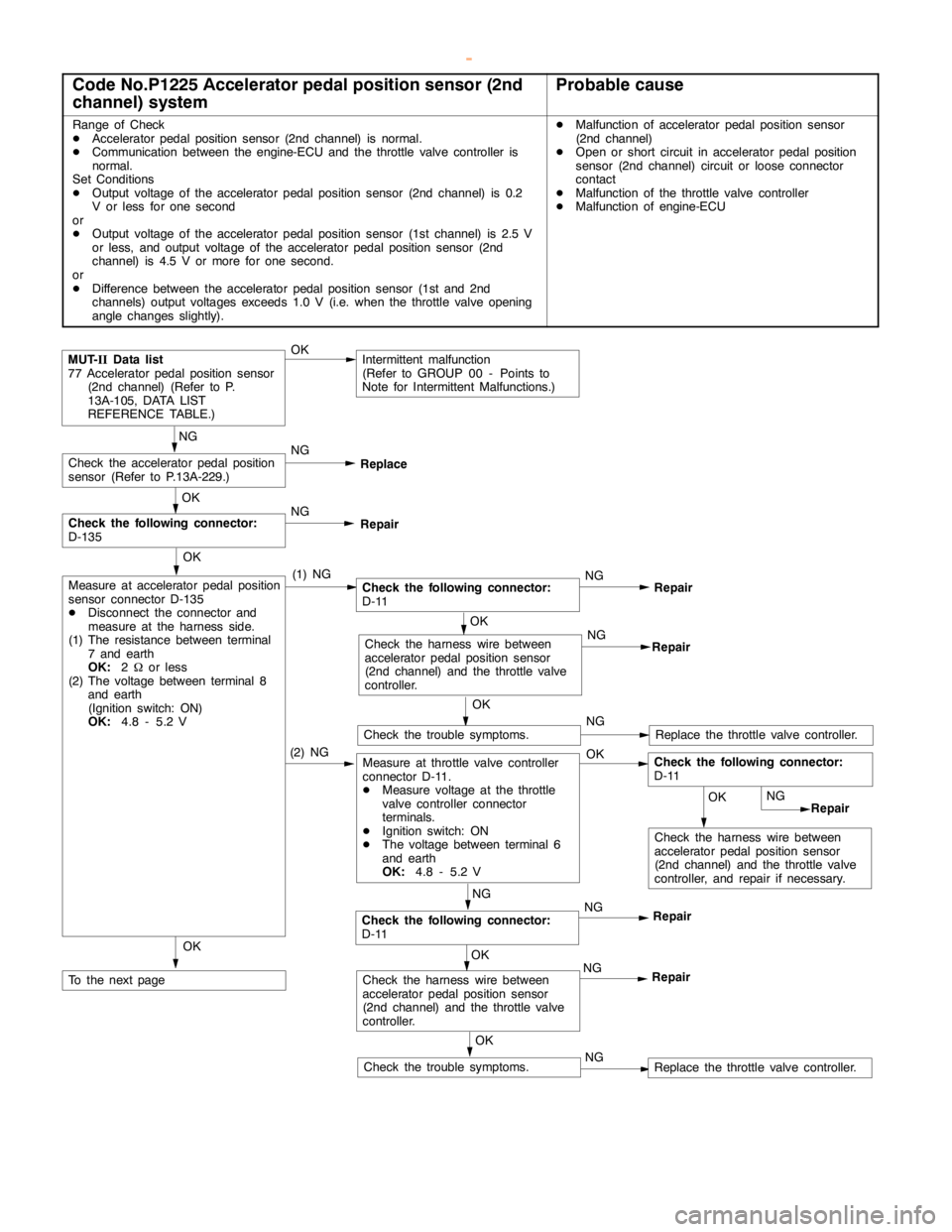
Code No.P1225 Accelerator pedal position sensor (2nd
channel) systemProbable cause
Range of Check
DAcceleratorpedal positionsensor (2nd channel) is normal.
DCommunication between the engine-ECU and the throttle valve controller is
normal.
Set Conditions
DOutput voltage of the accelerator pedal positionsensor (2nd channel) is 0.2
V or less for one second
or
DOutput voltage of the accelerator pedal positionsensor (1st channel) is 2.5 V
or less, and output voltage of the acceleratorpedal positionsensor (2nd
channel) is 4.5 V or more for one second.
or
DDifference between the accelerator pedal positionsensor (1st and 2nd
channels) output voltages exceeds 1.0 V (i.e. when the throttle valveopening
anglechanges slightly).DMalfunction of accelerator pedal positionsensor
(2nd channel)
DOpen or short circuit in acceleratorpedal position
sensor (2nd channel) circuit or loose connector
contact
DMalfunction of the throttle valve controller
DMalfunction of engine-ECU
OKIntermittent malfunction
(Refer to GROUP 00 - Points to
Note for Intermittent Malfunctions.)
NG
Check the acceleratorpedal position
sensor (Refer to P.13A-229.)NG
Replace
OK
Measure at accelerator pedal position
sensor connector D-135
DDisconnect the connector and
measure at the harness side.
(1) The resistance between terminal
7 and earth
OK:
2Wor less
(2) The voltage between terminal 8
and earth
(Ignition switch: ON)
OK:
4.8 - 5.2 V(1) NGCheck the following connector:
D-11NG
Repair
OK
Check the following connector:
D-135NG
Repair
Check the harness wire between
accelerator pedal positionsensor
(2nd channel) and the throttle valve
controller.NG
Repair
OK
Check the trouble symptoms.NGReplace the throttle valve controller.
(2) NGMeasure at throttle valve controller
connector D-11.
DMeasure voltage at the throttle
valve controller connector
terminals.
DIgnition switch: ON
DThe voltage between terminal 6
and earth
OK:
4.8 - 5.2 VOK
OK
Check the harness wire between
accelerator pedal positionsensor
(2nd channel) and the throttle valve
controller, and repair if necessary.NG
Repair
NG
Check the following connector:
D-11NG
Repair
OK
Check the harness wire between
accelerator pedal positionsensor
(2nd channel) and the throttle valve
controller.NG
Repair
OK
To the nextpage
OK
Check the trouble symptoms.NGReplace the throttle valve controller. OK
MUT-
IIData list
77 Acceleratorpedal positionsensor
(2nd channel) (Refer to P.
13A-105, DATA LIST
REFERENCE TABLE.)
Check the following connector:
D-11
www.WorkshopManuals.co.uk
Purchased from www.WorkshopManuals.co.uk
Page 291 of 1839
GDI -Troubleshooting
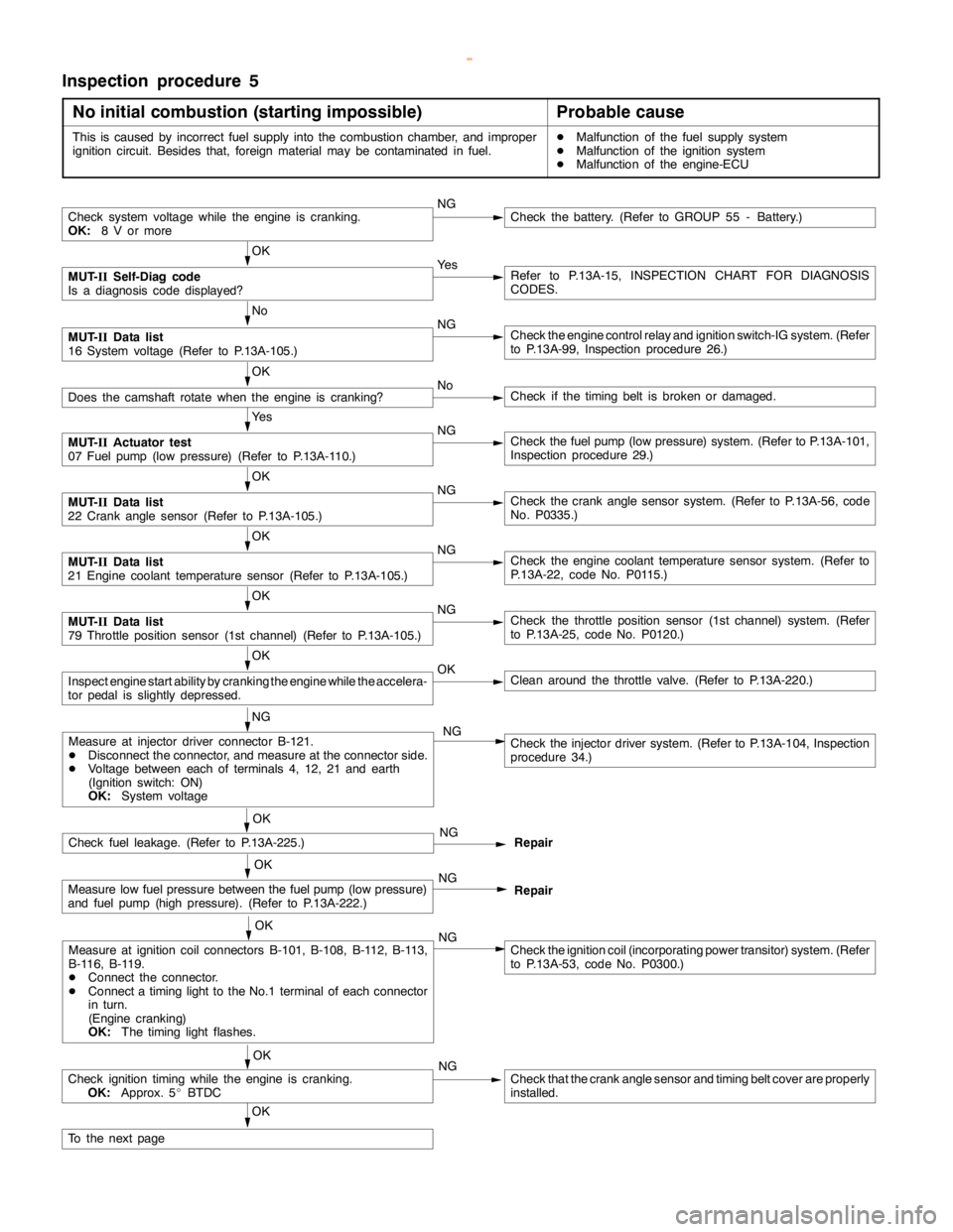
Inspection procedure 5
No initial combustion (starting impossible)
Probable cause
This is caused by incorrect fuel supply into the combustion chamber, and improper
ignition circuit. Besides that, foreign material may be contaminated in fuel.DMalfunction of the fuel supply system
DMalfunction of the ignition system
DMalfunction of the engine-ECU
Check system voltage while theengine iscranking.
OK:
8 V or moreNGCheck the battery. (Refer to GROUP 55 - Battery.)
OK
MUT-
IISelf-Diag code
Is a diagnosis code displayed?Ye sRefer to P.13A-15, INSPECTION CHART FOR DIAGNOSIS
CODES.
No
MUT-
IIData list
16 System voltage (Refer to P.13A-105.)NGCheck theengine controlrelay and ignition switch-IG system. (Refer
to P.13A-99, Inspection procedure 26.)
OK
Does the camshaft rotate when theengine is cranking?NoCheck if thetiming belt isbroken ordamaged.
Ye s
MUT-
IIActuator test
07 Fuel pump(low pressure) (Refer to P.13A-110.)NGCheck the fuelpump(low pressure) system. (Refer to P.13A-101,
Inspection procedure 29.)
OK
MUT-
IIData list
22 Crankanglesensor (Refer to P.13A-105.)NGCheck the crankanglesensor system. (Refer to P.13A-56, code
No. P0335.)
OK
MUT-
IIData list
21 Engine coolant temperature sensor (Refer to P.13A-105.)NGCheck theengine coolant temperaturesensor system. (Refer to
P.13A-22, code No. P0115.)
OK
MUT-
IIData list
79 Throttle position sensor (1st channel) (Refer to P.13A-105.)NGCheck the throttle position sensor (1st channel) system. (Refer
to P.13A-25, code No. P0120.)
OK
Inspectenginestart ability by cranking theengine while theaccelera-
tor pedal isslightly depressed.OKClean around the throttle valve. (Refer to P.13A-220.)
NG
Check fuel leakage. (Refer to P.13A-225.)NG
Repair
OK
Measure low fuel pressure between the fuelpump(low pressure)
and fuel pump (highpressure). (Refer to P.13A-222.)NG
Repair
OK
Measure at ignition coil connectors B-101, B-108, B-112, B-113,
B-116, B-119.
DConnect the connector.
DConnect atiming light to theNo.1 terminal of each connector
in turn.
(Engine cranking)
OK:
The timing lightflashes.NGCheck the ignition coil (incorporating power transitor) system. (Refer
to P.13A-53, code No. P0300.)
OK
Check ignitiontiming while the engine iscranking.
OK:
Approx. 5_BTDCNGCheck that the crankanglesensor andtiming beltcover are properly
installed.
OK
To the nextpage
Measure at injector driver connector B-121.
DDisconnect the connector, and measure at the connector side.
DVoltage between each of terminals 4, 12, 21 and earth
(Ignition switch: ON)
OK:
System voltageCheck the injector driver system. (Refer to P.13A-104, Inspection
procedure 34.) NG
OK
www.WorkshopManuals.co.uk
Purchased from www.WorkshopManuals.co.uk
Page 293 of 1839
GDI -Troubleshooting
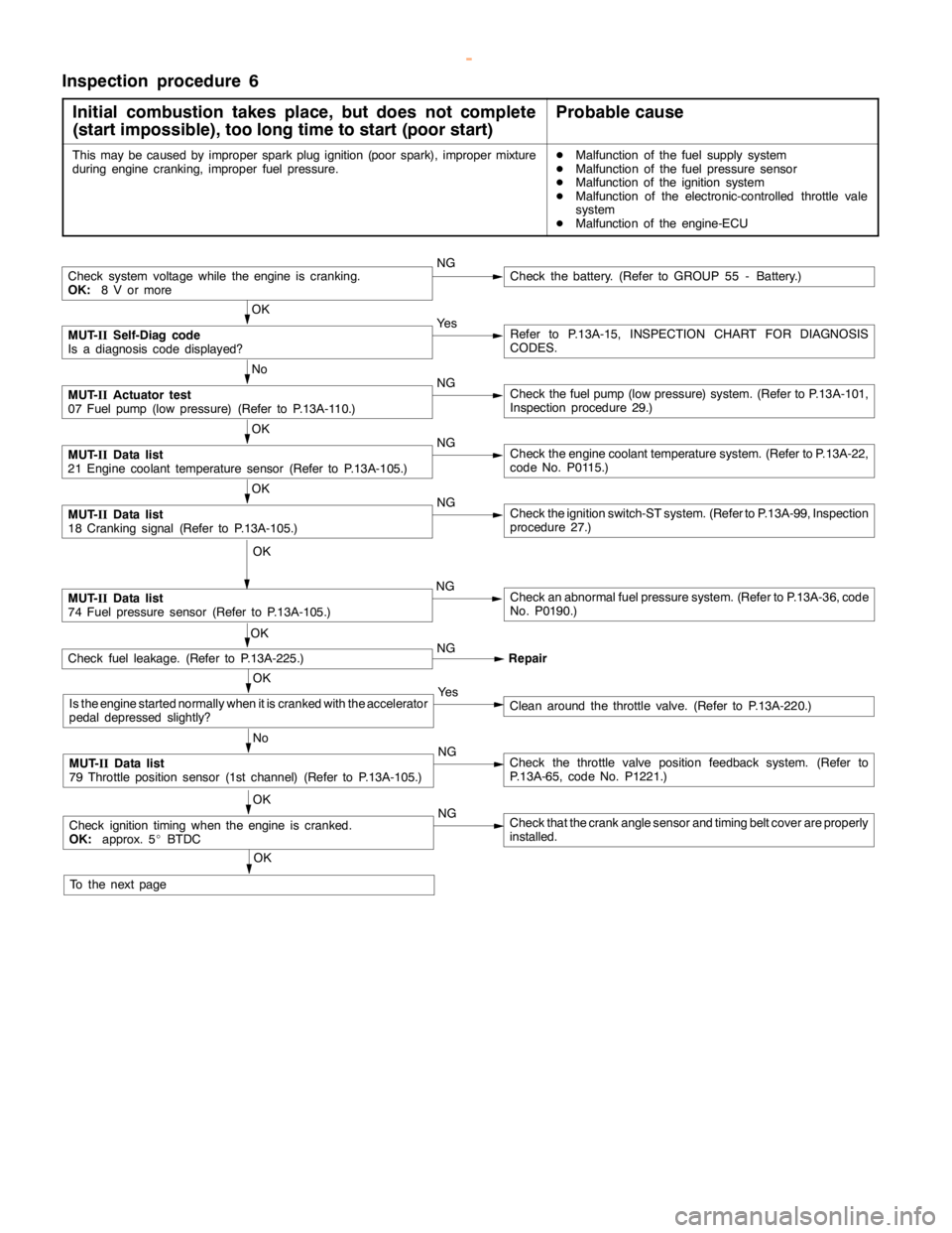
Inspection procedure 6
Initial combustion takes place, but does not complete
(start impossible), too long time to start (poor start)
Probable cause
This may be caused by improper sparkplug ignition (poorspark), improper mixture
during enginecranking, improper fuel pressure.DMalfunction of the fuel supply system
DMalfunction of the fuel pressure sensor
DMalfunction of the ignition system
DMalfunction of the electronic-controlled throttle vale
system
DMalfunction of the engine-ECU
Check system voltage while theengine iscranking.
OK:
8 V or moreNGCheck the battery. (Refer to GROUP 55 - Battery.)
OK
MUT-
IISelf-Diag code
Is a diagnosis code displayed?Ye sRefer to P.13A-15, INSPECTION CHART FOR DIAGNOSIS
CODES.
No
MUT-
IIActuator test
07 Fuel pump(low pressure) (Refer to P.13A-110.)NGCheck the fuelpump(low pressure) system. (Refer to P.13A-101,
Inspection procedure 29.)
OK
MUT-
IIData list
21 Engine coolant temperature sensor (Refer to P.13A-105.)NGCheck theengine coolant temperaturesystem. (Refer to P.13A-22,
code No. P0115.)
OK
MUT-
IIData list
18 Cranking signal (Refer to P.13A-105.)NGCheck the ignition switch-ST system. (Refer to P.13A-99, Inspection
procedure 27.)
OK
MUT-
IIData list
74 Fuel pressure sensor (Refer to P.13A-105.)NGCheck an abnormal fuel pressure system. (Refer to P.13A-36, code
No. P0190.)
Check fuel leakage. (Refer to P.13A-225.)NG
Repair
OK
Is the enginestarted normally when it is cranked with the accelerator
pedal depressed slightly?Ye sClean around the throttle valve. (Refer to P.13A-220.)
No
MUT-
IIData list
79 Throttle position sensor (1st channel) (Refer to P.13A-105.)NGCheck the throttle valve position feedback system. (Refer to
P.13A-65, code No. P1221.)
OK
Check ignitiontimingwhen theengine iscranked.
OK:
approx. 5_BTDCNGCheck that the crankanglesensor andtiming beltcover are properly
installed.
OK
To the nextpageOK
www.WorkshopManuals.co.uk
Purchased from www.WorkshopManuals.co.uk
Page 318 of 1839
GDI -Troubleshooting
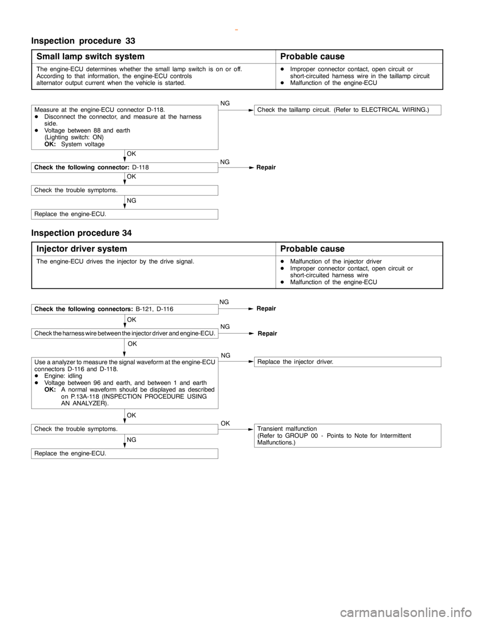
Inspection procedure 33
Small lamp switch system
Probable cause
The engine-ECU determines whether the small lampswitch is on or off.
According to that information, the engine-ECU controls
alternator output current when the vehicle is started.DImproper connector contact,opencircuit or
short-circuited harness wire in thetaillampcircuit
DMalfunction of the engine-ECU
NG
Replace the engine-ECU.
OK
Check the trouble symptoms.
OK
Check the following connector:
D-118NG
Repair
Measure at the engine-ECU connector D-118.
DDisconnect the connector, and measure at the harness
side.
DVoltage between 88 and earth
(Lighting switch: ON)
OK:
System voltageNGCheck thetaillampcircuit. (Refer to ELECTRICAL WIRING.)
Inspection procedure 34
Injector driver system
Probable cause
The engine-ECU drives the injector by the drive signal.DMalfunction of the injector driver
DImproper connector contact,opencircuit or
short-circuited harness wire
DMalfunction of the engine-ECU
OK
Check the harness wire between the injector driver and engine-ECU.
NG
Replace the engine-ECU.
OK
Check the trouble symptoms.Transient malfunction
(Refer to GROUP 00 - Points to Note for Intermittent
Malfunctions.) OK
Use a analyzer to measure the signal waveform at the engine-ECU
connectors D-116 and D-118.
DEngine: idling
DVoltage between 96 and earth, and between 1 and earth
OK:
A normal waveform should be displayed as described
on P.13A-118 (INSPECTION PROCEDURE USING
AN ANALYZER).NGReplace the injector driver.
NGCheck the following connectors:
B-121, D-116Repair
NG
Repair
OK
www.WorkshopManuals.co.uk
Purchased from www.WorkshopManuals.co.uk
Page 321 of 1839

GDI -Troubleshooting
Item
No.Reference
page Inspection
procedure
No. Normal condition Requirements Check items
25BarometricIgnition switch: ONAltitude: 0 m101 kPaCode No.13A-19
pressure sen-
sor
Altitude: 600 m95 kPa
P0105
Altitude: 1,200 m88 kPa
Altitude: 1,800 m81 kPa
26Accelerator
pedal positionIgnition switch: ON
(Depress and re-Release the accel-
erator pedal.ONProcedure
No.2813A-100
switchlease the accelera-
tor pedal several
times)
Depress the accel-
erator pedal slight-
ly.OFF
27Power steer-
ing fluid pres-Engine: IdlingSteering wheel sta-
tionaryOFFProcedure
No.3013A-102
sure switch
Steering wheel
turningON
28A/C switchEngine: Idling (The
A/C compressor isA/C switch: OFFOFFProcedure
No.3113A-100
A/C compressor is
running when the
A/C switch is on.)
A/C switch: ONON
No.31
31Small lamp
switchEngine: IdlingLighting switch:
OFFOFFProcedure
No.3313A-104
Lighting switch: ONON
34Air flow sensorEngine: After hav-Engine is idlingONCode No.13A-17
reset signaling warmed up
3,000 r/minOFF
P0100
37Volumetric effi-
ciencyDEngine coolant
temperature:Engine is idling20 - 40%--
80 - 95_C
DLamps, electric
cooling fan and2,500 r/min10 - 30%
cooling fan and
all accessories:
OFF
DTransmission:
Neutral
Engine is suddenly
racedVolumetric effi-
ciency increases in
response to racing
38Crank angle
sensorDEngine: Cranking [reading is possible
at 2,000 r/min or less]
DTachometer: ConnectedEngine speeds dis-
played on the
MUT-IIand
tachometer are
identical.--
www.WorkshopManuals.co.uk
Purchased from www.WorkshopManuals.co.uk
Page 322 of 1839

GDI -Troubleshooting
Item
No.Reference
page Inspection
procedure
No. Normal condition Requirements Check items
41Injector drive
time *2DEngine coolant
temperature:
80 - 95_CIdling0.3 - 0.8 ms*1--
80 - 95_C
DLamps, electric
cooling fan and
all accessories:
2,500 r/min0.4 - 1.0 ms
all accessories:
OFF
DTransmission:
Neutral
Sudden racingIncreases
44Ignition
advanceDEngine: After
warm-upIdling5-20_BTDC *1Code No.
P030013A-53
advancewarm-up
DSet a timing
light.
2,500 r/min15 - 35_BTDC
P0300
49A/C relayEngine: After
warm-up, idlingA/C switch: OFFOFF (compressor
clutch is not oper-
ating)Procedure
No.3113A-102
A/C switch: ONON (compressor
clutch is operating)
59Oxygen sen-
sor (rear)DTransmission:
2nd gear
DDrive with
throttle widely
open3,500 r/min600 - 1,000 mVCode No.
P013613A-31
67Stop lamp
switchIgnition switch: ONBrake pedal: De-
pressedOFFProcedure
No.3213A-103
Brake pedal: Re-
leasedON
68EGR valveDEngine coolant
temperature:
80 - 95_C
DLamps, electricIdling2 - 20 STEPCode No.
P040313A-60
cooling fan and
all accessories:
OFF
DTransmission:
Neutral
2,500 r/min0 - 10 STEP
74Fuel pressure
sensorDEngine coolant
temperature:
80 - 95_C
DLamps, electric
cooling fan and
all accessories:
OFF
DTransmission:
NeutralEngine: Idling4 - 6.9 MPaCode No.
P019013A-36
www.WorkshopManuals.co.uk
Purchased from www.WorkshopManuals.co.uk
Page 324 of 1839

GDI -Troubleshooting
ACTUATOR TEST REFERENCE TABLE
Item
No.Inspection
itemDrive contentsInspection contentsNormal conditionInspection
procedure
No.Reference
page
01InjectorsCut fuel to No. 1
injectorEngine:
After havingIdling condition
becomes differentCode No.
P020113A-38
02Cut fuel to No. 2
injector
warmed up/Engine
is idling
(Cut the fuel supply(becomes unsta-
ble).
Code No.
P020213A-40
03Cut fuel to No. 3
injectorto each injector in
turn and check
cylinders whichCode No.
P020313A-42
04Cut fuel to No. 4
injectordon’t affect idling.)Code No.
P020413A-44
05Cut fuel to No. 5
injectorCode No.
P020513A-46
06Cut fuel to No. 6
injectorCode No.
P020613A-48
07Fuel pump
(low pressure)Fuel pump
operates and
fuel is recirculated.Ignition switch: ONSound of opera-
tion is heard.Procedure
No. 2913A-101
08Purge
control
solenoid valveSolenoid valve
turns from OFF to
ON.Ignition switch: ONSound of opera-
tion can be heard
when solenoid
valve is
driven.Code No.
P044313A-62
17Basic ignition
timingSet the engine-
ECU to ignition
timing adjustment
modeIdling after engine
warm up5_BTDC--
21Condenser fanDrive the fan motorIgnition switch: ONThe fan motor
operatesProcedure
No.2113A-95
34Electronic-
controlled
throttle valve
systemStop the throttle
control servo.Ignition switch: ONThrottle valve is
opened slightly.Code No.
P122013A-64
www.WorkshopManuals.co.uk
Purchased from www.WorkshopManuals.co.uk