2000 MITSUBISHI MONTERO wiring
[x] Cancel search: wiringPage 11 of 1839

GENERAL -How to Use Troubleshooting/Inspection Service Points00-10
HOW TO USE THE INSPECTION PROCEDURES
The causes of a high frequency of problems occurring in electronic circuitry are generally the connectors,
components, the ECU and the harnesses between connectors, in that order. These inspection procedures
follow this order, and they first try to discover a problem with a connector or a defective component.
D
Indicator does not turn on or off even if control
mode switch is pressed.
D
Indicator switch should not be illuminated is
illuminated.Probable cause
OK
OK
OK
Measure at switch connector A-44
DDisconnect the connector, and measure at the harness
side.
DVoltage between terminal 6 - earth and terminal 8 -
earth
OK:Approx. 5V
OK
NG
Check the following connector.A-44
Repair
OK
Check trouble symptom.
Replace the ECS-ECU.
In the above cases, the ECS switch circuit is defective or the indicator
circuit is defective.
CHECKING PROCEDURE 4
2. Indicates inspection carried out using the
MUT-
II.
Indicates the operation and inspection proce-
dures.
Indicates the OK judgement conditions.
3. Detailed inspection procedures (methods)
such as component inspection andcircuit
inspection are listed on a separate page, and
are given here for reference.
5. Inspect the contact condition at each connectorterminal.
(Refer to Connector Inspection Service Points.)
The connector position can be located in the wiring diagram in the
electrical wiring manual bymeans ofthis symbol.
Caution
After carrying out connector inspection, always be sure to
reconnect the connector as it was before.
6. Confirm that there are trouble symptoms. If trouble symptomshave
disappeared, the connector may have been inserted incorrectly and the
trouble symptom mayhave disappeared during inspection.
If it seemsthat trouble symptoms still remain, proceed to the nextpage of
instructions.
7. If trouble symptoms still remain up to this stage, there is a possibility that there is an
open orshort circuit in the harness between the connectors, socheck the harness.
Alternatively, the cause may be a defectiveECU, so try replacing the ECU andcheck
if the trouble symptom disappears.
NGECU switch component inspection (Refer to P.33-44.)
NG
1. Comments on the diagnosis code ortrouble
symptom above.
MUT-II
Data list
17 Control mode selectionswitch
OK:Voltage changes between approx. 0V
®approx.
2.5V
®approx. 5V when the switch is operated.
4. Indicates voltage and resistance to be measured at a particular
connector.
(Refer to Connector Measurement Service Points.)
The connector position can be located in the wiring diagram in the
electrical wiring manual bymeans ofthis symbol.
Indicates operation and inspection procedures, inspection terminals
and inspection conditions.
Indicates the OK judgement conditions.
HARNESS INSPECTION
Check for an open or short circuit in the harness between the terminals which were defective according
to the connector measurements. Carry out this inspection while referring to the electrical wiring manual.
Here, “Check harness between power supply and terminal xx” also includes checking for blown fuses.
For inspection service points when there is a blown fuse, refer to “Inspection Service Points for a Blown
Fuse.”
MEASURES TO TAKE AFTER REPLACING THE ECU
If the trouble symptoms have not disappeared even after replacing the ECU, repeat the inspection procedure
from the beginning.
www.WorkshopManuals.co.uk
Purchased from www.WorkshopManuals.co.uk
Page 36 of 1839

GENERAL -Supplemental Restraint System (SRS)00-35
SRS-ECU
Terminal No.Destination of harnessCorrective action
1, 2, 3, 4Instrument panel wiring harness®Front wiring harness®Front
impact sensorRepair or replace each wiring
harness
7Instrument panel wiring harness®EarthRepair or replace Instrument
8Instrument panel wiring harness®Combination meter
(SRS warning lamp)
panel wiring harness
9, 10Instrument panel wiring harness®Front passenger’s air bag
module
11 , 1 2Instrument panel wiring harness®Clock spring®Driver’s air bag
module)Repair or replace the Instrument
panel wiring harness. Replace
clock spring.
13Instrument panel wiring harness®Junction block (fuse No.8)Repair or replace Instrument
16Instrument panel wiring harness®Junction block (fuse No.6)
panel wiring harness.
20Instrument panel wiring harness®Diagnosis connector
21, 22Side air bag wiring harness®Side air bag module (L.H.)Repair or replace side air bag
23, 24Side air bag wiring harness®Side air bag module (R.H.)
wiring harness.
34, 35, 36Side air bag wiring harness®Floor wiring harness®Side impact
sensor (L.H.)Repair or each wiring harness.
40, 41, 42Side air bag wiring harness®Floor wiring harness®Side impact
sensor (R.H.)
6. Inspection of the SRS-ECU harness connector should be carried out by the following procedure.
Insert the special tool (probe, MB991222, in the harness set) into the connector from harness side
(rear side), and connect the tester to this probe. If any tool than specified is used, damage to the
harness and other components will result. Furthermore, measurement should not be carried out by
touching the probe directly against the terminals from the front of the connector. The terminals are
plated to increase their conductivity, so that if they are touched directly by the probe, the plating
may break, which will cause drops in reliability.
www.WorkshopManuals.co.uk
Purchased from www.WorkshopManuals.co.uk
Page 309 of 1839

GDI -Troubleshooting
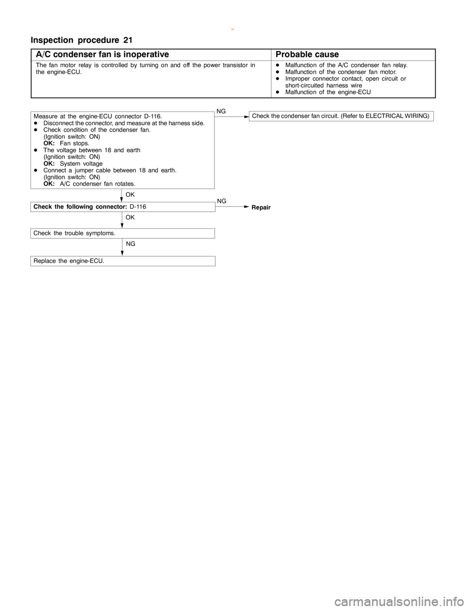
Inspection procedure 21
A/C condenser fan is inoperative
Probable cause
The fan motor relay is controlled by turning on and off the power transistor in
the engine-ECU.DMalfunction of the A/C condenser fan relay.
DMalfunction of the condenser fan motor.
DImproper connector contact,opencircuit or
short-circuited harness wire
DMalfunction of the engine-ECU
OK
Replace the engine-ECU.NG
Repair
OK
Check the trouble symptoms.
Check the following connector:
D-116
Measure at the engine-ECU connector D-116.
DDisconnect the connector, and measure at the harness side.
DCheck condition of the condenser fan.
(Ignition switch: ON)
OK:
Fan stops.
DThe voltage between 18 and earth
(Ignition switch: ON)
OK:
System voltage
DConnect a jumper cable between 18 and earth.
(Ignition switch: ON)
OK:
A/C condenser fan rotates.NGCheck the condenser fan circuit. (Refer to ELECTRICAL WIRING)
NG
www.WorkshopManuals.co.uk
Purchased from www.WorkshopManuals.co.uk
Page 318 of 1839

GDI -Troubleshooting
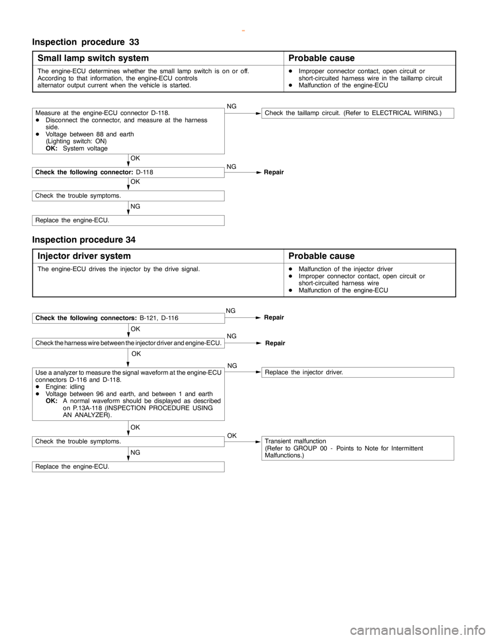
Inspection procedure 33
Small lamp switch system
Probable cause
The engine-ECU determines whether the small lampswitch is on or off.
According to that information, the engine-ECU controls
alternator output current when the vehicle is started.DImproper connector contact,opencircuit or
short-circuited harness wire in thetaillampcircuit
DMalfunction of the engine-ECU
NG
Replace the engine-ECU.
OK
Check the trouble symptoms.
OK
Check the following connector:
D-118NG
Repair
Measure at the engine-ECU connector D-118.
DDisconnect the connector, and measure at the harness
side.
DVoltage between 88 and earth
(Lighting switch: ON)
OK:
System voltageNGCheck thetaillampcircuit. (Refer to ELECTRICAL WIRING.)
Inspection procedure 34
Injector driver system
Probable cause
The engine-ECU drives the injector by the drive signal.DMalfunction of the injector driver
DImproper connector contact,opencircuit or
short-circuited harness wire
DMalfunction of the engine-ECU
OK
Check the harness wire between the injector driver and engine-ECU.
NG
Replace the engine-ECU.
OK
Check the trouble symptoms.Transient malfunction
(Refer to GROUP 00 - Points to Note for Intermittent
Malfunctions.) OK
Use a analyzer to measure the signal waveform at the engine-ECU
connectors D-116 and D-118.
DEngine: idling
DVoltage between 96 and earth, and between 1 and earth
OK:
A normal waveform should be displayed as described
on P.13A-118 (INSPECTION PROCEDURE USING
AN ANALYZER).NGReplace the injector driver.
NGCheck the following connectors:
B-121, D-116Repair
NG
Repair
OK
www.WorkshopManuals.co.uk
Purchased from www.WorkshopManuals.co.uk
Page 329 of 1839

GDI -Troubleshooting
Terminal
No.Normal condition Check requirements (engine condition) Check item
94Accelerator pedal position
sensor (1st channel)Ignition switch:
ONRelease the acceler-
ator pedal.0.3 - 1.0 V*1
Depress the
accelerator pedal
fully.4.2 - 5.5 V*2
96Injector open circuit check
signalEngine: Increase engine speed from
idle speed to 4,000 r/min.Decreases slightly (approx.
0.7V) from 4.5 V - 5.0 V.
99Ignition switch - IGIgnition switch: ONSystem voltage
NOTE
Check if the difference in output between *1 and *2 is 4 V or more.
CHECK CHART FOR RESISTANCE AND CONTINUITY
BETWEEN TERMINALS
1. Turn the ignition switch to OFF.
2. Disconnect the engine-ECU connector.
3. Measure the resistance and check for continuity between
the terminals of the engine-ECU harness-side connector
while referring to the check chart.
NOTE
(1) When measuring resistance and checking continuity,
a harness for checking contact pin pressure should
be used instead of inserting a test probe.
(2) Checking need not be carried out in the order given
in the chart.
Caution
If the terminals that should be checked are mistaken,
or if connector terminals are not correctly shorted
to earth, damage may be caused to the vehicle wiring,
sensors, engine-ECU and/or ohmmeter.
Be careful to prevent this!
4. If the ohmmeter shows any deviation from the standard
value, check the corresponding sensor, actuator and
related electrical wiring, and then repair or replace.
5. After repair or replacement, recheck with the ohmmeter
to confirm that the repair or replacement has corrected
the problem.
www.WorkshopManuals.co.uk
Purchased from www.WorkshopManuals.co.uk
Page 401 of 1839

Page 409 of 1839

Page 422 of 1839
