2000 MITSUBISHI MONTERO brake light
[x] Cancel search: brake lightPage 322 of 1839

GDI -Troubleshooting
Item
No.Reference
page Inspection
procedure
No. Normal condition Requirements Check items
41Injector drive
time *2DEngine coolant
temperature:
80 - 95_CIdling0.3 - 0.8 ms*1--
80 - 95_C
DLamps, electric
cooling fan and
all accessories:
2,500 r/min0.4 - 1.0 ms
all accessories:
OFF
DTransmission:
Neutral
Sudden racingIncreases
44Ignition
advanceDEngine: After
warm-upIdling5-20_BTDC *1Code No.
P030013A-53
advancewarm-up
DSet a timing
light.
2,500 r/min15 - 35_BTDC
P0300
49A/C relayEngine: After
warm-up, idlingA/C switch: OFFOFF (compressor
clutch is not oper-
ating)Procedure
No.3113A-102
A/C switch: ONON (compressor
clutch is operating)
59Oxygen sen-
sor (rear)DTransmission:
2nd gear
DDrive with
throttle widely
open3,500 r/min600 - 1,000 mVCode No.
P013613A-31
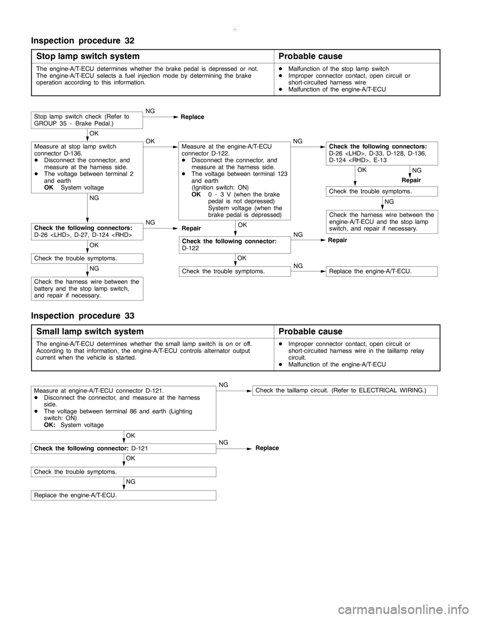
67Stop lamp
switchIgnition switch: ONBrake pedal: De-
pressedOFFProcedure
No.3213A-103
Brake pedal: Re-
leasedON
68EGR valveDEngine coolant
temperature:
80 - 95_C
DLamps, electricIdling2 - 20 STEPCode No.
P040313A-60
cooling fan and
all accessories:
OFF
DTransmission:
Neutral
2,500 r/min0 - 10 STEP
74Fuel pressure
sensorDEngine coolant
temperature:
80 - 95_C
DLamps, electric
cooling fan and
all accessories:
OFF
DTransmission:
NeutralEngine: Idling4 - 6.9 MPaCode No.
P019013A-36
www.WorkshopManuals.co.uk
Purchased from www.WorkshopManuals.co.uk
Page 328 of 1839

GDI -Troubleshooting
Terminal
No.Normal condition Check requirements (engine condition) Check item
63Stop lamp switchDepress the brake pedal.System voltage
Release the brake pedal.0-3V
65A/C switch (2nd channel)Refer to GROUP 55 - Troubleshooting “Check at the A/C-ECU
terminal, engine-ECU output terminals.”
66Clutch switchDepress the clutch pedal.0-3V
Release the clutch pedal.System voltage
68Ignition switch-STEngine: Cranking8V or more
71Oxygen sensor (front)Engine: Warm up, and then hold the
engine speed at 2,500r/min (Use a
digital voltmeter).0«0.8 V alternates.
76Air flow sensor reset signalEngine: Idling0-1V
Engine: 3,000 r/min6-9V
78Throttle position sensor
(2nd channel)Ignition switch:
ONRelease the
accelerator pedal.4.5 - 5.5 V
Depress the
accelerator pedal
fully.0.4 - 0.6 V
79Accelerator pedal position
switchIgnition switch:
ONRelease the
accelerator pedal.0-1V
Depress the
accelerator pedal
fully.4V or more
80Vehicle speed sensorDIgnition switch: ON
DMove the vehicle forward.0«system voltage
alternates.
83A/C switch (1st channel)Engine: IdlingA/C switch: OFF0-3V
A/C switch: ON
(Compressor is
operating)System voltage
88Small lamp switchLighting switch: OFF0-3V
Lighting switch: ON (Taillamp: ON)System voltage
89Oxygen sensor heaterEngine: Idling0-3V
(front)
Engine: 3,500 r/minSystem voltage
90Oxygen sensor heaterEngine: Idling0-3V
(rear)
Engine: 3,500 r/minSystem voltage
92Fuel pressure sensorEngine: Idling0.3 - 4.7 V
www.WorkshopManuals.co.uk
Purchased from www.WorkshopManuals.co.uk
Page 409 of 1839

Page 421 of 1839

Page 1573 of 1839

54A-3
ON-VEHICLE SERVICE 46......................
Room Lamp Delay-off Time Adjustment
Procedure 46...............................
REAR COMBINATION LAMP 47...........
SPECIAL TOOLS 47...........................
TROUBLESHOOTING 47.......................
REAR COMBINATION LAMP 47................
HIGH-MOUNTED STOP LAMP 48.........
COLUMN SWITCH 48....................
SPECIAL TOOLS 48...........................
COLUMN SWITCH 48..........................
HAZARD WARNING LAMP SWITCH 50....
SPECIAL TOOLS 50...........................
HAZARD WARNING LAMP SWITCH 50.........
HORN 51................................
CIGARETTE LIGHTER 51.................
ACCESSORY SOCKET 51................
RHEOSTAT 52...........................
CLOCK OR CENTER DISPLAY 53........
TROUBLESHOOTING 53.......................
CLOCK OR CENTER DISPLAY 67..............
RADIO/TAPE PLAYER 68.................
TROUBLESHOOTING 68.......................
RADIO AND CD AUTO CHANGER 81..........
FRONT SPEAKERS 82...................
REAR SPEAKERS 82.....................
ANTENNA83 ............................DEFOGGER 86...........................
TROUBLESHOOTING
ON-VEHICLE SERVICE 86.....................
Printed Heater Check 86.....................
Defogger Relay Continuity Check 86...........
DEFOGGER SWITCH 87.......................
SMART WIRING SYSTEM (SWS)
Refer to GROUP 54B ....................
RADIATOR (RADIATOR FAN MOTOR)
Refer to GROUP 14 ......................
AUTOMATIC TRANSMISSION
Refer to GROUP 23 ......................
ANTI-LOCK BRAKE SYSTEM (ABS)
Refer to GROUP 35B ....................
DOOR HANDLE LATCH (DOOR LOCK)
Refer to GROUP 42 ......................
DOOR GLASS-REGULATOR (POWER
WINDOWS)
Refer to GROUP 42 ......................
KEYLESS ENTRY SYSTEM
Refer to GROUP 42 ......................
WINDSHIELD WIPER/WASHER
Refer to GROUP 51 ......................
REAR WIPER/WASHER
Refer to GROUP 51 ......................
SRS AIRBAG Refer to GROUP 52B......
HEATER Refer to GROUP 55.............
AIR CONDITIONER Refer to GROUP 55...
www.WorkshopManuals.co.uk
Purchased from www.WorkshopManuals.co.uk