2000 MITSUBISHI MONTERO battery
[x] Cancel search: batteryPage 46 of 1839

3 MSB-00E00-505
3. Details:
Contents of Attachment are to be added to GROUP 00 (GENERAL).
PRECAUTIONS BEFORE SERVICE
LEARNING FUNCTION OF GDI ENGINE
1. Purpose
On the GDI engine equipped cars, when replacement of the ECU (for engine control) or resetting
of the battery* has been performed, an idle learning function of the ECU (for engine control) will
be required.
The idle learning function will be completed by running the engine at idle by the following procedure.
NOTE:
*: Disconnection of ECU (for engine control) battery backup power supply (disconnection of battery
terminals or ECU connectors)
2. Idle Learning Procedure
(1) Start the engine, and warm up the engine until its coolant temperature reaches 85°C or higher.
When the engine coolant temperature is 85°C or higher, you have only to turn the ignition
switch to the ON position.
(2) Turn the ignition switch to the LOCK (OFF) position, and stop the engine.
(3) After lapse of ten or more seconds, restart the engine.
(4) Run the engine at idle for ten minutes under the following conditions.
DTransmission: Neutral (P range for automatic transmission)
DAir conditioner and heater: Not operational
DEngine coolant temperature: 83°C or higher
(5) Stop the engine.
(6) Restart the engine, and run it at idle for ten minutes under the following condition.
DTransmission: Neutral (P range for automatic transmission)
DAir conditioner: Operational (Temperature set at “maximum cool”, fan at high speed, and
windows fully opened)
DEngine coolant temperature: 83°C or higher
(7) Repeat steps (5) and (6).
NOTE:
1) When the atmospheric temperature is 20°C or more and the air conditioner has continuously
been operated, step (7) may be omitted.
2) During idling operation of the engine in steps (4) and (6), when engine operation switches
from lean operation to stoichiometric operation, engine stall can occur. In this case, clean the
throttle body (throttle valve) thoroughly, and then repeat step (1) and the subsequent steps.
www.WorkshopManuals.co.uk
Purchased from www.WorkshopManuals.co.uk
Page 53 of 1839

GENERAL -Precautions Before Service00-5
PRECAUTIONS BEFORE SERVICE
SUPPLEMENTAL RESTRAINT SYSTEM (SRS), SEAT BELT WITH PRE-TENSIONER
1. Items to follow when servicing SRS
(1) Be sure to read GROUP 52B - Supplemental Restraint System (SRS).
For safe operations, please follow the directions and heed all warnings.
(2) Wait at least 60 seconds after disconnecting the battery cable before doing any further work.
The SRS system is designed to retain enough voltage to deploy the air bag even after the battery
has been disconnected. Serious injury may result from unintended air bag deployment if work
is done on the SRS system immediately after the battery cable is disconnected.
(3) Warning labels must be heeded when servicing or handling SRS components and seat belt with
pre-tensioner. Warning labels are located in the following locations.
DHood
DSun visor
DGlove box
DSRS-ECU
DSteering wheel
DSteering gearbox
DAir bag module (driver’s side and front passenger’s side)
DFront impact sensor
DClock spring
DSeat belt with pre-tensioner
DSide air bag module
DSide impact sensor
(4) Always use the designated special tools and test equipment.
(5) Store components removed from the SRS and seat belt with pre-tensioner in a clean and dry
place.
The air bag module and seat belt with pre-tensioner should be stored on a flat surface and
placed so that the pad surface is facing upward.
Do not place anything on top of it.
(6) Never attempt to disassemble or repair the SRS components (SRS-ECU, air bag module, clock
spring and side impact sensor) and seat belt with pre-tensioner.
(7) Whenever you finish servicing the SRS and seat belt with pre-tensioner, check the SRS warning
lamp operation to make sure that the system functions properly.
(8) Be sure to deploy the air bag and seat belt with pre-tensioner before disposing of the air bag
module and seat belt with pre-tensioner or disposing of a vehicle equipped with an air bag and
seat belt with pre-tensioner. (Refer to GROUP 52B - Air Bag Module and Seat Belt with Pre-tensioner
Disposal Procedures.)
2. Observe the following when carrying out operations on places where SRS components and seat
belt with pre-tensioner are installed, including operations not directly related to the SRS air bag and
seat belt with pre-tensioner.
(1) When removing or installing parts do not allow any impact or shock to the SRS components
and seat belt with pre-tensioner.
(2) SRS components and seat belt with pre-tensioner should not be subjected to heat, so remove
the SRS components and seat belt with pre-tensioner before drying or baking the vehicle after
painting.
DSRS-ECU, air bag module, clock spring, front and side impact sensors: 93_C or more
DSeat belt with pre-tensioner: 90_C or more
After re-installing them, check the SRS warning lamp operation to make sure that the system
functions properly.
www.WorkshopManuals.co.uk
Purchased from www.WorkshopManuals.co.uk
Page 226 of 1839

GDI -Troubleshooting
FREEZE FRAME DATA
When the engine-ECU detects a malfunction and stores a
diagnosis code, it also stores a current status of the engine.
This function is called “Freeze frame data.” By analyzing
this “freeze frame” data with the MUT-II, an effective
troubleshooting can be performed.
Data itemUnit
Engine coolant temperature sensor_C
Engine speedr/min
Vehicle speedkm/h
Long-term fuel compensation (long-term
fuel trim)%
Short-term fuel compensation (short-term
fuel trim)%
Fuel control condi-Open loopOL
tion
Closed loopCL
Open loop owing to
drive conditionOL-DRV.
Open loop owing to
system malfunctionOL-SYS.
Closed loop based
on one oxygen sen-
sorCL-H02S
Calculation load value%
Diagnosis code during data recording-
NOTE
If malfunctions have been detected in multiple systems, store
one malfunction only, which has been detected first.
READINESS TEST STATUS
The engine-ECU monitors the following main diagnosis items,
judges if these items are in good condition or not, and the
stores its history. This history can be read out by using MUT-II.
(If the ECU has judged a item before, the MUT-II displays
“Complete.”)
In addition, if diagnosis codes are erased or the battery
cable is disconnected, this history will also be erased (the
memory will be reset).
DCatalyst: P0420
DOxygen sensor: P0130
DOxygen sensor heater: P0135, P0141
www.WorkshopManuals.co.uk
Purchased from www.WorkshopManuals.co.uk
Page 233 of 1839
GDI -Troubleshooting
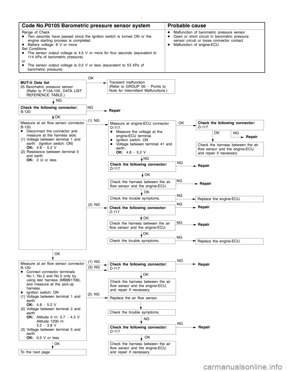
Code No.P0105 Barometric pressure sensor systemProbable cause
Range of Check
DTwo seconds have passed since the ignition switch is turned ON or the
engine startingprocess is completed.
DBattery voltage: 8 V or more
Set Conditions
DThe sensor output voltage is 4.5 V or more for four seconds (equivalent to
114 kPa of barometric pressure)
or
DThe sensor output voltage is 0.2 V or less (equivalent to 53 kPa of
barometric pressure)DMalfunction of barometric pressure sensor
DOpen or short circuit in barometric pressure
sensor circuit or loose connector contact
DMalfunction of engine-ECU
(2) NGCheck the following connector:
D-117NG
Repair
OK
Check the harness between the air
flow sensor and the engine-ECU,
and repair if necessary.
MUT-
IIData list
25 Barometric pressure sensor
(Refer to P.13A-105, DATA LIST
REFERENCE TABLE.)OKTransient malfunction
(Refer to GROUP 00 - Points to
Note for Intermittent Malfunctions.)
NG
NG
Repair
OK
Measure at air flow sensor connector
B-120.
DDisconnect the connector and
measure at the harness side.
(1) Voltage between terminal 1 and
earth (Ignition switch: ON)
OK:
4.8 - 5.2 V
(2) Resistance between terminal 5
and earth
OK:
2Wor less(1) NGMeasure at engine-ECU connector
D-117.
DMeasure the voltage at the
engine-ECU terminal.
DIgnition switch: ON
DVoltage between terminal 41 and
earth
OK:
4.8 - 5.2 VOKCheck the following connector:
D-117
NG
Repair
NG
Check the following connector:
D-117NG
Repair
OK
Check the harness between the air
flow sensor and the engine-ECU.NG
Repair
OK
Check the trouble symptoms.NGReplace the engine-ECU.
OK
Measure at air flow sensor connector
B-120.
DConnect connector terminals
No.1, No.2 and No.5 only by
using test harness (MB991709),
and measure at the pick-up
harness.
DIgnition switch: ON
(1) Voltage between terminal 1 and
earth
OK:
4.8 - 5.2 V
(2) Voltage between terminal 2 and
earth
OK:
Altitude 0 m: 3.7 - 4.3 V
Altitude 1200 m:
3.2 - 3.8 V
(3) Voltage between terminal 5 and
earth
OK:
0.5 V or less(1) NGCheck the following connector:
D-117NG
Repair
OK
Check the harness between the air
flow sensor and the engine-ECU,
and repair if necessary.
OK
To the nextpage(3) NG
(2) NG
Replace the air flow sensor.
NG
Check the following connector:
D-117NG
Repair
OK
Check the harness between the air
flow sensor and the engine-ECU,
and repair if necessary.
OK
Check the harness between the air
flow sensor and the engine-ECU.NG
Repair
OK
Check the trouble symptoms.NGReplace the engine-ECU.
Check the following connector:
B-120
Check the trouble symptoms.
www.WorkshopManuals.co.uk
Purchased from www.WorkshopManuals.co.uk
Page 244 of 1839
GDI -Troubleshooting
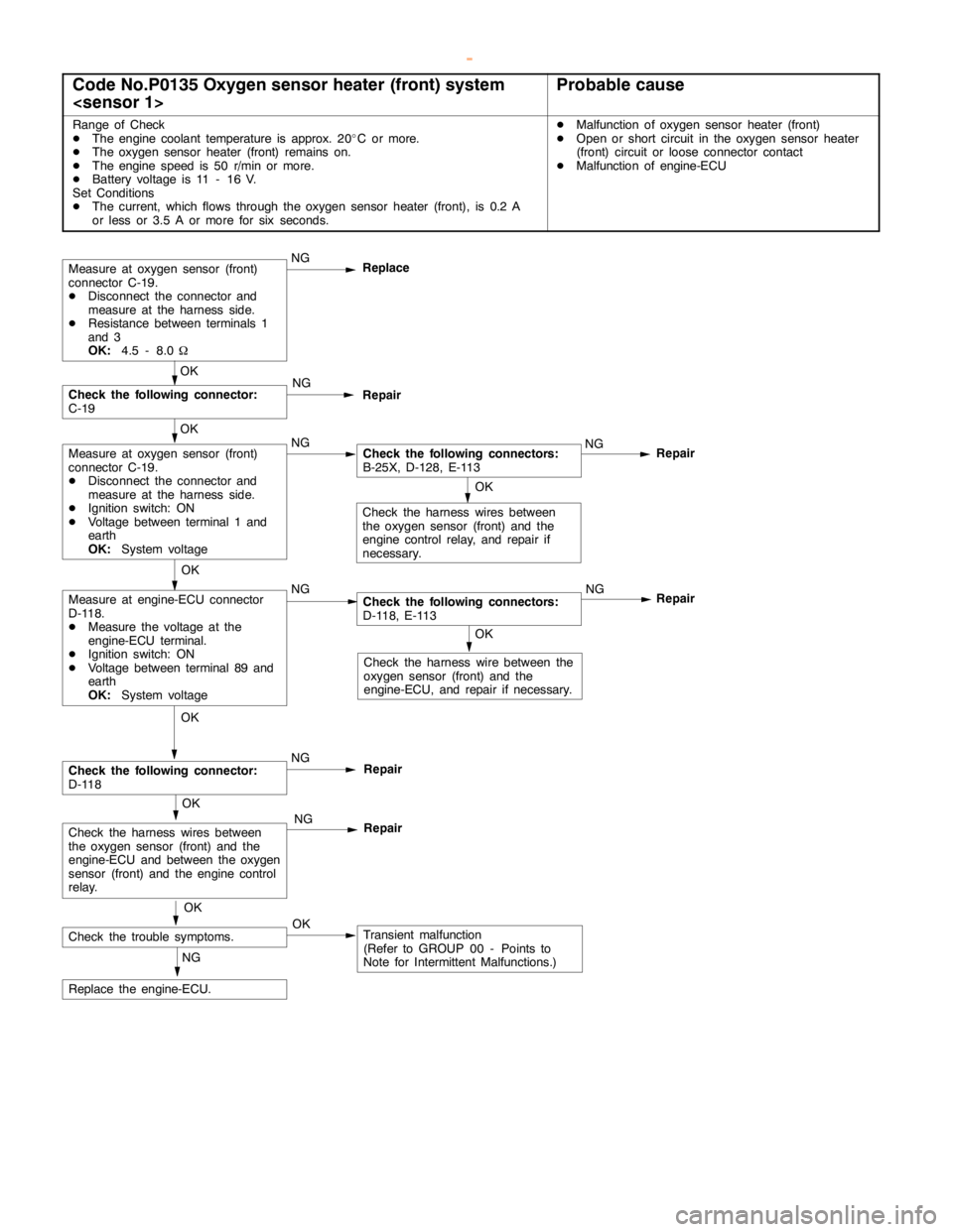
Code No.P0135 Oxygen sensor heater (front) system
Range of Check
DThe engine coolant temperature is approx. 20_C or more.
DThe oxygen sensor heater (front) remains on.
DThe enginespeed is 50 r/min or more.
DBattery voltage is 11 - 16 V.
Set Conditions
DThe current, which flows through the oxygen sensor heater (front), is 0.2 A
or less or 3.5 A or more for six seconds.DMalfunction of oxygen sensor heater (front)
DOpen or short circuit in the oxygen sensor heater
(front) circuit or loose connector contact
DMalfunction of engine-ECU
OK
Check the harness wire between the
oxygen sensor (front) and the
engine-ECU, and repair if necessary.
Repair
OK
Measure at engine-ECU connector
D-118.
DMeasure the voltage at the
engine-ECU terminal.
DIgnition switch: ON
DVoltage between terminal 89 and
earth
OK:
System voltageNGCheck the following connectors:
D-118, E-113NG
OK
Check the harness wires between
the oxygen sensor (front) and the
engine controlrelay, and repair if
necessary.
Measure at oxygen sensor (front)
connector C-19.
DDisconnect the connector and
measure at the harness side.
DResistance between terminals 1
and 3
OK:
4.5 - 8.0WNG
Replace
Repair
OK
Measure at oxygen sensor (front)
connector C-19.
DDisconnect the connector and
measure at the harness side.
DIgnition switch: ON
DVoltage between terminal 1 and
earth
OK:
System voltageNGCheck the following connectors:
B-25X, D-128, E-113NG
OK
Check the following connector:
C-19NG
Repair
OK
Check the trouble symptoms.OKTransient malfunction
(Refer to GROUP 00 - Points to
Note for Intermittent Malfunctions.) NG
Replace the engine-ECU.
OK
Check the following connector:
D-118NG
Repair
OK
Check the harness wires between
the oxygen sensor (front) and the
engine-ECU and between the oxygen
sensor (front) and theengine control
relay.NG
Repair
www.WorkshopManuals.co.uk
Purchased from www.WorkshopManuals.co.uk
Page 247 of 1839
GDI -Troubleshooting
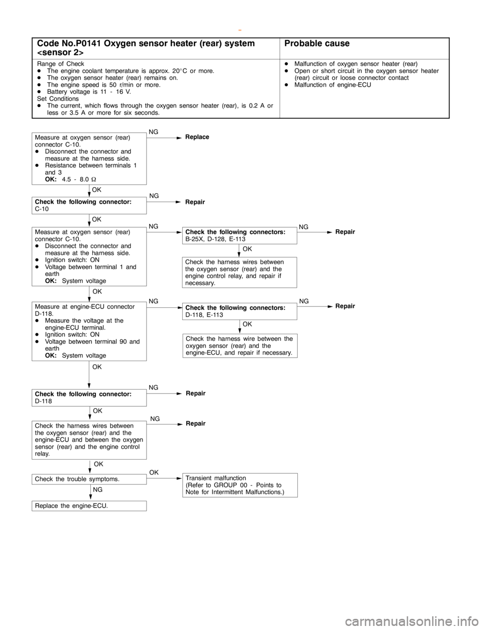
Code No.P0141 Oxygen sensor heater (rear) system
Range of Check
DThe engine coolant temperature is approx. 20_C or more.
DThe oxygen sensor heater (rear) remains on.
DThe enginespeed is 50 r/min or more.
DBattery voltage is 11 - 16 V.
Set Conditions
DThe current, which flows through the oxygen sensor heater (rear), is 0.2 A or
less or 3.5 A or more for six seconds.DMalfunction of oxygen sensor heater (rear)
DOpen or short circuit in the oxygen sensor heater
(rear) circuit or loose connector contact
DMalfunction of engine-ECU
OK
Check the harness wire between the
oxygen sensor (rear) and the
engine-ECU, and repair if necessary.
Repair
OK
Measure at engine-ECU connector
D-118.
DMeasure the voltage at the
engine-ECU terminal.
DIgnition switch: ON
DVoltage between terminal 90 and
earth
OK:
System voltageNGCheck the following connectors:
D-118, E-113NG
OK
Check the harness wires between
the oxygen sensor (rear) and the
engine controlrelay, and repair if
necessary.
Measure at oxygen sensor (rear)
connector C-10.
DDisconnect the connector and
measure at the harness side.
DResistance between terminals 1
and 3
OK:
4.5 - 8.0WNG
Replace
Repair
OK
Measure at oxygen sensor (rear)
connector C-10.
DDisconnect the connector and
measure at the harness side.
DIgnition switch: ON
DVoltage between terminal 1 and
earth
OK:
System voltageNGCheck the following connectors:
B-25X, D-128, E-113NG
OK
Check the following connector:
C-10NG
Repair
OK
Check the trouble symptoms.OKTransient malfunction
(Refer to GROUP 00 - Points to
Note for Intermittent Malfunctions.) NG
Replace the engine-ECU.
OK
Check the following connector:
D-118NG
Repair
OK
Check the harness wires between
the oxygen sensor (rear) and the
engine-ECU and between the oxygen
sensor (rear) and theengine control
relay.NG
Repair
www.WorkshopManuals.co.uk
Purchased from www.WorkshopManuals.co.uk
Page 252 of 1839
GDI -Troubleshooting
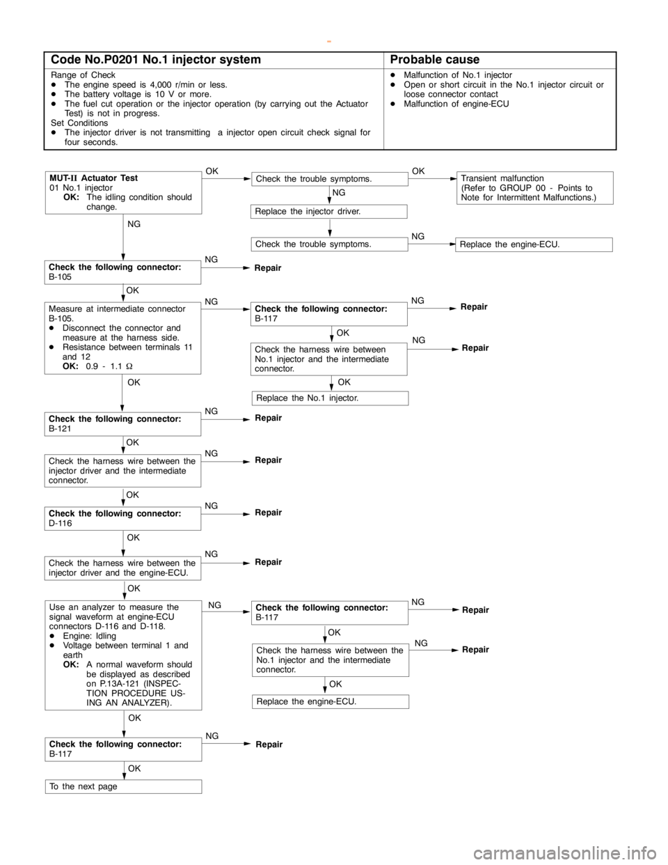
Code No.P0201 No.1 injector systemProbable cause
Range of Check
DThe enginespeed is 4,000 r/min or less.
DThe battery voltage is 10 V or more.
DThe fuel cut operation or the injector operation (by carrying out the Actuator
Test) is not in progress.
Set Conditions
DThe injector driver is not transmitting a injectoropencircuit check signal for
four seconds.DMalfunction of No.1 injector
DOpen or short circuit in the No.1 injector circuit or
loose connector contact
DMalfunction of engine-ECU
NG
Check the following connector:
B-105NG
Repair
OK
NG
Repair
MUT-
IIActuator Test
01 No.1 injector
OK:
The idling condition should
change.OKCheck the trouble symptoms.OKTransient malfunction
(Refer to GROUP 00 - Points to
Note for Intermittent Malfunctions.)
NG
Replace the injector driver.
Check the trouble symptoms.NGReplace the engine-ECU.
OK
Measure at intermediate connector
B-105.
DDisconnect the connector and
measure at the harness side.
DResistance between terminals 11
and 12
OK:
0.9 - 1.1WNGCheck the following connector:
B-117NG
Repair
OK
Replace the No.1 injector.
OK
Check the following connector:
B-121NG
Repair
OK
Check the harness wire between the
injector driver and the intermediate
connector.NG
Repair
OK
Check the following connector:
D-116NG
Repair
OK
Check the harness wire between the
injector driver and the engine-ECU.NG
Repair
OK
Use an analyzer to measure the
signal waveform at engine-ECU
connectors D-116 and D-118.
DEngine: Idling
DVoltage between terminal 1 and
earth
OK:
A normal waveform should
be displayed as described
on P.13A-121 (INSPEC-
TION PROCEDURE US-
ING AN ANALYZER).NGCheck the following connector:
B-117
OK
Check the following connector:
B-117NG
Repair
OK
To the nextpageNG
OK
OK
Check the harness wire between the
No.1 injector and the intermediate
connector.NG
Replace the engine-ECU.
Repair
Repair
Check the harness wire between
No.1 injector and the intermediate
connector.
www.WorkshopManuals.co.uk
Purchased from www.WorkshopManuals.co.uk
Page 254 of 1839
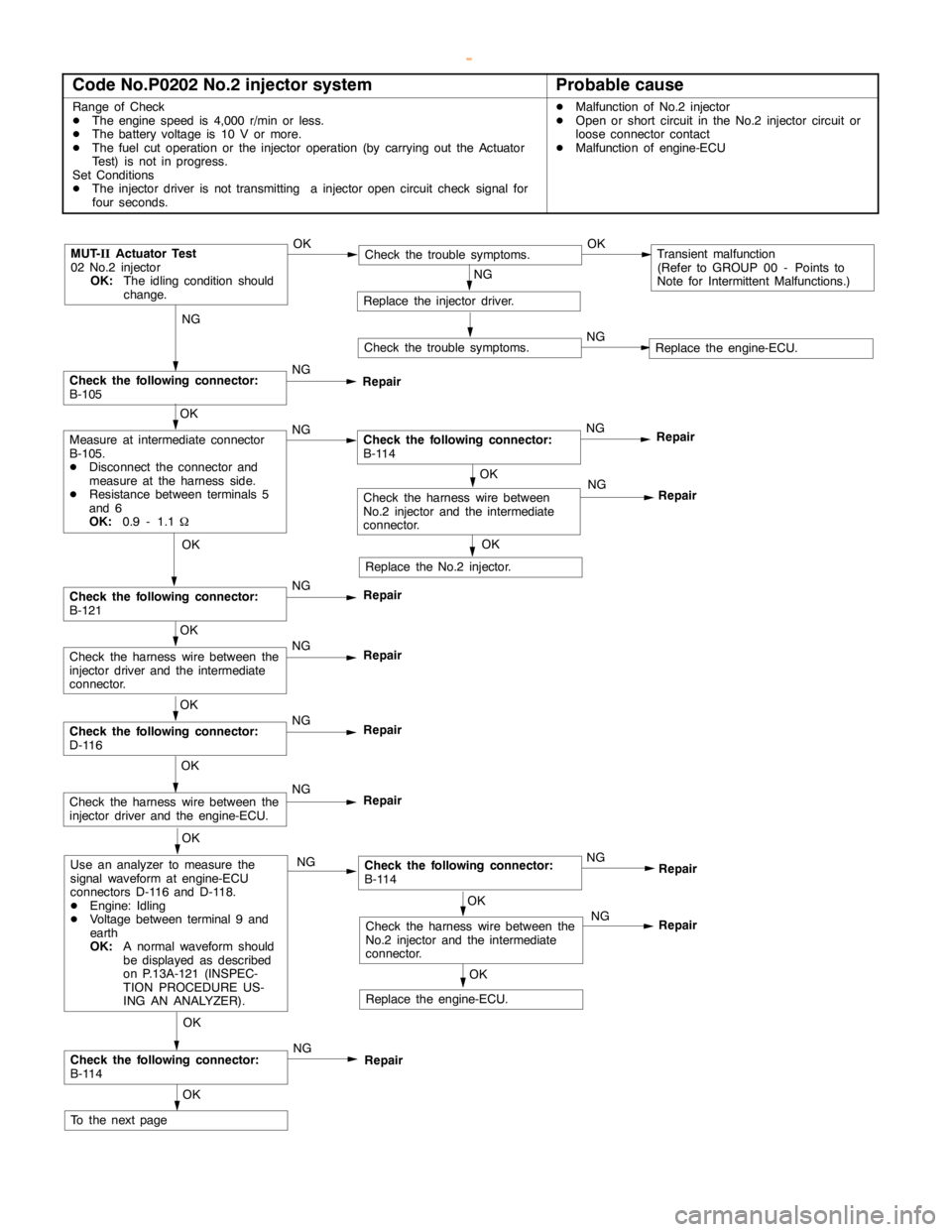
GDI -Troubleshooting
Code No.P0202 No.2 injector systemProbable cause
Range of Check
DThe enginespeed is 4,000 r/min or less.
DThe battery voltage is 10 V or more.
DThe fuel cut operation or the injector operation (by carrying out the Actuator
Test) is not in progress.
Set Conditions
DThe injector driver is not transmitting a injectoropencircuit check signal for
four seconds.DMalfunction of No.2 injector
DOpen or short circuit in the No.2 injector circuit or
loose connector contact
DMalfunction of engine-ECU
NG
Check the following connector:
B-105NG
Repair
OK
NG
Repair
MUT-
IIActuator Test
02 No.2 injector
OK:
The idling condition should
change.OKCheck the trouble symptoms.OKTransient malfunction
(Refer to GROUP 00 - Points to
Note for Intermittent Malfunctions.)
NG
Replace the injector driver.
Check the trouble symptoms.NGReplace the engine-ECU.
OK
Measure at intermediate connector
B-105.
DDisconnect the connector and
measure at the harness side.
DResistance between terminals 5
and 6
OK:
0.9 - 1.1WNGCheck the following connector:
B-114NG
Repair
OK
Replace the No.2 injector.
OK
Check the following connector:
B-121NG
Repair
OK
Check the harness wire between the
injector driver and the intermediate
connector.NG
Repair
OK
Check the following connector:
D-116NG
Repair
OK
Check the harness wire between the
injector driver and the engine-ECU.NG
Repair
OK
Use an analyzer to measure the
signal waveform at engine-ECU
connectors D-116 and D-118.
DEngine: Idling
DVoltage between terminal 9 and
earth
OK:
A normal waveform should
be displayed as described
on P.13A-121 (INSPEC-
TION PROCEDURE US-
ING AN ANALYZER).NGCheck the following connector:
B-114
OK
Check the following connector:
B-114NG
Repair
OK
To the nextpageNG
OK
OK
Check the harness wire between the
No.2 injector and the intermediate
connector.NG
Replace the engine-ECU.
Repair
Repair
Check the harness wire between
No.2 injector and the intermediate
connector.
www.WorkshopManuals.co.uk
Purchased from www.WorkshopManuals.co.uk