2000 MITSUBISHI MONTERO turn signal bulb
[x] Cancel search: turn signal bulbPage 310 of 1839
GDI -Troubleshooting
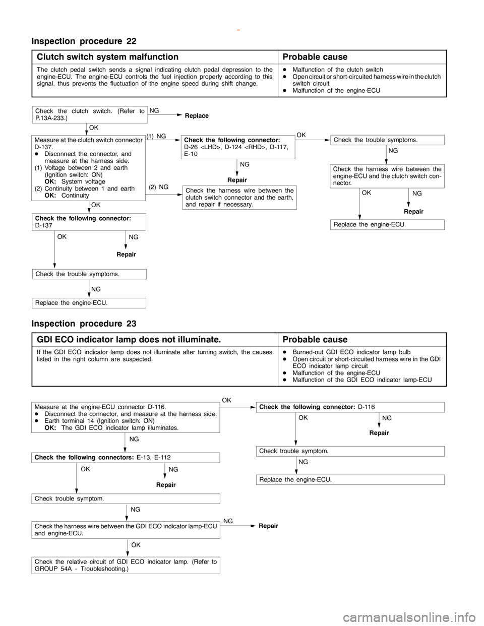
Inspection procedure 22
Clutch switch system malfunction
Probable cause
The clutchpedalswitch sends a signal indicating clutchpedal depression to the
engine-ECU. The engine-ECU controls the fuel injection properly according to this
signal, thus prevents the fluctuation of theenginespeed during shift change.DMalfunction of the clutch switch
DOpen circuit or short-circuited harness wire in the clutch
switch circuit
DMalfunction of the engine-ECU
NG
Repair
NG
Repair
OK
Replace the engine-ECU.
(2) NG
OK
Check the trouble symptoms.
NG
Replace the engine-ECU.
OK
Check the following connector:
D-137
Check the harness wire between the
clutch switch connector and the earth,
and repair if necessary.
Check the trouble symptoms.
Check the harness wire between the
engine-ECU and the clutch switch con-
nector.
Measure at the clutch switch connector
D-137.
DDisconnect the connector, and
measure at the harness side.
(1) Voltage between 2 and earth
(Ignition switch: ON)
OK:
System voltage
(2) Continuity between 1 and earth
OK:
Continuity(1) NGCheck the following connector:
D-26
E-10OK NG
Replace
Repair
OK
Check the clutch switch. (Refer to
P.13A-233.)
NG
NG
Inspection procedure 23
GDI ECO indicator lamp does not illuminate.
Probable cause
If the GDI ECO indicator lampdoes notilluminate after turningswitch, the causes
listed in the right column are suspected.DBurned-out GDI ECO indicator lamp bulb
DOpen circuit or short-circuited harness wire in the GDI
ECO indicator lampcircuit
DMalfunction of the engine-ECU
DMalfunction of the GDI ECO indicator lamp-ECU
NG
Repair
Measure at the engine-ECU connector D-116.
DDisconnect the connector, and measure at the harness side.
DEarth terminal 14 (Ignition switch: ON)
OK:
The GDI ECO indicator lamp illuminates.OKCheck the following connector:
D-116
OK
Check trouble symptom.
NG
Replace the engine-ECU.
NG
Check the following connectors:
E-13, E-112
Check trouble symptom.
Check the harness wire between the GDI ECO indicator lamp-ECU
and engine-ECU.
Check the relative circuit of GDI ECO indicatorlamp.(Refer to
GROUP 54A - Troubleshooting.)NG OK
OK NG
NG
Repair
Repair
www.WorkshopManuals.co.uk
Purchased from www.WorkshopManuals.co.uk
Page 1572 of 1839

54A-2
CHASSIS
ELECTRICAL
CONTENTS
BATTERY 4
..............................
SERVICE SPECIFICATIONS 4..................
ON-VEHICLE SERVICE 4......................
Electrolyte Level and Specific Gravity Check 4..
Charging 5.................................
Battery Test 5...............................
IGNITION SWITCH AND IMMOBILIZER
SPECIAL TOOLS 6............................
TROUBLESHOOTING 6........................
IGNITION SWITCH AND
IMMOBILIZER-ECU 11.........................
IGNITION SWITCH AND IMMOBILIZER
<4D56> 14...............................
SPECIAL TOOLS 14...........................
TROUBLESHOOTING 14.......................
IGNITION SWITCH AND IMMOBILIZER-ECU
19 ............................................
COMBINATION METER 23................
SERVICE SPECIFICATIONS 23.................
SEALANTS 24................................
SPECIAL TOOLS 24...........................
TROUBLESHOOTING 24.......................
ON-VEHICLE SERVICE 30.....................
Speedometer Check 30......................
Tachometer Check 30........................
Fuel Gauge Unit Check 31....................Engine Coolant Temperature Gauge Unit Check
32 .........................................
COMBINATION METER 33.....................
HEADLAMP ASSEMBLY 36...............
SERVICE SPECIFICATIONS 36.................
SPECIAL TOOLS 36...........................
TROUBLESHOOTING 36.......................
ON-VEHICLE SERVICE 36.....................
Headlamp Aiming Adjustment 36..............
Luminance Measurement 38..................
Headlamp Bulb Replacement 39...............
HEADLAMP ASSEMBLY 40....................
FOG LAMPS 41..........................
SERVICE SPECIFICATIONS 41.................
SPECIAL TOOLS 41...........................
TROUBLESHOOTING 41.......................
ON-VEHICLE SERVICE 41.....................
Fog Lamp Aiming Check 41...................
FOG LAMPS 44...............................
SIDE TURN-SIGNAL LAMPS 45...........
SPECIAL TOOLS 45...........................
SIDE TURN-SIGNAL LAMPS 46................
ROOM LAMP 46.........................
TROUBLESHOOTING 46.......................
CONTINUED ON NEXT PAGE
www.WorkshopManuals.co.uk
Purchased from www.WorkshopManuals.co.uk
Page 1691 of 1839

SWS -General InformationSWS -General Information54B-5
HEADLAMP WASHER
If the headlamp washer switch at the steering
column is placed in the ON position when the ignition
switch is in the ACC or ON position and theheadlamp switch is in the ON position, the headlamp
washer drive signal is turned ON for 0.5 second.
IGNITION KEY HOLE ILLUMINATION LAMP
When the ignition switch is turned to LOCK (OFF) or
ACC position with the driver’s door opened, the
ignition key hole illumination lamp is illuminated.
If the door is closed in that state, the lamp goes out
after 30 seconds. Vehicles with keyless entrysystem, it illuminates for 30 seconds after the
ignition key is removed. In either case the lamp goes
out when the ignition switch is turned to ON position.
HEADLAMP
Headlamp Automatic Shutdown Function
If the ignition switch is turned to LOCK (OFF) or
ACC position, when the headlamps are on, the
headlamps will be switched off in three minutes.
If the driver’s door is opened within that three-minute
period, the headlamps will be switched off
automatically. This prevents the battery from
discharged.
In addition, if the headlamps are turned on when
the ignition switch is at LOCK (OFF) or ACC position,
the headlamps will not be switched off.Headlamp Dimmer Switch Automatic Reset
Function
This function allows the dimmer switch to be reset
to the low-beam position whenever the headlamp
switch is turned ON.
Daytime Running Lamp (DRL) Function
If the ignition switch is turned to ON when the
headlamps and tail lamps are off, the headlamps
(low-beam) and tail lamps turn on.
FLASHER TIMER
Turn-signal Lamp
When the ignition switch is turned to ON position
and turn-signal lamp switch is placed in the ON
position for right or left turn signaling, the system
generates turn-signal lamp drive signals (flashing
signals).
The system also notifies of a blown turn-signal lamp
bulb by shortening the flashing intervals of the
corresponding indicator lamp.Hazard Warning Lamp
The system detects a change from ON to OFF
of the hazard lamp input signal and activates the
hazard lamps if they are not in operation or
deactivates the lamps if they are operating (reversal
of state between activation and deactivation).
FRONT FOG LAMP
If the front fog lamp switch is turned ON at the
condition that the headlamp or the tail lamp is turned
ON (including the illumination by the automatic
lighting function), the front fog lamp is turned ON.Whenever the tail lamps are turned on at the next
time, the front fog lamps will always be off regardless
of the switch positions. In addition, if the tail lamp
is switched off by the automatic lighting system,
the front fog lamp will also be switched off. However,
the front fog lamp will be illuminated when the tail
lamp is switched on.
www.WorkshopManuals.co.uk
Purchased from www.WorkshopManuals.co.uk
Page 1724 of 1839
SWS -Troubleshooting54B-38
No
NG
OK
Replace the ETACS-
ECU.
NG
Check the defective input
circuit. (P.54B-15, De-
fects Found by Input Sig-
nal Check.)
NG
Repair
NG
Check the harness wire between ETACS-ECU and battery.
OK
NG
Repair
OK
Replace the ETACS-ECU.
NG
Check the harness wire between ETACS-ECU and turn-signal
lamps.NG
Repair
OK
Check trouble symptoms.
Check the following connectors:
D-224, D-213, D-210, D-218
OK
Check trouble symptoms.
Check the following connectors:
D-224, D-223, D-27Measure at ETACS-ECU connector D-224.
DDisconnect connector and measure at J/B side.
DVoltage between terminal 11 and body earth.
OK:System voltage.
Is the hazard warninglamp operated normally?Ye sMUT-
IIinput signal check
DIgnition switch (IG1)
DTurn-signal lampswitch
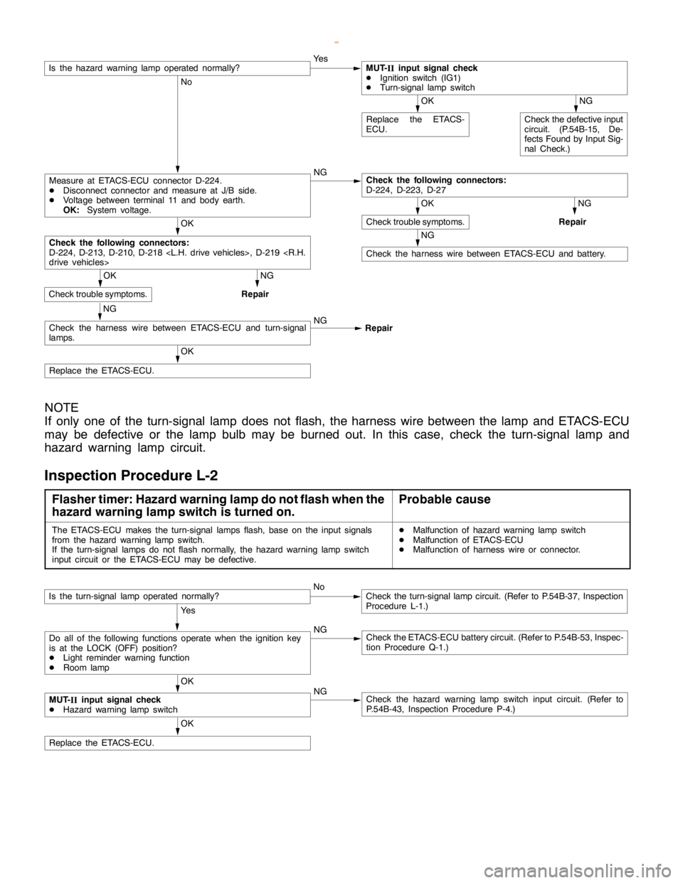
NOTE
If only one of the turn-signal lamp does not flash, the harness wire between the lamp and ETACS-ECU
may be defective or the lamp bulb may be burned out. In this case, check the turn-signal lamp and
hazard warning lamp circuit.
Inspection Procedure L-2
Flasher timer: Hazard warning lamp do not flash when the
hazard warning lamp switch is turned on.Probable cause
The ETACS-ECU makes the turn-signal lamps flash, base on the input signals
from the hazard warninglampswitch.
If the turn-signal lamps do not flash normally, the hazard warninglampswitch
input circuit or the ETACS-ECU may be defective.DMalfunction of hazard warninglampswitch
DMalfunction of ETACS-ECU
DMalfunction of harness wire or connector.
OK
Replace the ETACS-ECU.
NoCheck the turn-signallampcircuit. (Refer to P.54B-37, Inspection
Procedure L-1.)
Ye s
NG
Check the ETACS-ECU battery circuit. (Refer to P.54B-53, Inspec-
tion Procedure Q-1.)
OK
NG
Check the hazard warninglampswitch input circuit. (Refer to
P.54B-43, Inspection Procedure P-4.)MUT-
IIinput signal check
DHazard warninglampswitch
Do all of the following functions operate when the ignition key
is at the LOCK (OFF) position?
DLight reminder warning function
DRoom lamp
Is the turn-signal lamp operated normally?
www.WorkshopManuals.co.uk
Purchased from www.WorkshopManuals.co.uk
Page 1725 of 1839
SWS -TroubleshootingSWS -Troubleshooting54B-39
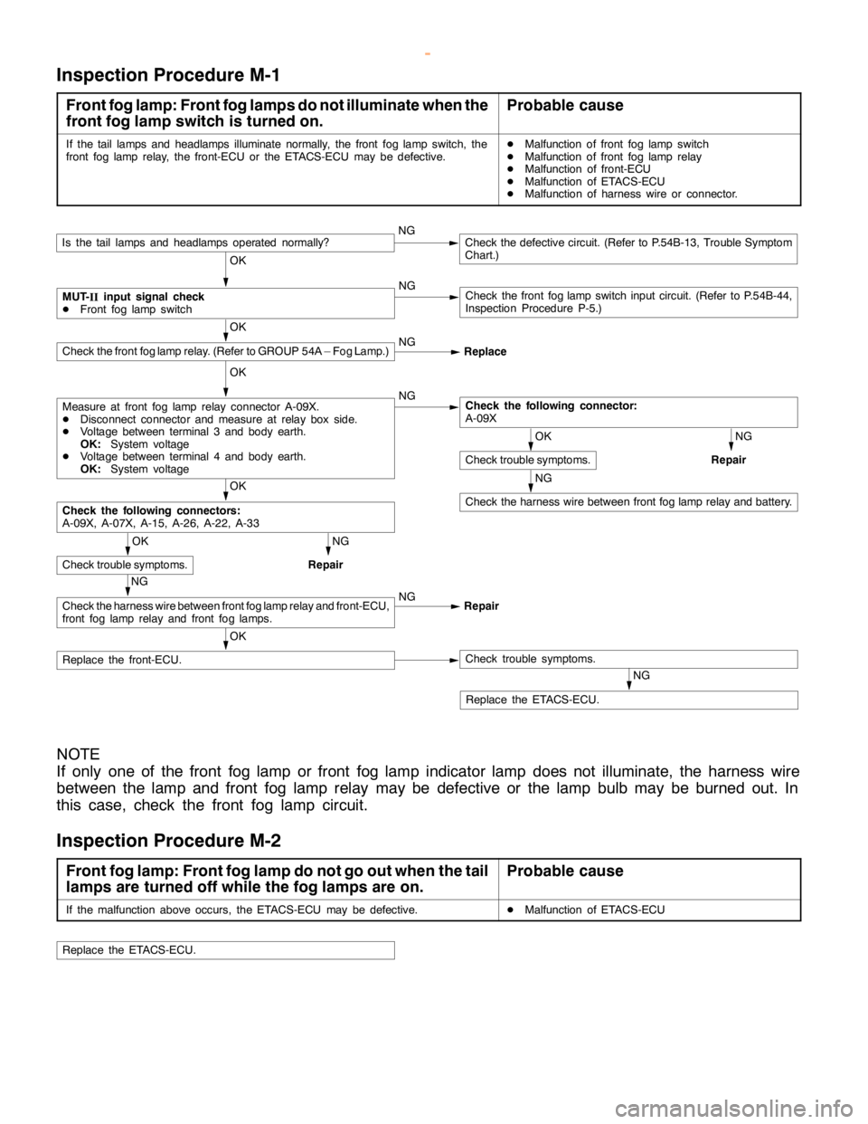
Inspection Procedure M-1
Front fog lamp: Front fog lamps do not illuminate when the
front fog lamp switch is turned on.Probable cause
If the tail lamps and headlamps illuminate normally, the front fog lampswitch, the
front fog lamprelay, the front-ECU or the ETACS-ECU may be defective.DMalfunction of front fog lampswitch
DMalfunction of front fog lamprelay
DMalfunction of front-ECU
DMalfunction of ETACS-ECU
DMalfunction of harness wire or connector.
OK
Replace the front-ECU.Check trouble symptoms.
NGCheck the defective circuit. (Refer to P.54B-13, Trouble Symptom
Chart.)
OK
NG
Check the front foglampswitch input circuit. (Refer to P.54B-44,
Inspection Procedure P-5.)
OK
NG
NG
Repair
NG
Check the harness wire between front foglamprelay and battery.
OK
NG
Repair
NG
Check the harness wire between front foglamprelay and front-ECU,
front fog lamprelay and front fog lamps.NG
Repair
OK
Check trouble symptoms.
Check the following connectors:
A-09X, A-07X, A-15, A-26, A-22, A-33
OK
Check trouble symptoms.
Check the following connector:
A-09XMeasure at front fog lamprelay connector A-09X.
DDisconnect connector and measure at relay box side.
DVoltage between terminal 3 and body earth.
OK:System voltage
DVoltage between terminal 4 and body earth.
OK:System voltage
OK
Check the front foglamprelay. (Refer to GROUP 54A – Fog Lamp.)NG
Replace
MUT-
IIinput signal check
DFront fog lampswitch
Is the tail lamps and headlamps operated normally?
NG
Replace the ETACS-ECU.
NOTE
If only one of the front fog lamp or front fog lamp indicator lamp does not illuminate, the harness wire
between the lamp and front fog lamp relay may be defective or the lamp bulb may be burned out. In
this case, check the front fog lamp circuit.
Inspection Procedure M-2
Front fog lamp: Front fog lamp do not go out when the tail
lamps are turned off while the fog lamps are on.Probable cause
If the malfunction above occurs, the ETACS-ECU may be defective.DMalfunction of ETACS-ECU
Replace the ETACS-ECU.
www.WorkshopManuals.co.uk
Purchased from www.WorkshopManuals.co.uk
Page 1726 of 1839
SWS -Troubleshooting54B-40
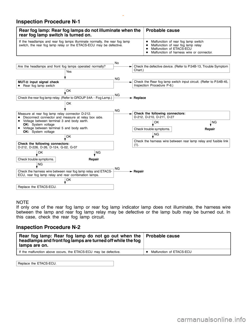
Inspection Procedure N-1
Rear fog lamp: Rear fog lamps do not illuminate when the
rear fog lamp switch is turned on.Probable cause
If the headlamps and rear fog lamps illuminate normally, the rear foglamp
switch, the rear foglamprelay or the ETACS-ECU may be defective.DMalfunction of rear foglampswitch
DMalfunction of rear foglamprelay
DMalfunction of ETACS-ECU
DMalfunction of harness wire or connector.
NoCheck the defective device. (Refer to P.54B-13, Trouble Symptom
Chart.)
Ye s
NG
Check the Rear foglampswitch input circuit. (Refer to P.54B-45,
Inspection Procedure P-6.)
OK
NG
Replace
OK
NG
NG
Repair
NG
Check the harness wire between rearlamprelay and fusible link
(1).
OK
NG
Repair
OK
Check trouble symptoms.
Check the following connectors:
D-212, D-226, D-26, D-124, G-02, G-07
OK
Check trouble symptoms.
Check the following connectors:
D-212, D-210, D-211, D-27Measure at rear foglamprelay connector D-212.
DDisconnect connector and measure at relay box side.
DVoltage between terminal 3 and body earth.
OK:System voltage
DVoltage between terminal 5 and body earth.
OK:System voltage
Check the rear foglamprelay. (Refer to GROUP 54A – Fog Lamp.)
MUT-
IIinput signal check
DRear foglampswitch
Are the headlamps and front fog lamps operated normally?
OK
Replace the ETACS-ECU.
NG
Check the harness wire between rear foglamprelay and ETACS-
ECU, rear foglamprelay and rear combination lamps.NG
Repair
NOTE
If only one of the rear fog lamp or rear fog lamp indicator lamp does not illuminate, the harness wire
between the lamp and rear fog lamp relay may be defective or the lamp bulb may be burned out. In
this case, check the rear fog lamp circuit.
Inspection Procedure N-2
Rear fog lamp: Rear fog lamp do not go out when the
headlamps and front fog lamps are turned off while the fog
lamps are on.Probable cause
If the malfunction above occurs, the ETACS-ECU may be defective.DMalfunction of ETACS-ECU
Replace the ETACS-ECU.
www.WorkshopManuals.co.uk
Purchased from www.WorkshopManuals.co.uk
Page 1727 of 1839
SWS -Troubleshooting54B-41
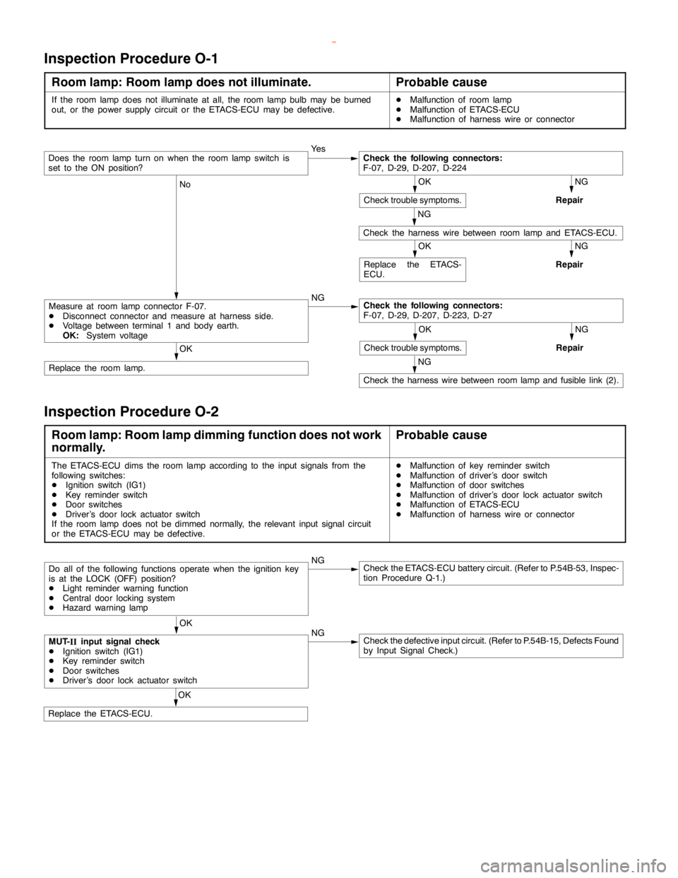
Inspection Procedure O-1
Room lamp: Room lamp does not illuminate.Probable cause
If the room lampdoes not illuminate at all, the roomlamp bulb may be burned
out, or the power supply circuit or the ETACS-ECU may be defective.DMalfunction of room lamp
DMalfunction of ETACS-ECU
DMalfunction of harness wire or connector
Ye s
NG
Repair
NG
No
NG
OK
Replace the room lamp.
NG
Repair
NG
Check the harness wire between roomlamp and fusiblelink (2).
OK
Replace the ETACS-
ECU.
NG
Repair
OK
Check trouble symptoms.
Check the following connectors:
F-07, D-29, D-207, D-223, D-27Measure at room lampconnector F-07.
DDisconnect connector and measure at harness side.
DVoltage between terminal 1 and body earth.
OK:System voltage
Check the harness wire between roomlamp and ETACS-ECU.
OK
Check trouble symptoms.
Check the following connectors:
F-07, D-29, D-207, D-224Does the roomlampturn on when the roomlampswitch is
set to the ON position?
Inspection Procedure O-2
Room lamp: Room lamp dimming function does not work
normally.Probable cause
The ETACS-ECU dims the roomlamp according to the inputsignals from the
following switches:
DIgnition switch (IG1)
DKey reminder switch
DDoor switches
DDriver’s door lock actuator switch
If the room lampdoes not bedimmed normally, the relevant input signalcircuit
or the ETACS-ECU may be defective.DMalfunction of key reminder switch
DMalfunction of driver’s door switch
DMalfunction of door switches
DMalfunction of driver’s door lock actuator switch
DMalfunction of ETACS-ECU
DMalfunction of harness wire or connector
NGCheck the ETACS-ECU battery circuit. (Refer to P.54B-53, Inspec-
tion Procedure Q-1.)
OK
NG
Check the defective input circuit. (Refer to P.54B-15, Defects Found
by Input Signal Check.)
OK
Replace the ETACS-ECU.
MUT-
IIinput signal check
DIgnition switch (IG1)
DKey reminder switch
DDoor switches
DDriver’s door lock actuator switch
Do all of the following functions operate when the ignition key
is at the LOCK (OFF) position?
DLight reminder warning function
DCentral door locking system
DHazard warninglamp
www.WorkshopManuals.co.uk
Purchased from www.WorkshopManuals.co.uk