2000 MITSUBISHI MONTERO heater
[x] Cancel search: heaterPage 46 of 1839

3 MSB-00E00-505
3. Details:
Contents of Attachment are to be added to GROUP 00 (GENERAL).
PRECAUTIONS BEFORE SERVICE
LEARNING FUNCTION OF GDI ENGINE
1. Purpose
On the GDI engine equipped cars, when replacement of the ECU (for engine control) or resetting
of the battery* has been performed, an idle learning function of the ECU (for engine control) will
be required.
The idle learning function will be completed by running the engine at idle by the following procedure.
NOTE:
*: Disconnection of ECU (for engine control) battery backup power supply (disconnection of battery
terminals or ECU connectors)
2. Idle Learning Procedure
(1) Start the engine, and warm up the engine until its coolant temperature reaches 85°C or higher.
When the engine coolant temperature is 85°C or higher, you have only to turn the ignition
switch to the ON position.
(2) Turn the ignition switch to the LOCK (OFF) position, and stop the engine.
(3) After lapse of ten or more seconds, restart the engine.
(4) Run the engine at idle for ten minutes under the following conditions.
DTransmission: Neutral (P range for automatic transmission)
DAir conditioner and heater: Not operational
DEngine coolant temperature: 83°C or higher
(5) Stop the engine.
(6) Restart the engine, and run it at idle for ten minutes under the following condition.
DTransmission: Neutral (P range for automatic transmission)
DAir conditioner: Operational (Temperature set at “maximum cool”, fan at high speed, and
windows fully opened)
DEngine coolant temperature: 83°C or higher
(7) Repeat steps (5) and (6).
NOTE:
1) When the atmospheric temperature is 20°C or more and the air conditioner has continuously
been operated, step (7) may be omitted.
2) During idling operation of the engine in steps (4) and (6), when engine operation switches
from lean operation to stoichiometric operation, engine stall can occur. In this case, clean the
throttle body (throttle valve) thoroughly, and then repeat step (1) and the subsequent steps.
www.WorkshopManuals.co.uk
Purchased from www.WorkshopManuals.co.uk
Page 226 of 1839

GDI -Troubleshooting
FREEZE FRAME DATA
When the engine-ECU detects a malfunction and stores a
diagnosis code, it also stores a current status of the engine.
This function is called “Freeze frame data.” By analyzing
this “freeze frame” data with the MUT-II, an effective
troubleshooting can be performed.
Data itemUnit
Engine coolant temperature sensor_C
Engine speedr/min
Vehicle speedkm/h
Long-term fuel compensation (long-term
fuel trim)%
Short-term fuel compensation (short-term
fuel trim)%
Fuel control condi-Open loopOL
tion
Closed loopCL
Open loop owing to
drive conditionOL-DRV.
Open loop owing to
system malfunctionOL-SYS.
Closed loop based
on one oxygen sen-
sorCL-H02S
Calculation load value%
Diagnosis code during data recording-
NOTE
If malfunctions have been detected in multiple systems, store
one malfunction only, which has been detected first.
READINESS TEST STATUS
The engine-ECU monitors the following main diagnosis items,
judges if these items are in good condition or not, and the
stores its history. This history can be read out by using MUT-II.
(If the ECU has judged a item before, the MUT-II displays
“Complete.”)
In addition, if diagnosis codes are erased or the battery
cable is disconnected, this history will also be erased (the
memory will be reset).
DCatalyst: P0420
DOxygen sensor: P0130
DOxygen sensor heater: P0135, P0141
www.WorkshopManuals.co.uk
Purchased from www.WorkshopManuals.co.uk
Page 229 of 1839

GDI -Troubleshooting
INSPECTION CHART FOR DIAGNOSIS CODES
Code No.Diagnosis itemReference page
P0100Air flow sensor system13A-17
P0105Barometric pressure sensor system13A-19
P0110Intake air temperature sensor system13A-21
P0115Engine coolant temperature sensor system13A-22
P0120LThrottle position sensor (1st channel) system13A-25
P0125Feedback system13A-27
P0130Oxygen sensor (front) system
P0135Oxygen sensor heater (front) system
P0136Oxygen sensor (rear) system
P0141Oxygen sensor heater (rear) system
P0170Abnormal fuel system13A-34
P0190LAbnormal fuel pressure13A-36
P0201No.1 injector system13A-38
P0202No.2 injector system13A-40
P0203No.3 injector system13A-42
P0204No.4 injector system13A-44
P0205No.5 injector system13A-46
P0206No.6 injector system13A-48
P0220LAccelerator pedal position sensor (1st channel) system13A-50
P0225LThrottle position sensor (2nd channel) system13A-52
P0300LIgnition coil (power transistor) system13A-53
P0301No.1 cylinder misfire detected.13A-55
P0302No.2 cylinder misfire detected.13A-55
P0303No.3 cylinder misfire detected.13A-55
P0304No.4 cylinder misfire detected.13A-55
P0305No.5 cylinder misfire detected.13A-55
P0306No.6 cylinder misfire detected.13A-55
P0325Detonation sensor system13A-56
P0335Crank angle sensor system13A-56
P0340Camshaft position sensor system13A-58
P0403EGR valve system13A-60
P0420Catalyst malfunction13A-61
www.WorkshopManuals.co.uk
Purchased from www.WorkshopManuals.co.uk
Page 244 of 1839

GDI -Troubleshooting
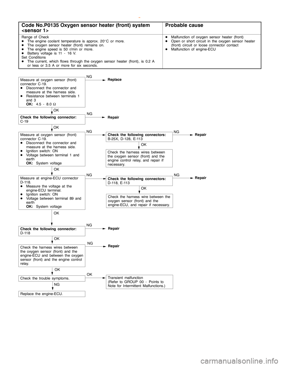
Code No.P0135 Oxygen sensor heater (front) system
Range of Check
DThe engine coolant temperature is approx. 20_C or more.
DThe oxygen sensor heater (front) remains on.
DThe enginespeed is 50 r/min or more.
DBattery voltage is 11 - 16 V.
Set Conditions
DThe current, which flows through the oxygen sensor heater (front), is 0.2 A
or less or 3.5 A or more for six seconds.DMalfunction of oxygen sensor heater (front)
DOpen or short circuit in the oxygen sensor heater
(front) circuit or loose connector contact
DMalfunction of engine-ECU
OK
Check the harness wire between the
oxygen sensor (front) and the
engine-ECU, and repair if necessary.
Repair
OK
Measure at engine-ECU connector
D-118.
DMeasure the voltage at the
engine-ECU terminal.
DIgnition switch: ON
DVoltage between terminal 89 and
earth
OK:
System voltageNGCheck the following connectors:
D-118, E-113NG
OK
Check the harness wires between
the oxygen sensor (front) and the
engine controlrelay, and repair if
necessary.
Measure at oxygen sensor (front)
connector C-19.
DDisconnect the connector and
measure at the harness side.
DResistance between terminals 1
and 3
OK:
4.5 - 8.0WNG
Replace
Repair
OK
Measure at oxygen sensor (front)
connector C-19.
DDisconnect the connector and
measure at the harness side.
DIgnition switch: ON
DVoltage between terminal 1 and
earth
OK:
System voltageNGCheck the following connectors:
B-25X, D-128, E-113NG
OK
Check the following connector:
C-19NG
Repair
OK
Check the trouble symptoms.OKTransient malfunction
(Refer to GROUP 00 - Points to
Note for Intermittent Malfunctions.) NG
Replace the engine-ECU.
OK
Check the following connector:
D-118NG
Repair
OK
Check the harness wires between
the oxygen sensor (front) and the
engine-ECU and between the oxygen
sensor (front) and theengine control
relay.NG
Repair
www.WorkshopManuals.co.uk
Purchased from www.WorkshopManuals.co.uk
Page 247 of 1839

GDI -Troubleshooting
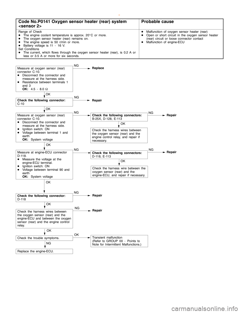
Code No.P0141 Oxygen sensor heater (rear) system
Range of Check
DThe engine coolant temperature is approx. 20_C or more.
DThe oxygen sensor heater (rear) remains on.
DThe enginespeed is 50 r/min or more.
DBattery voltage is 11 - 16 V.
Set Conditions
DThe current, which flows through the oxygen sensor heater (rear), is 0.2 A or
less or 3.5 A or more for six seconds.DMalfunction of oxygen sensor heater (rear)
DOpen or short circuit in the oxygen sensor heater
(rear) circuit or loose connector contact
DMalfunction of engine-ECU
OK
Check the harness wire between the
oxygen sensor (rear) and the
engine-ECU, and repair if necessary.
Repair
OK
Measure at engine-ECU connector
D-118.
DMeasure the voltage at the
engine-ECU terminal.
DIgnition switch: ON
DVoltage between terminal 90 and
earth
OK:
System voltageNGCheck the following connectors:
D-118, E-113NG
OK
Check the harness wires between
the oxygen sensor (rear) and the
engine controlrelay, and repair if
necessary.
Measure at oxygen sensor (rear)
connector C-10.
DDisconnect the connector and
measure at the harness side.
DResistance between terminals 1
and 3
OK:
4.5 - 8.0WNG
Replace
Repair
OK
Measure at oxygen sensor (rear)
connector C-10.
DDisconnect the connector and
measure at the harness side.
DIgnition switch: ON
DVoltage between terminal 1 and
earth
OK:
System voltageNGCheck the following connectors:
B-25X, D-128, E-113NG
OK
Check the following connector:
C-10NG
Repair
OK
Check the trouble symptoms.OKTransient malfunction
(Refer to GROUP 00 - Points to
Note for Intermittent Malfunctions.) NG
Replace the engine-ECU.
OK
Check the following connector:
D-118NG
Repair
OK
Check the harness wires between
the oxygen sensor (rear) and the
engine-ECU and between the oxygen
sensor (rear) and theengine control
relay.NG
Repair
www.WorkshopManuals.co.uk
Purchased from www.WorkshopManuals.co.uk
Page 328 of 1839

GDI -Troubleshooting
Terminal
No.Normal condition Check requirements (engine condition) Check item
63Stop lamp switchDepress the brake pedal.System voltage
Release the brake pedal.0-3V
65A/C switch (2nd channel)Refer to GROUP 55 - Troubleshooting “Check at the A/C-ECU
terminal, engine-ECU output terminals.”
66Clutch switchDepress the clutch pedal.0-3V
Release the clutch pedal.System voltage
68Ignition switch-STEngine: Cranking8V or more
71Oxygen sensor (front)Engine: Warm up, and then hold the
engine speed at 2,500r/min (Use a
digital voltmeter).0«0.8 V alternates.
76Air flow sensor reset signalEngine: Idling0-1V
Engine: 3,000 r/min6-9V
78Throttle position sensor
(2nd channel)Ignition switch:
ONRelease the
accelerator pedal.4.5 - 5.5 V
Depress the
accelerator pedal
fully.0.4 - 0.6 V
79Accelerator pedal position
switchIgnition switch:
ONRelease the
accelerator pedal.0-1V
Depress the
accelerator pedal
fully.4V or more
80Vehicle speed sensorDIgnition switch: ON
DMove the vehicle forward.0«system voltage
alternates.
83A/C switch (1st channel)Engine: IdlingA/C switch: OFF0-3V
A/C switch: ON
(Compressor is
operating)System voltage
88Small lamp switchLighting switch: OFF0-3V
Lighting switch: ON (Taillamp: ON)System voltage
89Oxygen sensor heaterEngine: Idling0-3V
(front)
Engine: 3,500 r/minSystem voltage
90Oxygen sensor heaterEngine: Idling0-3V
(rear)
Engine: 3,500 r/minSystem voltage
92Fuel pressure sensorEngine: Idling0.3 - 4.7 V
www.WorkshopManuals.co.uk
Purchased from www.WorkshopManuals.co.uk
Page 476 of 1839

Page 527 of 1839

DIESEL FUEL <4M4> -Troubleshooting13C-36
Item
No.Reference
page Code No.
or inspec-
tion proce-
dure No. Value to be
determined
as normal Inspection conditions Check item
58NeutralIgnition switch: ONN, P rangeN, P––
switchNone of the aboveD, R
60Fuel cut
relayIgnition switch: ON®OFF afterwards for a
certain period of timeON––
None of the aboveOFF
61EGR controlTurning off EGR quicklyON––
solenoid
valve No. 2None of the aboveOFF
62AT/MTIgnition switch: ONVehicles with A/TA/T––
switchVehicles with M/TM/T
68A/C switch 2A/C: Under high load or low loadON––
A/C: OFF or under medium loadOFF
69Warm up
switchDWarm up switch: ON
DHeater temperature setting: Maximum
DEngine coolant temperature: 90_C or lower
DBlower fan: ONON––
None of the aboveOFF
70PTC heaterDWarm up switch: ON
DHeater temperature setting: Maximum
DEngine coolant temperature: 65_Cto75_C
or lower
DBlower fan: ONON––
None of the aboveOFF
71PowerPower steering switch: ONON––
steering
switchPower steering switch: OFFOFF
www.WorkshopManuals.co.uk
Purchased from www.WorkshopManuals.co.uk