2000 MITSUBISHI MONTERO change key battery
[x] Cancel search: change key batteryPage 1281 of 1839

ABS <4WD> -Troubleshooting35B-18
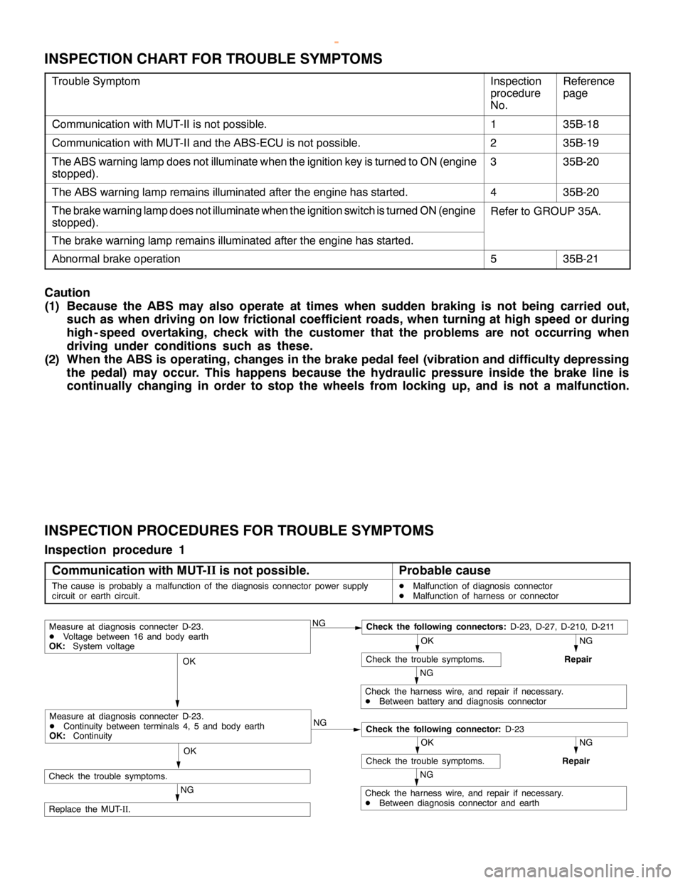
INSPECTION CHART FOR TROUBLE SYMPTOMS
Trouble SymptomInspection
procedure
No.Reference
page
Communication with MUT-II is not possible.135B-18
Communication with MUT-II and the ABS-ECU is not possible.235B-19
The ABS warning lamp does not illuminate when the ignition key is turned to ON (engine
stopped).335B-20
The ABS warning lamp remains illuminated after the engine has started.435B-20
The brake warning lamp does not illuminate when the ignition switch is turned ON (engine
stopped).Refer to GROUP 35A.
The brake warning lamp remains illuminated after the engine has started.
Abnormal brake operation535B-21
Caution
(1) Because the ABS may also operate at times when sudden braking is not being carried out,
such as when driving on low frictional coefficient roads, when turning at high speed or during
high - speed overtaking, check with the customer that the problems are not occurring when
driving under conditions such as these.
(2) When the ABS is operating, changes in the brake pedal feel (vibration and difficulty depressing
the pedal) may occur. This happens because the hydraulic pressure inside the brake line is
continually changing in order to stop the wheels from locking up, and is not a malfunction.
INSPECTION PROCEDURES FOR TROUBLE SYMPTOMS
Inspection procedure 1
Communication with MUT-II
is not possible.
Probable cause
The cause is probably a malfunction of the diagnosis connector power supply
circuit or earth circuit.DMalfunction of diagnosis connector
DMalfunction of harness or connector
NGCheck the following connectors:D-23, D-27, D-210, D-211
NG
Repair
OK
Check the trouble symptoms.
NG
Check the harness wire, and repair if necessary.
DBetween battery and diagnosis connector
OK
NG
NG
Repair
OK
Check the trouble symptoms.
NG
Check the harness wire, and repair if necessary.
DBetween diagnosis connector and earth
OK
NG
Replace the MUT-
II.
Measure at diagnosis connecter D-23.
DVoltage between 16 and body earth
OK:System voltage
Check the following connector:D-23
Measure at diagnosis connecter D-23.
DContinuity between terminals 4, 5 and body earth
OK:Continuity
Check the trouble symptoms.
www.WorkshopManuals.co.uk
Purchased from www.WorkshopManuals.co.uk
Page 1632 of 1839

CHASSIS ELECTRICAL -Clock or Center Display54A-62
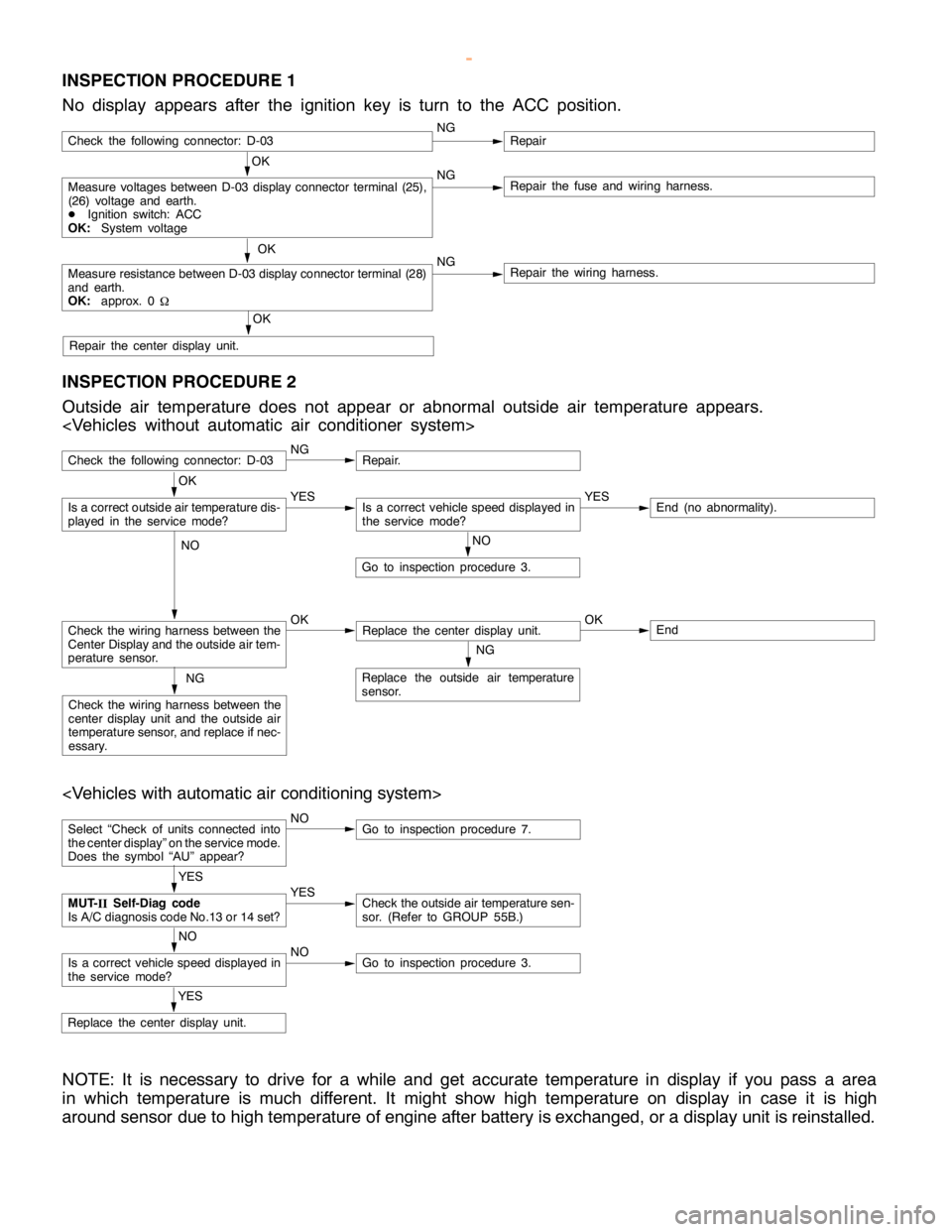
INSPECTION PROCEDURE 1
No display appears after the ignition key is turn to the ACC position.
OK
Measure voltages between D-03 display connector terminal (25),
(26) voltage and earth.
DIgnition switch: ACC
OK:System voltageNGRepair the fuse and wiring harness.
OK
Measure resistance between D-03 display connector terminal (28)
and earth.
OK:approx. 0
WNGRepair the wiring harness.
OK
Repair the center display unit.
Check the following connector: D-03NGRepair
INSPECTION PROCEDURE 2
Outside air temperature does not appear or abnormal outside air temperature appears.
Check the following connector: D-03NGRepair.
NO
Go to inspection procedure 3.
Check the wiring harness between the
Center Display and the outside air tem-
perature sensor.OKReplace the center display unit.OKEnd
NG
Replace the outside air temperature
sensor.NG
Check the wiring harness between the
center display unit and the outside air
temperature sensor, and replace if nec-
essary.
OK
Is a correct outside air temperature dis-
played in the servicemode?YESIs a correct vehicle speed displayed in
the servicemode?YESEnd (no abnormality).
NO
Select “Check of units connected into
the center display” on the service mode.
Does the symbol “AU” appear?NOGo to inspection procedure 7.
YES
Replace the center display unit.
YES
MUT-
IISelf-Diag code
Is A/C diagnosis code No.13 or 14 set?YESCheck the outside air temperature sen-
sor. (Refer to GROUP 55B.)
NO
Is a correct vehicle speed displayed in
the servicemode?NOGo to inspection procedure 3.
NOTE: It is necessary to drive for a while and get accurate temperature in display if you pass a area
in which temperature is much different. It might show high temperature on display in case it is high
around sensor due to high temperature of engine after battery is exchanged, or a display unit is reinstalled.
www.WorkshopManuals.co.uk
Purchased from www.WorkshopManuals.co.uk
Page 1691 of 1839

SWS -General InformationSWS -General Information54B-5
HEADLAMP WASHER
If the headlamp washer switch at the steering
column is placed in the ON position when the ignition
switch is in the ACC or ON position and theheadlamp switch is in the ON position, the headlamp
washer drive signal is turned ON for 0.5 second.
IGNITION KEY HOLE ILLUMINATION LAMP
When the ignition switch is turned to LOCK (OFF) or
ACC position with the driver’s door opened, the
ignition key hole illumination lamp is illuminated.
If the door is closed in that state, the lamp goes out
after 30 seconds. Vehicles with keyless entrysystem, it illuminates for 30 seconds after the
ignition key is removed. In either case the lamp goes
out when the ignition switch is turned to ON position.
HEADLAMP
Headlamp Automatic Shutdown Function
If the ignition switch is turned to LOCK (OFF) or
ACC position, when the headlamps are on, the
headlamps will be switched off in three minutes.
If the driver’s door is opened within that three-minute
period, the headlamps will be switched off
automatically. This prevents the battery from
discharged.
In addition, if the headlamps are turned on when
the ignition switch is at LOCK (OFF) or ACC position,
the headlamps will not be switched off.Headlamp Dimmer Switch Automatic Reset
Function
This function allows the dimmer switch to be reset
to the low-beam position whenever the headlamp
switch is turned ON.
Daytime Running Lamp (DRL) Function
If the ignition switch is turned to ON when the
headlamps and tail lamps are off, the headlamps
(low-beam) and tail lamps turn on.
FLASHER TIMER
Turn-signal Lamp
When the ignition switch is turned to ON position
and turn-signal lamp switch is placed in the ON
position for right or left turn signaling, the system
generates turn-signal lamp drive signals (flashing
signals).
The system also notifies of a blown turn-signal lamp
bulb by shortening the flashing intervals of the
corresponding indicator lamp.Hazard Warning Lamp
The system detects a change from ON to OFF
of the hazard lamp input signal and activates the
hazard lamps if they are not in operation or
deactivates the lamps if they are operating (reversal
of state between activation and deactivation).
FRONT FOG LAMP
If the front fog lamp switch is turned ON at the
condition that the headlamp or the tail lamp is turned
ON (including the illumination by the automatic
lighting function), the front fog lamp is turned ON.Whenever the tail lamps are turned on at the next
time, the front fog lamps will always be off regardless
of the switch positions. In addition, if the tail lamp
is switched off by the automatic lighting system,
the front fog lamp will also be switched off. However,
the front fog lamp will be illuminated when the tail
lamp is switched on.
www.WorkshopManuals.co.uk
Purchased from www.WorkshopManuals.co.uk