2000 MITSUBISHI MONTERO air bleeding
[x] Cancel search: air bleedingPage 168 of 1839

ENGINE <4M4> -Cylinder Head Gasket11C-27
CYLINDER HEAD GASKET
REMOVAL AND INSTALLATION
Pre-removal and Post-installation Operation
DEngine Coolant Drain and Refill
(Refer to GROUP 14 - On-vehicle Service.)
DEngine Oil Check andRefill
(Refer to GROUP 12 - On-vehicle Service.)
DFuel Line Air-bleeding
(Refer to GROUP 13C - On-vehicle Service.)
DDrive Belt TensionCheck and Adjustment
(Refer to P.11C-5.)
(Refer to P.11C-20.)
DCooling Fan and Fan Clutch Assembly Removal and
Installation (Refer to GROUP 14.)
DIntake Manifold Removal and Installation
(Refer to GROUP15.)
DTurbocharger Removal and Installation
(Refer to GROUP15.)
DExhaust Manifold Removal and Installation
(Refer to GROUP15.)
www.WorkshopManuals.co.uk
Purchased from www.WorkshopManuals.co.uk
Page 519 of 1839

DIESEL FUEL <4M4> -Troubleshooting13C-28
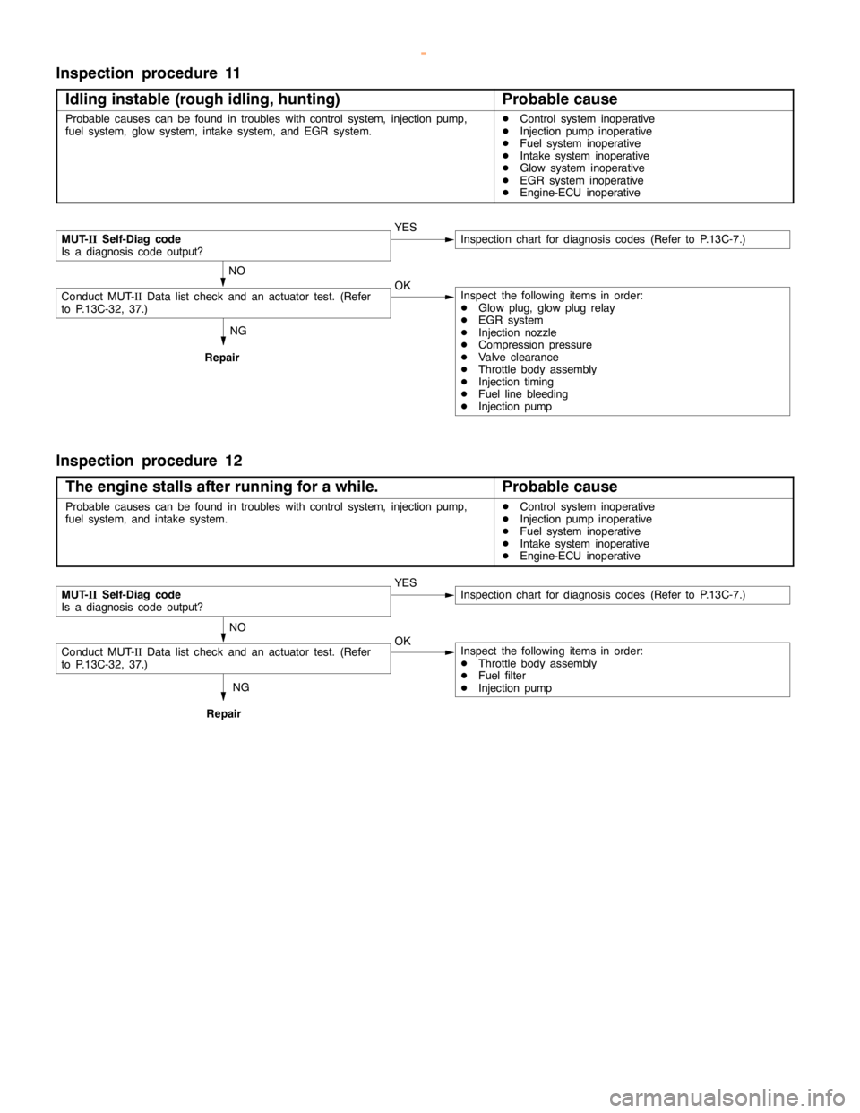
Inspection procedure 11
Idling instable (rough idling, hunting)
Probable cause
Probable causes can be found in troubles with control system, injectionpump,
fuel system, glow system, intake system, and EGR system.DControl system inoperative
DInjection pump inoperative
DFuel system inoperative
DIntake system inoperative
DGlow system inoperative
DEGR system inoperative
DEngine-ECU inoperative
NG
Repair
MUT-
IISelf-Diag code
Is a diagnosis code output?YESInspection chart for diagnosis codes (Refer to P.13C-7.)
NO
Conduct MUT-IIData list check and an actuator test. (Refer
to P.13C-32, 37.)OKInspect the following items in order:
DGlow plug, glowplugrelay
DEGR system
DInjection nozzle
DCompression pressure
DValve clearance
DThrottle body assembly
DInjection timing
DFuel line bleeding
DInjection pump
Inspection procedure 12
The engine stalls after running for a while.
Probable cause
Probable causes can be found in troubles with control system, injectionpump,
fuel system, and intake system.DControl system inoperative
DInjection pump inoperative
DFuel system inoperative
DIntake system inoperative
DEngine-ECU inoperative
NG
Repair
MUT-
IISelf-Diag code
Is a diagnosis code output?YESInspection chart for diagnosis codes (Refer to P.13C-7.)
NO
Conduct MUT-IIData list check and an actuator test. (Refer
to P.13C-32, 37.)OKInspect the following items in order:
DThrottle body assembly
DFuel filter
DInjection pump
www.WorkshopManuals.co.uk
Purchased from www.WorkshopManuals.co.uk
Page 643 of 1839

DIESEL FUEL <4D5-stepIII>-Troubleshooting13E-33
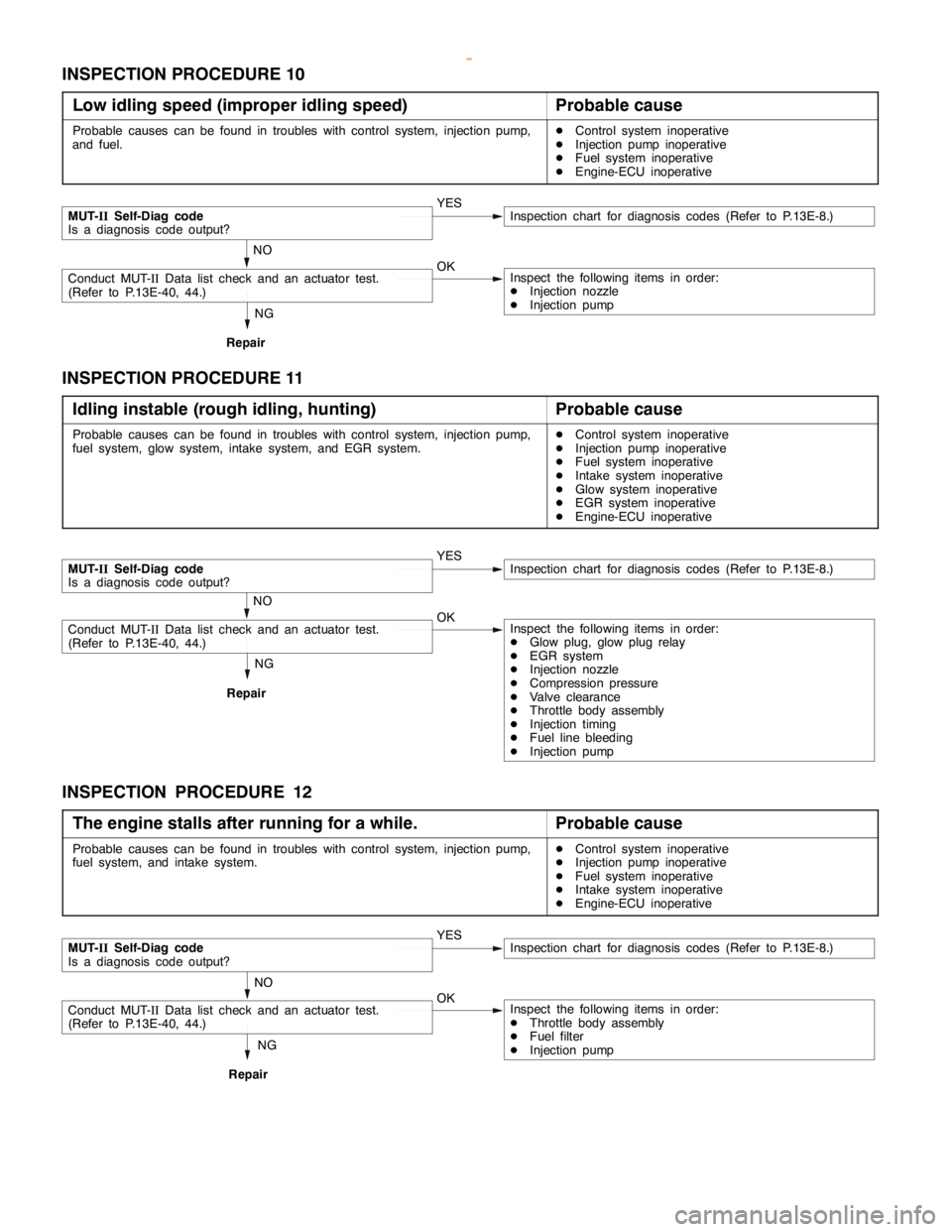
INSPECTION PROCEDURE 10
Low idling speed (improper idling speed)
Probable cause
Probable causes can be found in troubles with control system, injection pump,
and fuel.DControl system inoperative
DInjection pump inoperative
DFuel system inoperative
DEngine-ECU inoperative
NG
Repair
MUT-IISelf-Diag code
Is a diagnosis code output?YESInspection chart for diagnosis codes (Refer to P.13E-8.)
NO
Conduct MUT-IIData list check and an actuator test.
(Refer to P.13E-40, 44.)OKInspect the following items in order:
DInjection nozzle
DInjection pump
INSPECTION PROCEDURE 11
Idling instable (rough idling, hunting)
Probable cause
Probable causes can be found in troubles with control system, injection pump,
fuel system, glow system, intake system, and EGR system.DControl system inoperative
DInjection pump inoperative
DFuel system inoperative
DIntake system inoperative
DGlow system inoperative
DEGR system inoperative
DEngine-ECU inoperative
NG
Repair
MUT-IISelf-Diag code
Is a diagnosis code output?YESInspection chart for diagnosis codes (Refer to P.13E-8.)
NO
Conduct MUT-IIData list check and an actuator test.
(Refer to P.13E-40, 44.)OKInspect the following items in order:
DGlow plug, glow plug relay
DEGR system
DInjection nozzle
DCompression pressure
DValve clearance
DThrottle body assembly
DInjection timing
DFuel line bleeding
DInjection pump
INSPECTION PROCEDURE 12
The engine stalls after running for a while.
Probable cause
Probable causes can be found in troubles with control system, injection pump,
fuel system, and intake system.DControl system inoperative
DInjection pump inoperative
DFuel system inoperative
DIntake system inoperative
DEngine-ECU inoperative
NG
Repair
MUT-IISelf-Diag code
Is a diagnosis code output?YESInspection chart for diagnosis codes (Refer to P.13E-8.)
NO
Conduct MUT-IIData list check and an actuator test.
(Refer to P.13E-40, 44.)OKInspect the following items in order:
DThrottle body assembly
DFuel filter
DInjection pump
www.WorkshopManuals.co.uk
Purchased from www.WorkshopManuals.co.uk
Page 1165 of 1839

POWER PLANT MOUNT - No.1 Crossmember32-7
No.1 CROSSMEMBER
REMOVAL AND INSTALLATION
Caution
1. Before removing the steering wheel and airbag module assembly, always refer to GROUP 52B
- Service Precautions, Airbag Module and Clock Spring. Also, set the front wheels so that
they are facing straight forward, and remove the ignition key. If you fail to do this, the SRS
clock spring will be damaged, causing the SRS airbag to be inoperative and serious injury.
2. *: Indicates parts which should be initially tightened, and then fully tightened after placing
the vehicle horizontally and loading the full weight of the engine on the vehicle body.
Pre-removal Operation
DUnder Cover Removal
DDrive Shaft Removal
(Refer to GROUP 26.)
DDifferential Carrier and No.2 Crossmember
Assembly Removal (Refer to GROUP 26 -
Freewheel Assembly and Differential Carrier.)
DUpper Arm Removal
(Refer to GROUP 33A.)
DLower Arm Removal
(Refer to GROUP 33A.)
DStabilizer Bar Removal
(Refer to GROUP 33A.)
DEngine Oil Cooler Removal<6G7>
(Refer to GROUP 12.)
DAir Cleaner Removal<4M4>
(Refer to GROUP 15.)
DIntercooler Removal<4M4>
(Refer to GROUP 15.)
DEngine Cover Removal
(Refer to GROUP 11A - Timing Belt.)
DRadiator Removal
(Refer to GROUP 14.)
DPower Steering Fluid Draining
(Refer to GROUP 37A - On - vehicle Service.)Post - installation Operations
DDifferential Carrier and No.2 Crossmember
Assembly Installation (Refer to GROUP 26 -
Freewheel Assembly and Differential Carrier.)
DDrive Shaft Installation
(Refer to GROUP 26.)
DLower Arm Installation
(Refer to GROUP 33A.)
DUpper Arm Installation
(Refer to GROUP 33A.)
DStabilizer Bar Installation
(Refer to GROUP 33A.)
DAir Cleaner Installation<4M4>
(Refer to GROUP 15.)
DIntercooler Installation<4M4>
(Refer to GROUP 15.)
DRadiator Installation
(Refer to GROUP 14.)
DEngine Oil Cooler Installation
(Refer to GROUP 12.)
DPower Steering Fluid Supplying
(Refer to GROUP 37A - On - vehicle Service.)
DPower Steering Fluid Line Bleeding
(Refer to GROUP 37A - On - vehicle Service.)
DPress the dust cover with a finger tocheck whether
the dust cover is cracked or damaged.
DChecking Steering Wheel Position with Wheels
StraightAhead
DFront Wheel AlignmentCheck and Adjustment
(Refer to GROUP 37A - On - vehicle Service.)
DUnder Cover Installation
DEngine Cover Installation
(Refer to GROUP 11A - Timing Belt.)
www.WorkshopManuals.co.uk
Purchased from www.WorkshopManuals.co.uk
Page 1235 of 1839

BASIC BRAKE SYSTEM -On-vehicle ServiceBASIC BRAKE SYSTEM -On-vehicle Service35A-27
BLEEDING
Caution
Specified brake fluid: DOT3 or DOT4
1. Always use the specified brake fluid. Avoid using
a mixture of the specified brake fluid and other fluid.
2. Maintain the fluid reservoir level between the MIN
and MAX marks during the air bleeding.
3. Do not depress the brake pedal hard during the air
bleeding (normal air bleeding) to prevent the pump
motor from operating frequently.
4. After the air bleeding, check that the brake dragging
does not become stronger.
5. If the pedal is depressed with the reservoir cap
removed, the brake fluid may overflow. Do not depress
the brake pedal while the fluid is being added.
NORMAL AIR BLEEDING
After the front brake or the rear brake is removed and installed,
some fluid may remain in the hydraulic brake booster (HBB)
reservoir. In this case, bleed air from the brake caliper.
HBB SYSTEM AIR BLEEDING
If all the brake fluid inside the reservoir is drained due to
the removal and installation of the HBB, bleed air as follows:
Air bleeding from front brake system
1. Turn the ignition switch to the LOCK (OFF) position. Bleed
air from the front brake calipers (right and left) by pumping
the brake pedal.
Pump motor operation
2. Turn the ignition switch ON, and operate the pump motor.
If the pump motor is running free, supply the brake fluid
into the pump motor by depressing the brake pedal three
or four times.
Air bleeding from accumulator system
3. After the pump motor stopped, depress the brake pedal
three or four times with the ignition switch ON. Then
observe the brake fluid in the reservoir. If the brake fluid
looks whitish, wait for a few minutes until it becomes
clear.
4. Repeat step 3 until the brake fluid becomes clear.
www.WorkshopManuals.co.uk
Purchased from www.WorkshopManuals.co.uk
Page 1285 of 1839

ABS <4WD> -Troubleshooting35B-22
DATA LIST REFERENCE TABLE
The following ECU input data items can be read using the MUT-II
.
(1) When system is normal
Item
No.Check itemInspection conditionsNormal condi-
tion
11Front - right wheel
speedWhen vehicle is being drivenSpeedometer
display and
12Front - left wheel
speedMUT-IIdisplay
are identical.
13Rear - right wheel
speed
14Rear - left wheel
speed
16System voltageIgnition switch: ON6.5 - 22.3 V
26Center differential
lock switchIgnition switch: ONTransfer selector lever position:
2H, 4HOFF
Transfer selector lever position:
4HLc, 4LLcON
27Rear differential lock
switchIgnition switch: ONOFF
32G sensorD
Ignition switch: ON
D
When vehicle is stationary (level)2.4 - 2.6 V
When vehicle is being driven1.0 - 4.0 V
33Stop lampIgnition switch: ONWhen brake pedal is depressedON
SwitchWhen brake pedal is releasedOFF
(2) When system is interrupted by the ECU
When the diagnosis function has caused the operation of the ABS-ECU to be stopped, the
MUT-II
display data may be different from the actual condition.
ACTUATOR TEST TABLE
The following actuators can be force-driven using the MUT-II
.
NOTE
(1) Actuator tests cannot be carried out when the operation of the ABS-ECU has been stopped by
the fail-safe function.
(2) Actuator tests can only be carried out while the vehicle is stopped.
ACTUATOR TEST SPECIFICATIONS
Item No.Check itemDrive Contents
01FR wheel solenoid valveHBB select solenoid valves and control solenoid valves for the
02FL wheel solenoid valverespective channel
03RR wheel solenoid valve
04RL wheel solenoid valve
27Air bleeding (1)HBB select solenoid valves and control solenoid valve OUT (FR, FL)
28Air bleeding (2)HBB control solenoid valve OUT (RR, RL)
www.WorkshopManuals.co.uk
Purchased from www.WorkshopManuals.co.uk
Page 1310 of 1839

37A-1
STEERING
CONTENTS
GENERAL INFORMATION 2..................
SERVICE SPECIFICATIONS 5.................
LUBRICANTS 5..............................
SEALANT AND ADHESIVE 5.................
SPECIAL TOOLS 6..........................
ON-VEHICLE SERVICE 8.....................
Steering Wheel Free Play Check 8..............
Steering Angle Check 8........................
Tie Rod End Ball Joint Starting Torque Check 8..
Stationary Steering Effort Check 9...............
Steering Wheel Returnability Check 9............
Oil Pump Belt Tension Check <6G7,4D5> 9......Power Steering Fluid Level Check 10............
Power Steering Fluid Replacement 10...........
Power Steering System Bleeding 10.............
Oil Pump Pressure Test 11.....................
Power Steering Oil Pressure Switch Check
<6G7,4M4> 12.................................
Ball Joint Dust Cover Check 12.................
STEERING WHEEL AND SHAFT* 13.........
POWER STEERING GEAR BOX AND
LINKAGE 16................................
POWER STEERING OIL PUMP 30...........
POWER STEERING OIL HOSES 35..........
WARNINGS REGARDING SERVICING OF SUPPLEMENTAL RESTRAINT SYSTEM (SRS) EQUIPPED VEHICLES
WARNING!
(1) Improper service or maintenance of any component of the SRS, or any SRS-related component, can lead to personal
injury or death to service personnel (from inadvertent firing of the air bag) or to the driver and passenger (from rendering
the SRS inoperative).
(2) Service or maintenance of any SRS component or SRS-related component must be performed only at an authorized
MITSUBISHI dealer.
(3) MITSUBISHI dealer personnel must thoroughly review this manual, and especially its GROUP 52B - Supplemental
Restraint System (SRS) before beginning any service or maintenance of any component of the SRS or any SRS-related
component.
NOTE
The SRS includes the following components: SRS-ECU, SRS warning lamp, air bag module, clock spring and interconnecting
wiring. Other SRS-related components (that mayhave to be removed/installed in connectionwith SRS service or maintenance) are
indicated in the table of contents by an asterisk(*).
www.WorkshopManuals.co.uk
Purchased from www.WorkshopManuals.co.uk