2000 MITSUBISHI MONTERO Indicator
[x] Cancel search: IndicatorPage 11 of 1839

GENERAL -How to Use Troubleshooting/Inspection Service Points00-10
HOW TO USE THE INSPECTION PROCEDURES
The causes of a high frequency of problems occurring in electronic circuitry are generally the connectors,
components, the ECU and the harnesses between connectors, in that order. These inspection procedures
follow this order, and they first try to discover a problem with a connector or a defective component.
D
Indicator does not turn on or off even if control
mode switch is pressed.
D
Indicator switch should not be illuminated is
illuminated.Probable cause
OK
OK
OK
Measure at switch connector A-44
DDisconnect the connector, and measure at the harness
side.
DVoltage between terminal 6 - earth and terminal 8 -
earth
OK:Approx. 5V
OK
NG
Check the following connector.A-44
Repair
OK
Check trouble symptom.
Replace the ECS-ECU.
In the above cases, the ECS switch circuit is defective or the indicator
circuit is defective.
CHECKING PROCEDURE 4
2. Indicates inspection carried out using the
MUT-
II.
Indicates the operation and inspection proce-
dures.
Indicates the OK judgement conditions.
3. Detailed inspection procedures (methods)
such as component inspection andcircuit
inspection are listed on a separate page, and
are given here for reference.
5. Inspect the contact condition at each connectorterminal.
(Refer to Connector Inspection Service Points.)
The connector position can be located in the wiring diagram in the
electrical wiring manual bymeans ofthis symbol.
Caution
After carrying out connector inspection, always be sure to
reconnect the connector as it was before.
6. Confirm that there are trouble symptoms. If trouble symptomshave
disappeared, the connector may have been inserted incorrectly and the
trouble symptom mayhave disappeared during inspection.
If it seemsthat trouble symptoms still remain, proceed to the nextpage of
instructions.
7. If trouble symptoms still remain up to this stage, there is a possibility that there is an
open orshort circuit in the harness between the connectors, socheck the harness.
Alternatively, the cause may be a defectiveECU, so try replacing the ECU andcheck
if the trouble symptom disappears.
NGECU switch component inspection (Refer to P.33-44.)
NG
1. Comments on the diagnosis code ortrouble
symptom above.
MUT-II
Data list
17 Control mode selectionswitch
OK:Voltage changes between approx. 0V
®approx.
2.5V
®approx. 5V when the switch is operated.
4. Indicates voltage and resistance to be measured at a particular
connector.
(Refer to Connector Measurement Service Points.)
The connector position can be located in the wiring diagram in the
electrical wiring manual bymeans ofthis symbol.
Indicates operation and inspection procedures, inspection terminals
and inspection conditions.
Indicates the OK judgement conditions.
HARNESS INSPECTION
Check for an open or short circuit in the harness between the terminals which were defective according
to the connector measurements. Carry out this inspection while referring to the electrical wiring manual.
Here, “Check harness between power supply and terminal xx” also includes checking for blown fuses.
For inspection service points when there is a blown fuse, refer to “Inspection Service Points for a Blown
Fuse.”
MEASURES TO TAKE AFTER REPLACING THE ECU
If the trouble symptoms have not disappeared even after replacing the ECU, repeat the inspection procedure
from the beginning.
www.WorkshopManuals.co.uk
Purchased from www.WorkshopManuals.co.uk
Page 49 of 1839

GENERAL -Vehicle Identification00-1
GROUP 00
GENERAL
INSPECTION SERVICE POINTS
DIAGNOSIS FUNCTION
WHEN USING THE WARNING LAMP
The diagnosis code read-out function, which is available by means of the neutral position indicator lamp,
has been discontinued
VEHICLE IDENTIFICATION
MODELS
Model codeEngine modelTransmission modelFuel supply system
V64WMNDFL64D56 Intercooler Turbo
(2 477mL)
V5MT1 <5M/T>Injection
MNHFL6
(2,477mL)
V5M31 <5M/T>
MNHFR6
MNXFL6
MNXFR6
V68WMNDFL64M41-DOHC Intercool-
erTurbo(3 200mL)
V5M31 <5M/T>Electronically-con-
trolledhighpressure
MNHFL6
erTurbo(3,200mL)trolledhighpressure
fuel distribution
MNHFR6
MYHFL6V5A51 <5A/T>
MYHFR6
MNXFL6V5M31 <5M/T>
MNXFR6
MYXFL6V5A51 <5A/T>
MYXFR6
V65WMYHCL66G74 GDI (3,496 mL)V5A51 <5A/T>GDI
MYHCR6
MNXCL6V5M31 <5M/T>
MYXCL6V5A51 <5A/T>
MYXCR6
www.WorkshopManuals.co.uk
Purchased from www.WorkshopManuals.co.uk
Page 286 of 1839

GDI -Troubleshooting
INSPECTION CHART FOR TROUBLE SYMPTOMS
Trouble symptomInspection
procedure
No.Reference page
CommunicationCommunication with all systems is not possible.113A-74
with MUT-IIis
impossible.
Communication with engine-ECU only is not possible.213A-75
Engine warning
lamp andThe engine warning lamp does not illuminate right after the
ignition switch is turned to the ON position.313A-76
related parts
The engine warning lamp remains illuminating and never goes
out.413A-76
StartingNo initial combustion (starting impossible)513A-77
Initial combustion but no complete combustion
(starting impossible)613A-79
Long time to start (improper starting)
Idling stabilityUnstable idling (Rough idling, hunting)713A-81
(Improper idling)
Idling speed is high. (Improper idling speed)813A-83
Idling speed is low. (Improper idling speed)
Idling stabilityWhen the engine is cold, it stalls at idling. (Die out)913A-84
(Engine stalls)
When the engine is hot, it stalls at idling. (Die out)1013A-85
The engine stalls when starting the car. (Pass out)1113A-87
The engine stalls when decelerating.1213A-88
DrivingHesitation, sag or stumble1313A-89
Poor acceleration
Surge
The feeling of impact or vibration when accelerating1413A-90
The feeling of impact or vibration when decelerating1513A-91
Knocking1613A-91
Dieseling1713A-91
Too high CO and HC concentration when idling1813A-92
Low alternator output voltage (approx. 12.3 V)1913A-94
Engine idle speed is incorrect while the A/C is on.2013A-94
A/C condenser fan is inoperative2113A-95
Clutch switch system malfunction2213A-96
GDI ECO indi-GDI ECO indicator lamp does not illuminate.2313A-96
cator lamp sys-
tem
GDI ECO indicator lamp remains illuminated and does not go off.2413A-97
www.WorkshopManuals.co.uk
Purchased from www.WorkshopManuals.co.uk
Page 310 of 1839

GDI -Troubleshooting
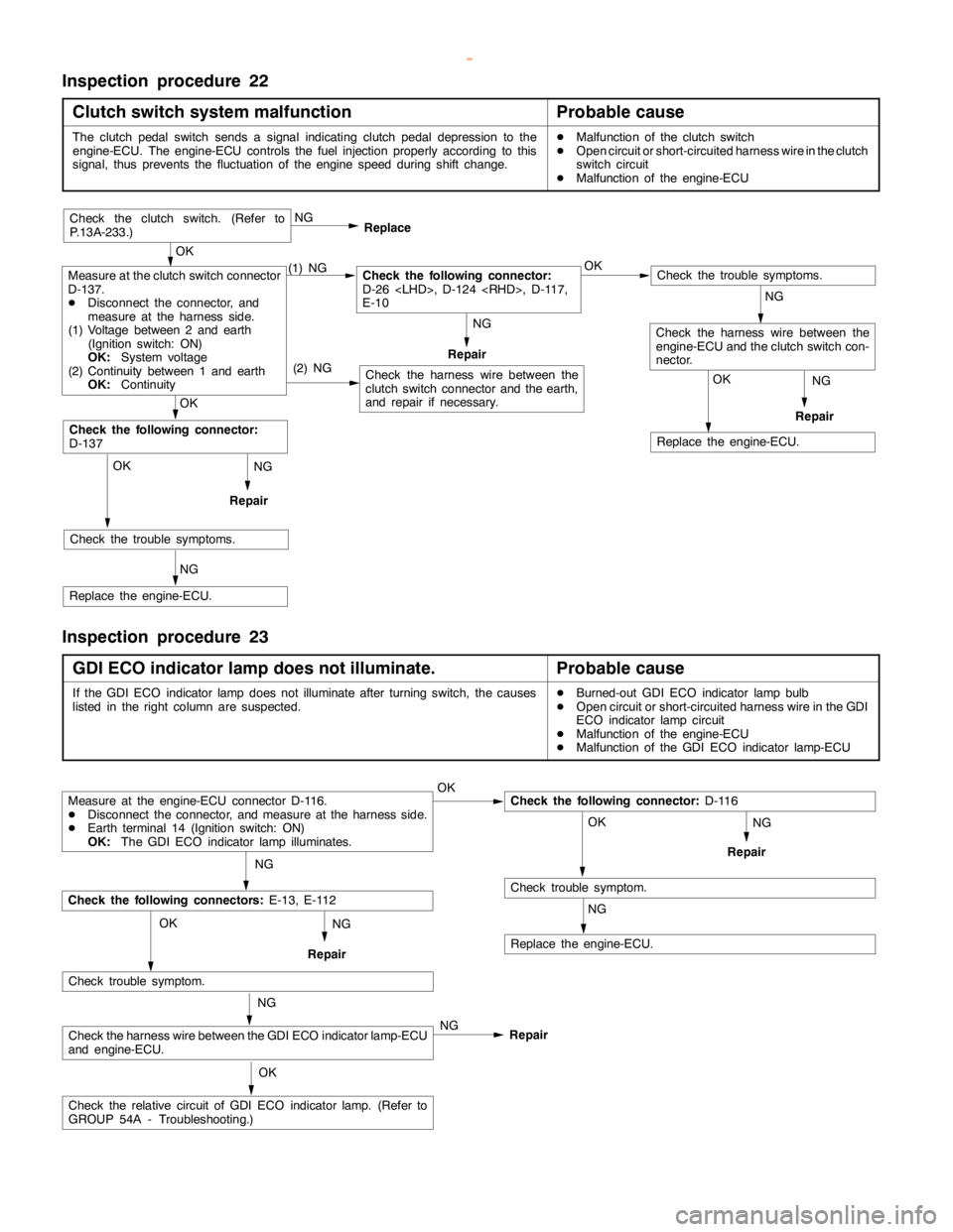
Inspection procedure 22
Clutch switch system malfunction
Probable cause
The clutchpedalswitch sends a signal indicating clutchpedal depression to the
engine-ECU. The engine-ECU controls the fuel injection properly according to this
signal, thus prevents the fluctuation of theenginespeed during shift change.DMalfunction of the clutch switch
DOpen circuit or short-circuited harness wire in the clutch
switch circuit
DMalfunction of the engine-ECU
NG
Repair
NG
Repair
OK
Replace the engine-ECU.
(2) NG
OK
Check the trouble symptoms.
NG
Replace the engine-ECU.
OK
Check the following connector:
D-137
Check the harness wire between the
clutch switch connector and the earth,
and repair if necessary.
Check the trouble symptoms.
Check the harness wire between the
engine-ECU and the clutch switch con-
nector.
Measure at the clutch switch connector
D-137.
DDisconnect the connector, and
measure at the harness side.
(1) Voltage between 2 and earth
(Ignition switch: ON)
OK:
System voltage
(2) Continuity between 1 and earth
OK:
Continuity(1) NGCheck the following connector:
D-26
E-10OK NG
Replace
Repair
OK
Check the clutch switch. (Refer to
P.13A-233.)
NG
NG
Inspection procedure 23
GDI ECO indicator lamp does not illuminate.
Probable cause
If the GDI ECO indicator lampdoes notilluminate after turningswitch, the causes
listed in the right column are suspected.DBurned-out GDI ECO indicator lamp bulb
DOpen circuit or short-circuited harness wire in the GDI
ECO indicator lampcircuit
DMalfunction of the engine-ECU
DMalfunction of the GDI ECO indicator lamp-ECU
NG
Repair
Measure at the engine-ECU connector D-116.
DDisconnect the connector, and measure at the harness side.
DEarth terminal 14 (Ignition switch: ON)
OK:
The GDI ECO indicator lamp illuminates.OKCheck the following connector:
D-116
OK
Check trouble symptom.
NG
Replace the engine-ECU.
NG
Check the following connectors:
E-13, E-112
Check trouble symptom.
Check the harness wire between the GDI ECO indicator lamp-ECU
and engine-ECU.
Check the relative circuit of GDI ECO indicatorlamp.(Refer to
GROUP 54A - Troubleshooting.)NG OK
OK NG
NG
Repair
Repair
www.WorkshopManuals.co.uk
Purchased from www.WorkshopManuals.co.uk
Page 311 of 1839

GDI -Troubleshooting
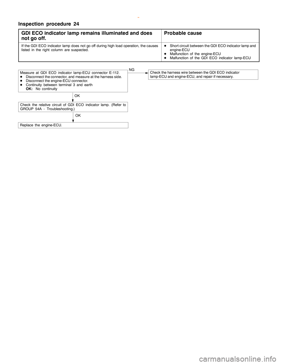
Inspection procedure 24
GDI ECO indicator lamp remains illuminated and does
not go off.
Probable cause
If the GDI ECO indicator lampdoes not go off duringhigh load operation, thecauses
listed in the right column are suspected.DShort circuit between the GDI ECO indicatorlamp and
engine-ECU
DMalfunction of the engine-ECU
DMalfunction of the GDI ECO indicator lamp-ECU
OK
Replace the engine-ECU.
Measure at GDI ECO indicator lamp-ECU connector E-112.
DDisconnect the connector, and measure at the harness side.
DDisconnect the engine-ECU connector.
DContinuity between terminal 3 and earth
OK:
No continuityNGCheck the harness wire between the GDI ECO indicator
lamp-ECU and engine-ECU, and repair if necessary.
OK
Check the relative circuit of GDI ECO indicatorlamp.(Refer to
GROUP 54A - Troubleshooting.)
www.WorkshopManuals.co.uk
Purchased from www.WorkshopManuals.co.uk
Page 380 of 1839

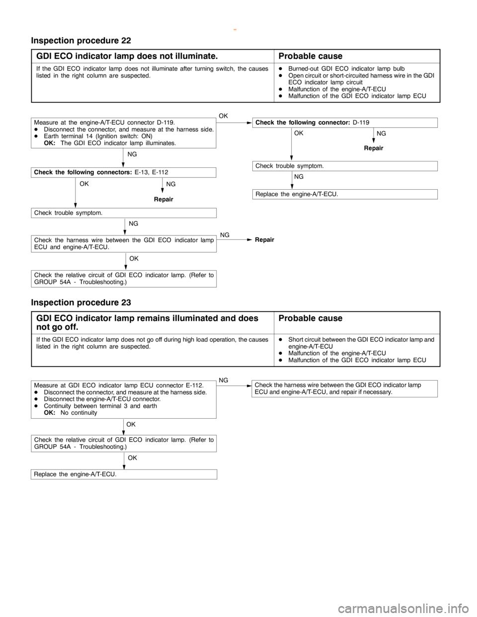
Page 402 of 1839

Page 817 of 1839

ENGINE AND EMISSION CONTROL -Auto-cruise Control SystemENGINE AND EMISSION CONTROL -Auto-cruise Control System17-15
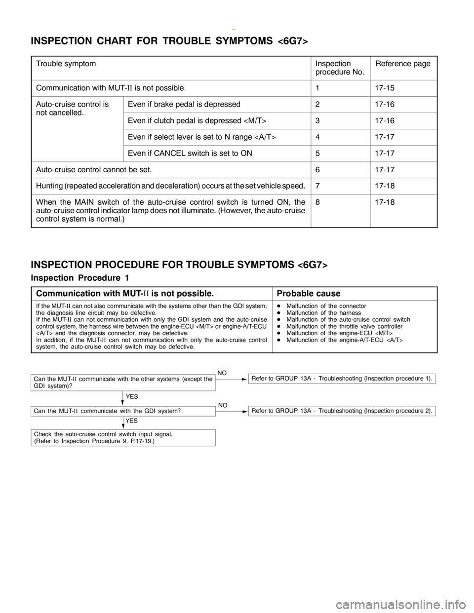
INSPECTION CHART FOR TROUBLE SYMPTOMS <6G7>
Trouble symptomInspection
procedure No.Reference page
Communication with MUT-IIis not possible.117-15
Auto-cruise control isEven if brake pedal is depressed217-16
not cancelled.
Even if clutch pedal is depressed
Even if select lever is set to N range417-17
Even if CANCEL switch is set to ON517-17
Auto-cruise control cannot be set.617-17
Hunting (repeated acceleration and deceleration) occurs at the set vehicle speed.717-18
When the MAIN switch of the auto-cruise control switch is turned ON, the
auto-cruise control indicator lamp does not illuminate. (However, the auto-cruise
control system is normal.)817-18
INSPECTION PROCEDURE FOR TROUBLE SYMPTOMS <6G7>
Inspection Procedure 1
Communication with MUT-II
is not possible.
Probable cause
If the MUT-
IIcan not also communicate with the systems other than the GDI system,
the diagnosis line circuit may be defective.
If the MUT-
IIcan not communication with only the GDI system and the auto-cruise
control system, the harness wire between the engine-ECU
and the diagnosis connector, may be defective.
In addition, if the MUT-
IIcan not communication with only the auto-cruise control
system, the auto-cruise control switch may be defective.DMalfunction of the connector
DMalfunction of the harness
DMalfunction of the auto-cruise control switch
DMalfunction of the throttle valve controller
DMalfunction of the engine-ECU
DMalfunction of the engine-A/T-ECU
NORefer to GROUP 13A - Troubleshooting (Inspection procedure 2).
Can the MUT-
IIcommunicate with the other systems (except the
GDI system)?NORefer to GROUP 13A - Troubleshooting (Inspection procedure 1).
YES
Can the MUT-
IIcommunicate with the GDI system?
YES
Check the auto-cruise control switch input signal.
(Refer to Inspection Procedure 9, P.17-19.)
www.WorkshopManuals.co.uk
Purchased from www.WorkshopManuals.co.uk