2000 MITSUBISHI MONTERO bulb
[x] Cancel search: bulbPage 290 of 1839
GDI -Troubleshooting
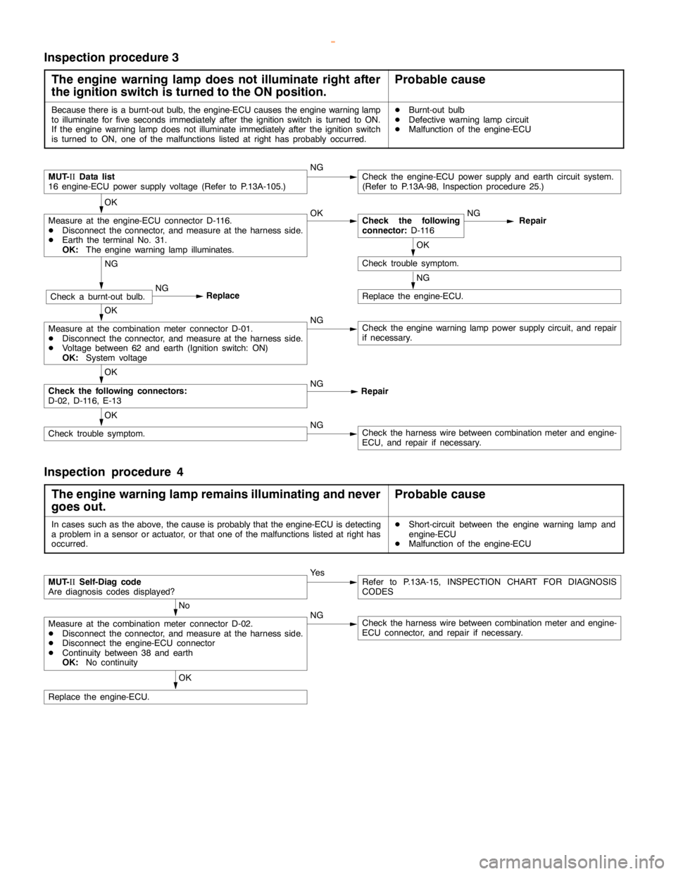
Inspection procedure 3
The engine warning lamp does not illuminate right after
the ignition switch is turned to the ON position.
Probable cause
Because there is a burnt-out bulb, the engine-ECU causes theengine warning lamp
to illuminate forfive seconds immediately after the ignition switch is turned to ON.
If the engine warning lampdoes notilluminate immediately after the ignitionswitch
is turned to ON, one of the malfunctions listed at right has probably occurred.DBurnt-out bulb
DDefective warninglampcircuit
DMalfunction of the engine-ECU
MUT-
IIData list
16 engine-ECU power supply voltage (Refer to P.13A-105.)NGCheck the engine-ECU power supply and earth circuit system.
(Refer to P.13A-98, Inspection procedure 25.)
OK
Measure at the engine-ECU connector D-116.
DDisconnect the connector, and measure at the harness side.
DEarth the terminal No. 31.
OK:
The engine warning lamp illuminates.OKCheck the following
connector:
D-116NG
Repair
OK
Check trouble symptom.
NG
Replace the engine-ECU.
NG
Check a burnt-out bulb.NG
Replace
OK
Measure at the combination meter connector D-01.
DDisconnect the connector, and measure at the harness side.
DVoltage between 62 and earth (Ignition switch: ON)
OK:
System voltageNGCheck theengine warning lamppower supply circuit, and repair
if necessary.
OK
Check the following connectors:
D-02, D-116, E-13NG
Repair
OK
Check trouble symptom.NGCheck the harness wire between combination meter and engine-
ECU, and repair if necessary.
Inspection procedure 4
The engine warning lamp remains illuminating and never
goes out.
Probable cause
In cases such as the above, the cause is probably that the engine-ECU is detecting
a problem in a sensor or actuator, or that one of the malfunctions listed at right has
occurred.DShort-circuit between the engine warning lamp and
engine-ECU
DMalfunction of the engine-ECU
MUT-
IISelf-Diag code
Are diagnosis codes displayed?Ye sRefer to P.13A-15, INSPECTION CHART FOR DIAGNOSIS
CODES
No
Measure at the combination meter connector D-02.
DDisconnect the connector, and measure at the harness side.
DDisconnect the engine-ECU connector
DContinuity between 38 and earth
OK:
No continuityNGCheck the harness wire between combination meter and engine-
ECU connector, and repair if necessary.
OK
Replace the engine-ECU.
www.WorkshopManuals.co.uk
Purchased from www.WorkshopManuals.co.uk
Page 310 of 1839
GDI -Troubleshooting
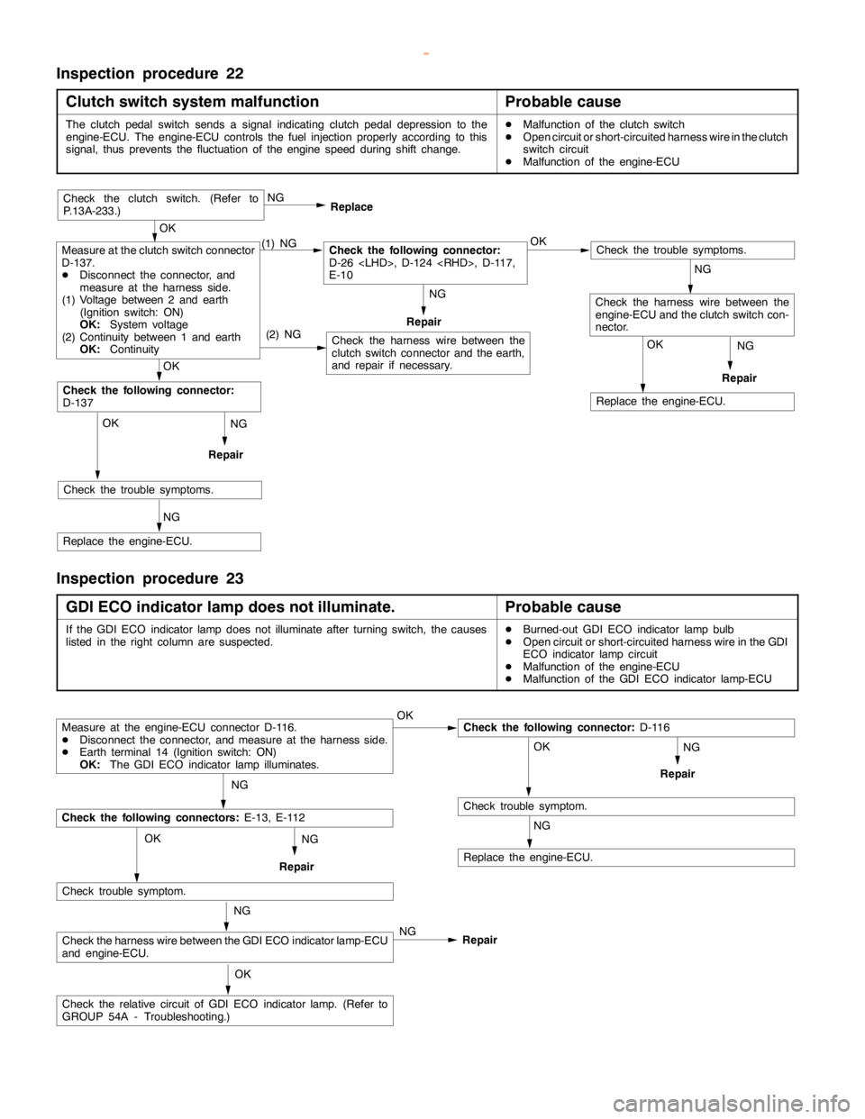
Inspection procedure 22
Clutch switch system malfunction
Probable cause
The clutchpedalswitch sends a signal indicating clutchpedal depression to the
engine-ECU. The engine-ECU controls the fuel injection properly according to this
signal, thus prevents the fluctuation of theenginespeed during shift change.DMalfunction of the clutch switch
DOpen circuit or short-circuited harness wire in the clutch
switch circuit
DMalfunction of the engine-ECU
NG
Repair
NG
Repair
OK
Replace the engine-ECU.
(2) NG
OK
Check the trouble symptoms.
NG
Replace the engine-ECU.
OK
Check the following connector:
D-137
Check the harness wire between the
clutch switch connector and the earth,
and repair if necessary.
Check the trouble symptoms.
Check the harness wire between the
engine-ECU and the clutch switch con-
nector.
Measure at the clutch switch connector
D-137.
DDisconnect the connector, and
measure at the harness side.
(1) Voltage between 2 and earth
(Ignition switch: ON)
OK:
System voltage
(2) Continuity between 1 and earth
OK:
Continuity(1) NGCheck the following connector:
D-26
E-10OK NG
Replace
Repair
OK
Check the clutch switch. (Refer to
P.13A-233.)
NG
NG
Inspection procedure 23
GDI ECO indicator lamp does not illuminate.
Probable cause
If the GDI ECO indicator lampdoes notilluminate after turningswitch, the causes
listed in the right column are suspected.DBurned-out GDI ECO indicator lamp bulb
DOpen circuit or short-circuited harness wire in the GDI
ECO indicator lampcircuit
DMalfunction of the engine-ECU
DMalfunction of the GDI ECO indicator lamp-ECU
NG
Repair
Measure at the engine-ECU connector D-116.
DDisconnect the connector, and measure at the harness side.
DEarth terminal 14 (Ignition switch: ON)
OK:
The GDI ECO indicator lamp illuminates.OKCheck the following connector:
D-116
OK
Check trouble symptom.
NG
Replace the engine-ECU.
NG
Check the following connectors:
E-13, E-112
Check trouble symptom.
Check the harness wire between the GDI ECO indicator lamp-ECU
and engine-ECU.
Check the relative circuit of GDI ECO indicatorlamp.(Refer to
GROUP 54A - Troubleshooting.)NG OK
OK NG
NG
Repair
Repair
www.WorkshopManuals.co.uk
Purchased from www.WorkshopManuals.co.uk
Page 340 of 1839

Page 384 of 1839
Page 402 of 1839
Page 516 of 1839
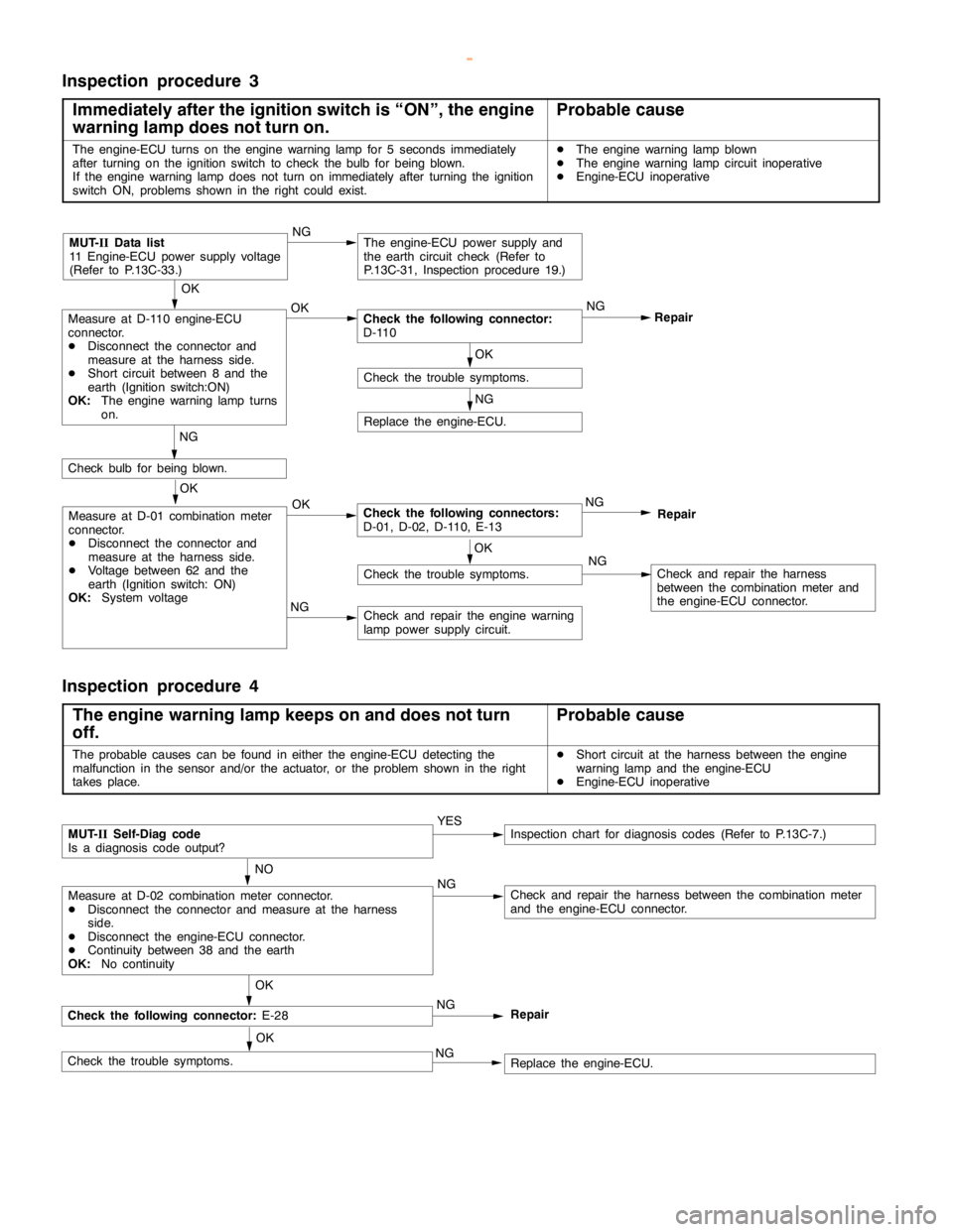
DIESEL FUEL <4M4> -Troubleshooting13C-25
Inspection procedure 3
Immediately after the ignition switch is “ON”, the engine
warning lamp does not turn on.
Probable cause
The engine-ECU turns on theengine warning lamp for 5seconds immediately
after turning on the ignition switch to check thebulb for being blown.
If the engine warning lampdoes not turn on immediately after turning the ignition
switch ON, problems shown in the right could exist.DThe engine warning lamp blown
DThe engine warning lampcircuit inoperative
DEngine-ECU inoperative
NG
Replace the engine-ECU.
NG
Check and repair the harness
between the combination meter and
the engine-ECU connector.
NG
Check and repair theengine warning
lamppower supply circuit.
OK
Check the trouble symptoms.
OK
Measure at D-01 combination meter
connector.
DDisconnect the connector and
measure at the harness side.
DVoltage between 62 and the
earth (Ignition switch: ON)
OK:
System voltageOKCheck the following connectors:
D-01, D-02, D-110, E-13NG
Repair
NG
Checkbulb for being blown.
OK
Check the trouble symptoms.
OK
Measure at D-110 engine-ECU
connector.
DDisconnect the connector and
measure at the harness side.
DShort circuit between 8 and the
earth (Ignition switch:ON)
OK:
The engine warning lampturns
on.OKCheck the following connector:
D-110NG
Repair
MUT-
IIData list
11 Engine-ECU power supply voltage
(Refer to P.13C-33.)NGThe engine-ECU power supply and
the earth circuit check (Refer to
P.13C-31, Inspection procedure 19.)
Inspection procedure 4
The engine warning lamp keeps on and does not turn
off.
Probable cause
The probable causes can be found in either the engine-ECU detecting the
malfunction in the sensor and/or the actuator, or the problem shown in the right
takes place.DShort circuit at the harness between theengine
warning lamp and the engine-ECU
DEngine-ECU inoperative
Check the following connector:
E-28
NO
Measure at D-02 combination meter connector.
DDisconnect the connector and measure at the harness
side.
DDisconnect the engine-ECU connector.
DContinuity between 38 and the earth
OK:
No continuityNGCheck and repair the harness between the combination meter
and the engine-ECU connector.
OK
MUT-
IISelf-Diag code
Is a diagnosis code output?YESInspection chart for diagnosis codes (Refer to P.13C-7.)
Check the trouble symptoms.OKReplace the engine-ECU. NGNG
Repair
www.WorkshopManuals.co.uk
Purchased from www.WorkshopManuals.co.uk
Page 603 of 1839
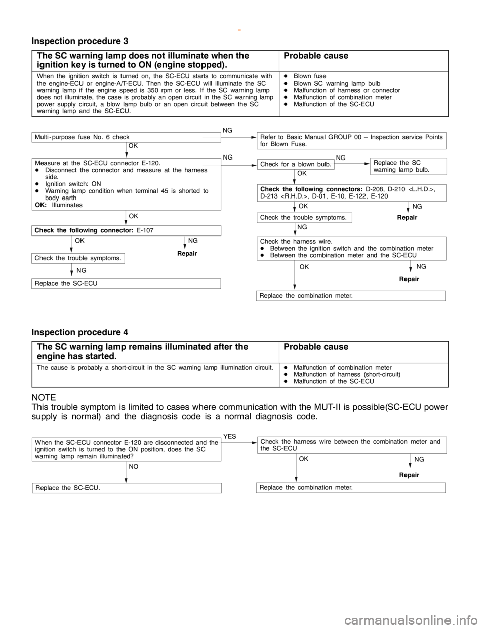
MITSUBISHI SC-Troubleshooting13E-14
Inspection procedure 3
The SC warning lamp does not illuminate when the
ignition key is turned to ON (engine stopped).
Probable cause
When the ignition switch is turned on, the SC-ECU starts to communicate with
the engine-ECU or engine-A/T-ECU. Then the SC-ECU will illuminate the SC
warning lamp if the engine speed is 350 rpm or less. If the SC warning lamp
does not illuminate, the case is probably an open circuit in the SC warning lamp
power supply circuit, a blow lamp bulb or an open circuit between the SC
warning lamp and the SC-ECU.DBlown fuse
DBlown SC warning lamp bulb
DMalfunction of harness or connector
DMalfunction of combination meter
DMalfunction of the SC-ECU
NG
Replace the combination meter.
NG
Repair
OK
NG
Check for a blown bulb.Replace the SC
warning lamp bulb.
OK
NG
Repair
OK
Check the trouble symptoms.
Multi - purpose fuse No. 6 checkNGRefer to Basic Manual GROUP 00 – Inspection service Points
for Blown Fuse.
NG
Check the harness wire.
DBetween the ignition switch and the combination meter
DBetween the combination meter and the SC-ECU
OK
OK
Replace the SC-ECU
Check the following connector:
E-107
NG
RepairCheck the trouble symptoms.OK
NG
Check the following connectors:
D-208, D-210
D-213
Measure at the SC-ECU connector E-120.
DDisconnect the connector and measure at the harness
side.
DIgnition switch: ON
DWarning lamp condition when terminal 45 is shorted to
body earth
OK:
Illuminates
Inspection procedure 4
The SC warning lamp remains illuminated after the
engine has started.
Probable cause
The cause is probably a short-circuit in the SC warning lamp illumination circuit.DMalfunction of combination meter
DMalfunction of harness (short-circuit)
DMalfunction of the SC-ECU
NOTE
This trouble symptom is limited to cases where communication with the MUT-II is possible(SC-ECU power
supply is normal) and the diagnosis code is a normal diagnosis code.
When the SC-ECU connector E-120 are disconnected and the
ignition switch is turned to the ON position, does the SC
warning lamp remain illuminated?YES
NO
Replace the SC-ECU.Replace the combination meter.
NG
Repair
OK
Check the harness wire between the combination meter and
the SC-ECU
www.WorkshopManuals.co.uk
Purchased from www.WorkshopManuals.co.uk
Page 640 of 1839
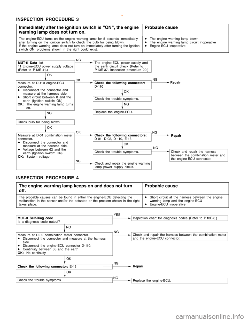
DIESEL FUEL <4D5-stepIII>-Troubleshooting13E-30
INSPECTION PROCEDURE 3
Immediately after the ignition switch is “ON”, the engine
warning lamp does not turn on.
Probable cause
The engine-ECU turns on the engine warning lamp for 5 seconds immediately
after turning on the ignition switch to check the bulb for being blown.
If the engine warning lamp does not turn on immediately after turning the ignition
switch ON, problems shown in the right could exist.DThe engine warning lamp blown
DThe engine warning lamp circuit inoperative
DEngine-ECU inoperative
NG
Replace the engine-ECU.
NG
Check and repair the harness
between the combination meter and
the engine-ECU connector.
NG
Check and repair the engine warning
lamp power supply circuit.
OK
Check the trouble symptoms.
OK
Measure at D-01 combination meter
connector.
DDisconnect the connector and
measure at the harness side.
DVoltage between 62 and the
earth (Ignition switch: ON)
OK:System voltageOKCheck the following connectors:
D-01, D-02, D-110, E-13NG
Repair
NG
Check bulb for being blown.
OK
Check the trouble symptoms.
OK
Measure at D-110 engine-ECU
connector.
DDisconnect the connector and
measure at the harness side.
DShort circuit between 8 and the
earth (Ignition switch: ON)
OK:The engine warning lamp turns
on.OKCheck the following connector:
D-110NG
Repair
MUT-IIData list
11 Engine-ECU power supply voltage
(Refer to P.13E-41.)NGThe engine-ECU power supply and
the earth circuit check (Refer to
P.13E-37, Inspection procedure 20.)
INSPECTION PROCEDURE 4
The engine warning lamp keeps on and does not turn
off.
Probable cause
The probable causes can be found in either the engine-ECU detecting the
malfunction in the sensor and/or the actuator, or the problem shown in the right
takes place.DShort circuit at the harness between the engine
warning lamp and the engine-ECU
DEngine-ECU inoperative
Check the following connector:E-13
NO
Measure at D-02 combination meter connector.
DDisconnect the connector and measure at the harness
side.
DDisconnect the engine-ECU connector D-110.
DContinuity between 38 and the earth
OK:No continuityNGCheck and repair the harness between the combination meter
and the engine-ECU connector.
OK
MUT-IISelf-Diag code
Is a diagnosis code output?YESInspection chart for diagnosis codes (Refer to P.13E-8.)
Check the trouble symptoms.OKReplace the engine-ECU. NGNG
Repair
www.WorkshopManuals.co.uk
Purchased from www.WorkshopManuals.co.uk