2000 MITSUBISHI MONTERO bulb
[x] Cancel search: bulbPage 820 of 1839
ENGINE AND EMISSION CONTROL -Auto-cruise Control System17-18
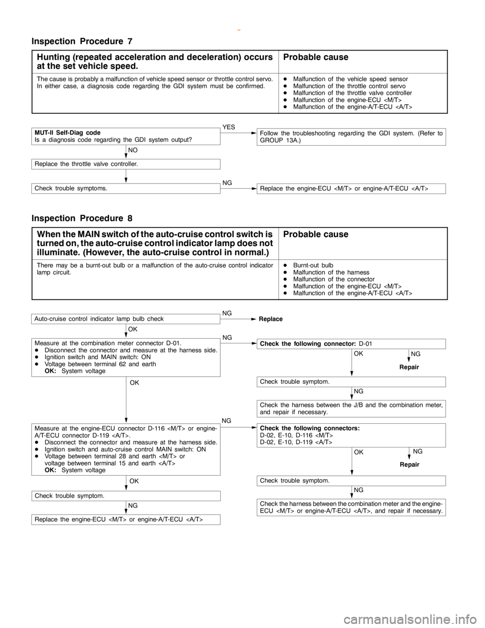
Inspection Procedure 7
Hunting (repeated acceleration and deceleration) occurs
at the set vehicle speed.
Probable cause
The cause is probably a malfunction of vehicle speed sensor or throttle control servo.
In either case, a diagnosis code regarding the GDI system must be confirmed.DMalfunction of the vehicle speed sensor
DMalfunction of the throttle control servo
DMalfunction of the throttle valve controller
DMalfunction of the engine-ECU
DMalfunction of the engine-A/T-ECU
MUT-II Self-Diag code
Is a diagnosis code regarding the GDI system output?YES
NO
Replace the throttle valve controller.
Check trouble symptoms.NGReplace the engine-ECU
Follow the troubleshooting regarding the GDI system. (Refer to
GROUP 13A.)
Inspection Procedure 8
When the MAIN switch of the auto-cruise control switch is
turned on, the auto-cruise control indicator lamp does not
illuminate. (However, the auto-cruise control in normal.)
Probable cause
There may be a burnt-out bulb or a malfunction of the auto-cruise control indicator
lampcircuit.DBurnt-out bulb
DMalfunction of the harness
DMalfunction of the connector
DMalfunction of the engine-ECU
DMalfunction of the engine-A/T-ECU
OK
Auto-cruise control indicatorlamp bulbcheckNG
Replace
NG
Repair
OK
NG
OK
Check trouble symptom.
NG
Check the harness between the J/B and the combination meter,
and repair if necessary.
Check the following connectors:
D-02, E-10, D-116
D-02, E-10, D-119
OK
Check trouble symptom.
NG
Repair
NG
Replace the engine-ECU
Measure at the engine-ECU connector D-116
A/T-ECU connector D-119 .
DDisconnect the connector and measure at the harness side.
DIgnition switch and auto-cruise control MAIN switch: ON
DVoltage between terminal 28 and earth
voltage between terminal 15 and earth
OK:System voltage
Measure at the combination meter connector D-01.
DDisconnect the connector and measure at the harness side.
DIgnition switch and MAIN switch: ON
DVoltage between terminal 62 and earth
OK:System voltageCheck the following connector:D-01
NG
Check the harness between the combination meter and the engine-
ECU
Check trouble symptom.
www.WorkshopManuals.co.uk
Purchased from www.WorkshopManuals.co.uk
Page 825 of 1839
ENGINE AND EMISSION CONTROL -Auto-cruise Control System17-23
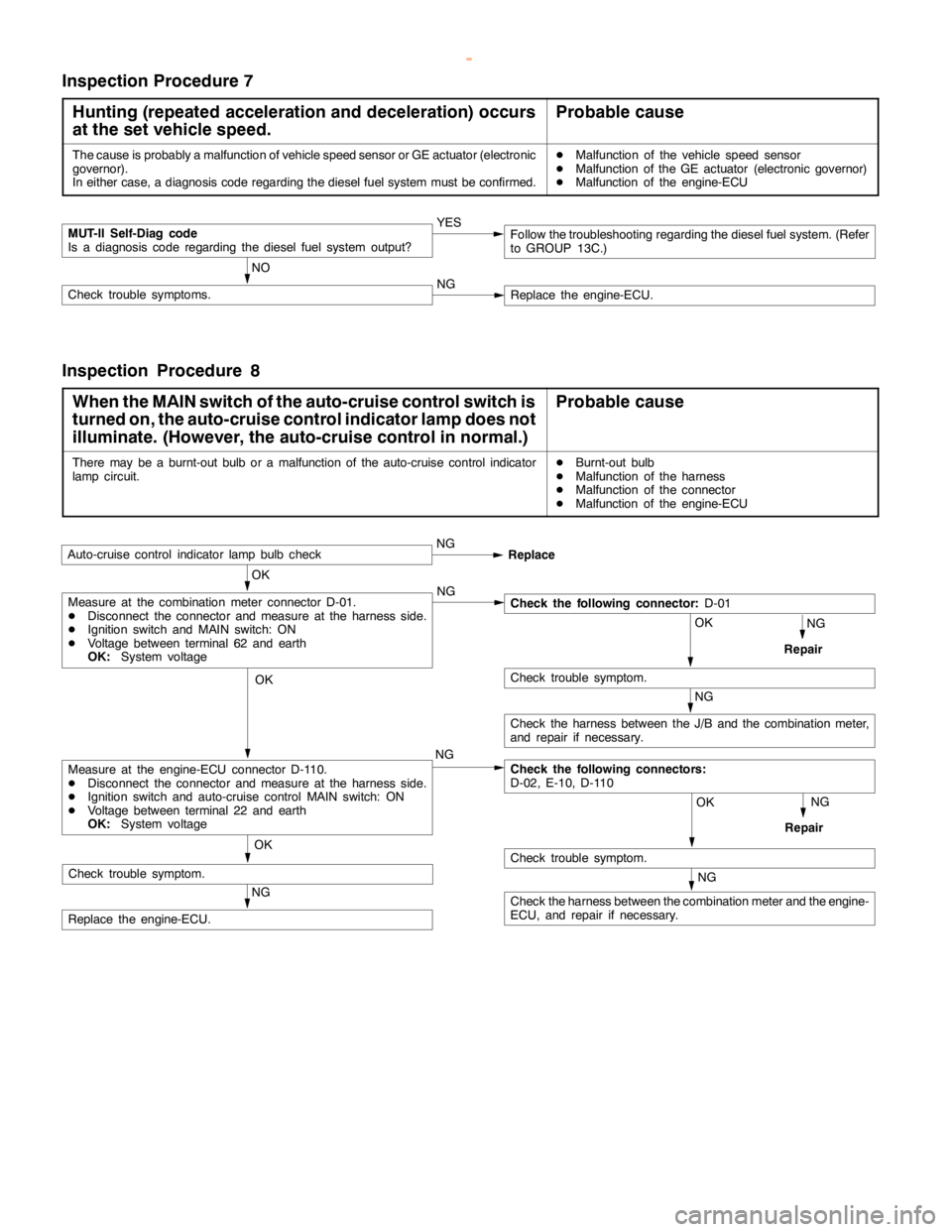
Inspection Procedure 7
Hunting (repeated acceleration and deceleration) occurs
at the set vehicle speed.
Probable cause
The cause is probably a malfunction of vehicle speed sensor or GE actuator (electronic
governor).
In either case, a diagnosis code regarding the diesel fuel system must be confirmed.DMalfunction of the vehicle speed sensor
DMalfunction of the GE actuator (electronic governor)
DMalfunction of the engine-ECU
MUT-II Self-Diag code
Is a diagnosis code regarding the diesel fuel system output?YES
NO
Check trouble symptoms.NGReplace the engine-ECU.
Follow the troubleshooting regarding the diesel fuel system. (Refer
to GROUP 13C.)
Inspection Procedure 8
When the MAIN switch of the auto-cruise control switch is
turned on, the auto-cruise control indicator lamp does not
illuminate. (However, the auto-cruise control in normal.)
Probable cause
There may be a burnt-out bulb or a malfunction of the auto-cruise control indicator
lampcircuit.DBurnt-out bulb
DMalfunction of the harness
DMalfunction of the connector
DMalfunction of the engine-ECU
OK
Auto-cruise control indicatorlamp bulbcheckNG
Replace
NG
Repair
OK
NG
OK
Check trouble symptom.
NG
Check the harness between the J/B and the combination meter,
and repair if necessary.
Check the following connectors:
D-02, E-10, D-110
OK
Check trouble symptom.
NG
Repair
NG
Replace the engine-ECU.NG
Measure at the engine-ECU connector D-110.
DDisconnect the connector and measure at the harness side.
DIgnition switch and auto-cruise control MAIN switch: ON
DVoltage between terminal 22 and earth
OK:System voltage
Measure at the combination meter connector D-01.
DDisconnect the connector and measure at the harness side.
DIgnition switch and MAIN switch: ON
DVoltage between terminal 62 and earth
OK:System voltageCheck the following connector:D-01
NG
Check the harness between the combination meter and the engine-
ECU, and repair if necessary. OK
Check trouble symptom.
www.WorkshopManuals.co.uk
Purchased from www.WorkshopManuals.co.uk
Page 1008 of 1839

AUTOMATIC TRANSMISSION -On-vehicle ServiceAUTOMATIC TRANSMISSION -On-vehicle Service23-107
HYDRAULIC PRESSURE TEST DIAGNOSIS TABLE
SymptomProblem location
All hydraulic pressures are too highMalfunction of regulator valve
All hydraulic pressures are too lowMalfunction of oil pump
Blocked oil filter
Blocked oil cooler
Malfunction of regulator valve
Malfunction of relief valve
Incorrect valve body installation
Abnormal hydraulic pressure in R range
onlyMalfunction of regulator valve
Abnormal hydraulic pressure in 3rd or 4th
onlyMalfunction of regulator valve
Malfunction of switch bulb
Abnormal UD pressure onlyMalfunction of oil seal K, L, M or Q
Malfunction of underdrive solenoid valve
Malfunction of underdrive pressure control valve
Abnormality with check ball
Blocked orifices
Incorrect valve body installation
Abnormal REV pressure onlyMalfunction of oil seal A, B or C
Abnormality with check ball
Blocked orifices
Incorrect valve body installation
Abnormal OD pressure onlyMalfunction of oil seal D, E or F
Malfunction of overdrive solenoid valve
Malfunction of overdrive pressure control valve
Abnormality with check ball
Blocked orifices
Incorrect valve body installation
Abnormal DIR pressure onlyMalfunction of oil seal R, S or T
Malfunction of low & reverse solenoid valve (also used for the direct
clutch)
Malfunction of low & reverse pressure control valve
Malfunction of switch bulb
Malfunction of fail-safe valve C
Blocked orifices
Incorrect valve body installation
Abnormal LR pressure onlyMalfunction of oil seal I, J or P
Malfunction of low & reverse solenoid valve (also used for the direct
clutch)
Malfunction of low & reverse pressure control valve
Malfunction of switch bulb
Malfunction of fail-safe valve A
Abnormality with check ball
Blocked orifices
Incorrect valve body installation
Abnormal 2ND pressure onlyMalfunction of oil seal G, H or O
Malfunction of second solenoid valve
Malfunction of second pressure control valve
Malfunction of fail-safe valve B
Blocked orifices
Incorrect valve body installation
www.WorkshopManuals.co.uk
Purchased from www.WorkshopManuals.co.uk
Page 1222 of 1839
BASIC BRAKE SYSTEM -Troubleshooting35A-14
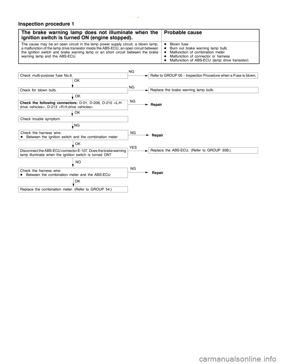
Inspection procedure 1
The brake warning lamp does not illuminate when the
ignition switch is turned ON (engine stopped).
Probable cause
The cause may be anopencircuit in thelamppower supply circuit, a blown lamp,
a malfunction of the lampdrive transistor inside the ABS-ECU, anopencircuit between
the ignition switch and brake warninglamp or anshort circuit between the brake
warning lamp and theABS-ECU.DBlown fuse
DBurn out brake warninglamp bulb
DMalfunction of combination meter
DMalfunction of connector or harness
DMalfunction of ABS-ECU (lamp drive transistor)
Repair NG NG
NO
Replace the ABS-ECU. (Refer to GROUP 35B.)
Repair
Repair
NG
OK
Check for blown bulb.Replace the brake warninglamp bulb.
OK
Check the following connectors:
D-01, D-208, D-210
NG
Replace the combination meter. (Refer to GROUP 54.)
OK
Check trouble symptom.
OK
YES
Check multi-purpose fuse No.6.NGRefer to GROUP 00 – Inspection Procedure when a Fuse is blown.
Check the harness wire:
DBetween the ignition switch and the combination meter
Check the harness wire:
DBetween the combination meter and the ABS-ECU
Disconnect the ABS-ECU connector E-107. Does the brake warning
lamp illuminatewhen the ignition switch is turned ON?
NG
OK
www.WorkshopManuals.co.uk
Purchased from www.WorkshopManuals.co.uk
Page 1283 of 1839
ABS <4WD> -Troubleshooting35B-20
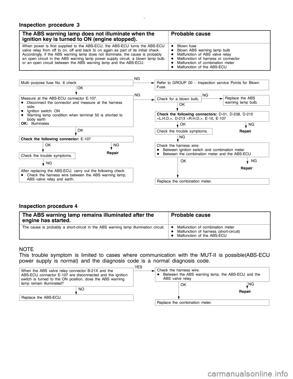
Inspection procedure 3
The ABS warning lamp does not illuminate when the
ignition key is turned to ON (engine stopped).
Probable cause
When power is first supplied to the ABS-ECU, the ABS-ECU turns the ABS-ECU
valve relay from off to on, off and back to onagain aspart of its initial check.
Accordingly, if the ABS warninglampdoes not illuminate, the cause is probably
an opencircuit in the ABS warninglamppower supply circuit, a blownlamp bulb
or an opencircuit between the ABS warninglamp and theABS-ECU.DBlown fuse
DBlown ABS warninglamp bulb
DMalfunction of ABS valve relay
DMalfunction of harness or connector
DMalfunction of combination meter
DMalfunction of the ABS-ECU
NG
Replace the combination meter.
NG
Repair
OK
NG
Check for a blown bulb.Replace the ABS
warning lamp bulb.
OK
NG
Repair
OK
Check the trouble symptoms.
Multi - purpose fuse No. 6 checkNGRefer to GROUP 00 – Inspection service Points for Blown
Fuse.
NG
Check the harness wire.
DBetween ignition switch and combination meter
DBetween the combination meter and the ABS-ECU
OK
OK
After replacing the ABS-ECU, carry out the following check.
DCheck the harness wire between the ABS warning lamp,
ABS valve relay and earth.
Check the following connector:E-107
NG
RepairCheck the trouble symptoms.OK
NG
Check the following connectors:D-01, D-208, D-210
Measure at the ABS-ECU connector E-107.
DDisconnect the connector and measure at the harness
side.
DIgnition switch: ON
DWarning lamp conditionwhen terminal 50 is shorted to
body earth
OK:Illuminates
Inspection procedure 4
The ABS warning lamp remains illuminated after the
engine has started.
Probable cause
The cause is probably a short-circuit in the ABS warninglamp illuminationcircuit.DMalfunction of combination meter
DMalfunction of harness (short-circuit)
DMalfunction of the ABS-ECU
NOTE
This trouble symptom is limited to cases where communication with the MUT-II is possible(ABS-ECU
power supply is normal) and the diagnosis code is a normal diagnosis code.
When the ABS valve relay connector B-21X and the
ABS-ECU connector E-107 are disconnected and the ignition
switch is turned to the ON position, does the ABS warning
lamp remain illuminated?YES
NO
Replace the ABS-ECU.
Replace the combination meter.
NG
Repair
OK
Check the harness wire.
DBetween the ABS warning lamp, the ABS-ECU and the
ABS valve relay
www.WorkshopManuals.co.uk
Purchased from www.WorkshopManuals.co.uk
Page 1514 of 1839
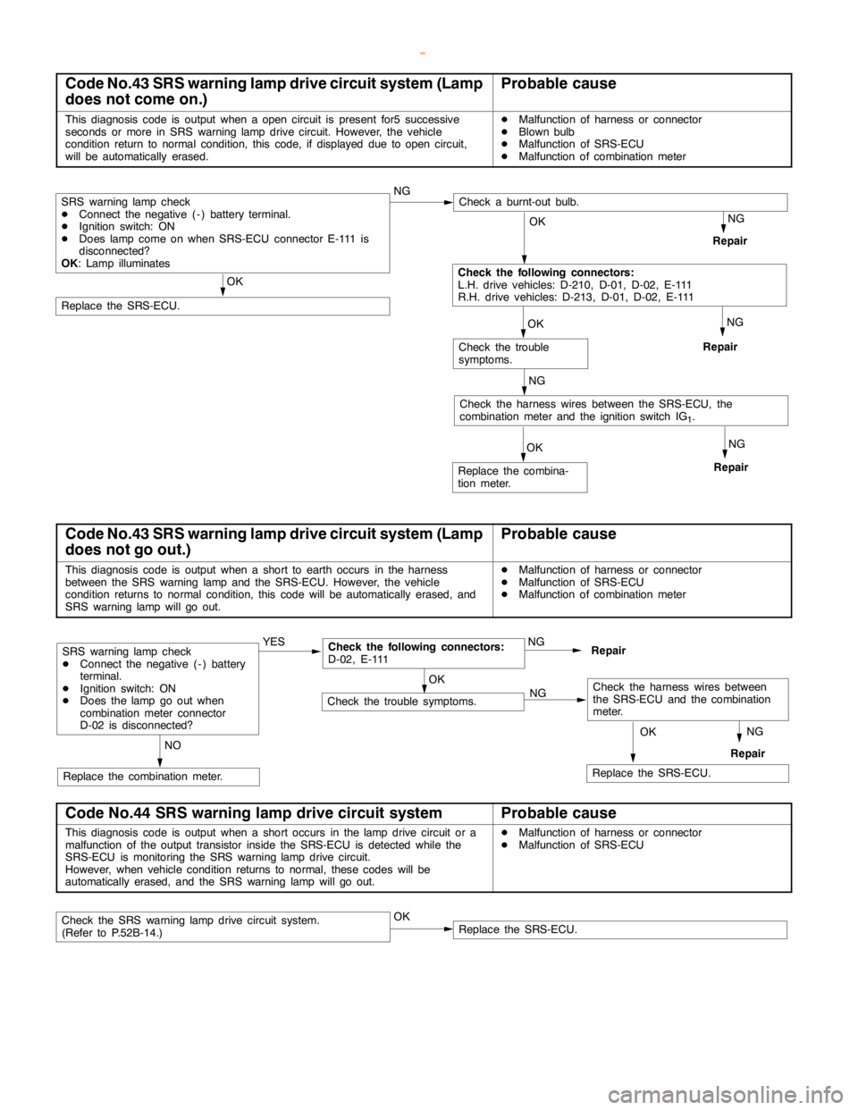
SRS -Troubleshooting52B-14
Code No.43 SRS warning lamp drive circuit system (Lamp
does not come on.)Probable cause
This diagnosis code is output when aopencircuit is present for5 successive
seconds or more in SRS warninglampdrive circuit. However, the vehicle
condition return to normal condition, this code, if displayed due toopencircuit,
will be automatically erased.DMalfunction of harness or connector
DBlownbulb
DMalfunction of SRS-ECU
DMalfunction of combination meter
NGOK
NG
NGOK
Check the trouble
symptoms.
NG
Repair
Check the harness wires between the SRS-ECU, the
combination meter and the ignition switch IG
1.
OK
Replace the SRS-ECU.
Repair
Repair
OK
Check the following connectors:
L.H. drive vehicles: D-210, D-01, D-02, E-111
R.H. drive vehicles: D-213, D-01, D-02, E-111
SRS warning lampcheck
DConnect the negative ( - ) battery terminal.
DIgnition switch: ON
DDoeslampcome on when SRS-ECU connector E-111 is
disconnected?
OK: Lamp illuminatesNGCheck a burnt-out bulb.
Replace the combina-
tion meter.
Code No.43 SRS warning lamp drive circuit system (Lamp
does not go out.)Probable cause
This diagnosis code is output when a short to earth occurs in the harness
between the SRS warning lamp and theSRS-ECU. However, the vehicle
condition returns to normal condition, this code will be automatically erased, and
SRS warning lampwill go out.DMalfunction of harness or connector
DMalfunction of SRS-ECU
DMalfunction of combination meter
OKNG
NG
RepairNG
NO
Replace the combination meter.
SRS warning lampcheck
DConnect the negative ( - ) battery
terminal.
DIgnition switch: ON
DDoes thelamp go outwhen
combination meter connector
D-02 is disconnected?YESCheck the following connectors:
D-02, E-111Repair
Check the trouble symptoms.
OK
Replace the SRS-ECU.
Check the harness wires between
the SRS-ECU and the combination
meter.
Code No.44 SRS warning lamp drive circuit systemProbable cause
This diagnosis code is output when a short occurs in thelampdrive circuit or a
malfunction of the output transistor inside the SRS-ECU is detected while the
SRS-ECU is monitoring the SRS warninglampdrive circuit.
However, when vehicle condition returns to normal, these codes will be
automatically erased, and the SRS warning lampwill go out.DMalfunction of harness or connector
DMalfunction of SRS-ECU
Check the SRS warninglampdrive circuit system.
(Refer to P.52B-14.)OKReplace the SRS-ECU.
www.WorkshopManuals.co.uk
Purchased from www.WorkshopManuals.co.uk
Page 1572 of 1839

54A-2
CHASSIS
ELECTRICAL
CONTENTS
BATTERY 4
..............................
SERVICE SPECIFICATIONS 4..................
ON-VEHICLE SERVICE 4......................
Electrolyte Level and Specific Gravity Check 4..
Charging 5.................................
Battery Test 5...............................
IGNITION SWITCH AND IMMOBILIZER
SPECIAL TOOLS 6............................
TROUBLESHOOTING 6........................
IGNITION SWITCH AND
IMMOBILIZER-ECU 11.........................
IGNITION SWITCH AND IMMOBILIZER
<4D56> 14...............................
SPECIAL TOOLS 14...........................
TROUBLESHOOTING 14.......................
IGNITION SWITCH AND IMMOBILIZER-ECU
19 ............................................
COMBINATION METER 23................
SERVICE SPECIFICATIONS 23.................
SEALANTS 24................................
SPECIAL TOOLS 24...........................
TROUBLESHOOTING 24.......................
ON-VEHICLE SERVICE 30.....................
Speedometer Check 30......................
Tachometer Check 30........................
Fuel Gauge Unit Check 31....................Engine Coolant Temperature Gauge Unit Check
32 .........................................
COMBINATION METER 33.....................
HEADLAMP ASSEMBLY 36...............
SERVICE SPECIFICATIONS 36.................
SPECIAL TOOLS 36...........................
TROUBLESHOOTING 36.......................
ON-VEHICLE SERVICE 36.....................
Headlamp Aiming Adjustment 36..............
Luminance Measurement 38..................
Headlamp Bulb Replacement 39...............
HEADLAMP ASSEMBLY 40....................
FOG LAMPS 41..........................
SERVICE SPECIFICATIONS 41.................
SPECIAL TOOLS 41...........................
TROUBLESHOOTING 41.......................
ON-VEHICLE SERVICE 41.....................
Fog Lamp Aiming Check 41...................
FOG LAMPS 44...............................
SIDE TURN-SIGNAL LAMPS 45...........
SPECIAL TOOLS 45...........................
SIDE TURN-SIGNAL LAMPS 46................
ROOM LAMP 46.........................
TROUBLESHOOTING 46.......................
CONTINUED ON NEXT PAGE
www.WorkshopManuals.co.uk
Purchased from www.WorkshopManuals.co.uk
Page 1691 of 1839

SWS -General InformationSWS -General Information54B-5
HEADLAMP WASHER
If the headlamp washer switch at the steering
column is placed in the ON position when the ignition
switch is in the ACC or ON position and theheadlamp switch is in the ON position, the headlamp
washer drive signal is turned ON for 0.5 second.
IGNITION KEY HOLE ILLUMINATION LAMP
When the ignition switch is turned to LOCK (OFF) or
ACC position with the driver’s door opened, the
ignition key hole illumination lamp is illuminated.
If the door is closed in that state, the lamp goes out
after 30 seconds. Vehicles with keyless entrysystem, it illuminates for 30 seconds after the
ignition key is removed. In either case the lamp goes
out when the ignition switch is turned to ON position.
HEADLAMP
Headlamp Automatic Shutdown Function
If the ignition switch is turned to LOCK (OFF) or
ACC position, when the headlamps are on, the
headlamps will be switched off in three minutes.
If the driver’s door is opened within that three-minute
period, the headlamps will be switched off
automatically. This prevents the battery from
discharged.
In addition, if the headlamps are turned on when
the ignition switch is at LOCK (OFF) or ACC position,
the headlamps will not be switched off.Headlamp Dimmer Switch Automatic Reset
Function
This function allows the dimmer switch to be reset
to the low-beam position whenever the headlamp
switch is turned ON.
Daytime Running Lamp (DRL) Function
If the ignition switch is turned to ON when the
headlamps and tail lamps are off, the headlamps
(low-beam) and tail lamps turn on.
FLASHER TIMER
Turn-signal Lamp
When the ignition switch is turned to ON position
and turn-signal lamp switch is placed in the ON
position for right or left turn signaling, the system
generates turn-signal lamp drive signals (flashing
signals).
The system also notifies of a blown turn-signal lamp
bulb by shortening the flashing intervals of the
corresponding indicator lamp.Hazard Warning Lamp
The system detects a change from ON to OFF
of the hazard lamp input signal and activates the
hazard lamps if they are not in operation or
deactivates the lamps if they are operating (reversal
of state between activation and deactivation).
FRONT FOG LAMP
If the front fog lamp switch is turned ON at the
condition that the headlamp or the tail lamp is turned
ON (including the illumination by the automatic
lighting function), the front fog lamp is turned ON.Whenever the tail lamps are turned on at the next
time, the front fog lamps will always be off regardless
of the switch positions. In addition, if the tail lamp
is switched off by the automatic lighting system,
the front fog lamp will also be switched off. However,
the front fog lamp will be illuminated when the tail
lamp is switched on.
www.WorkshopManuals.co.uk
Purchased from www.WorkshopManuals.co.uk