2000 MITSUBISHI MONTERO radio
[x] Cancel search: radioPage 285 of 1839
GDI -Troubleshooting
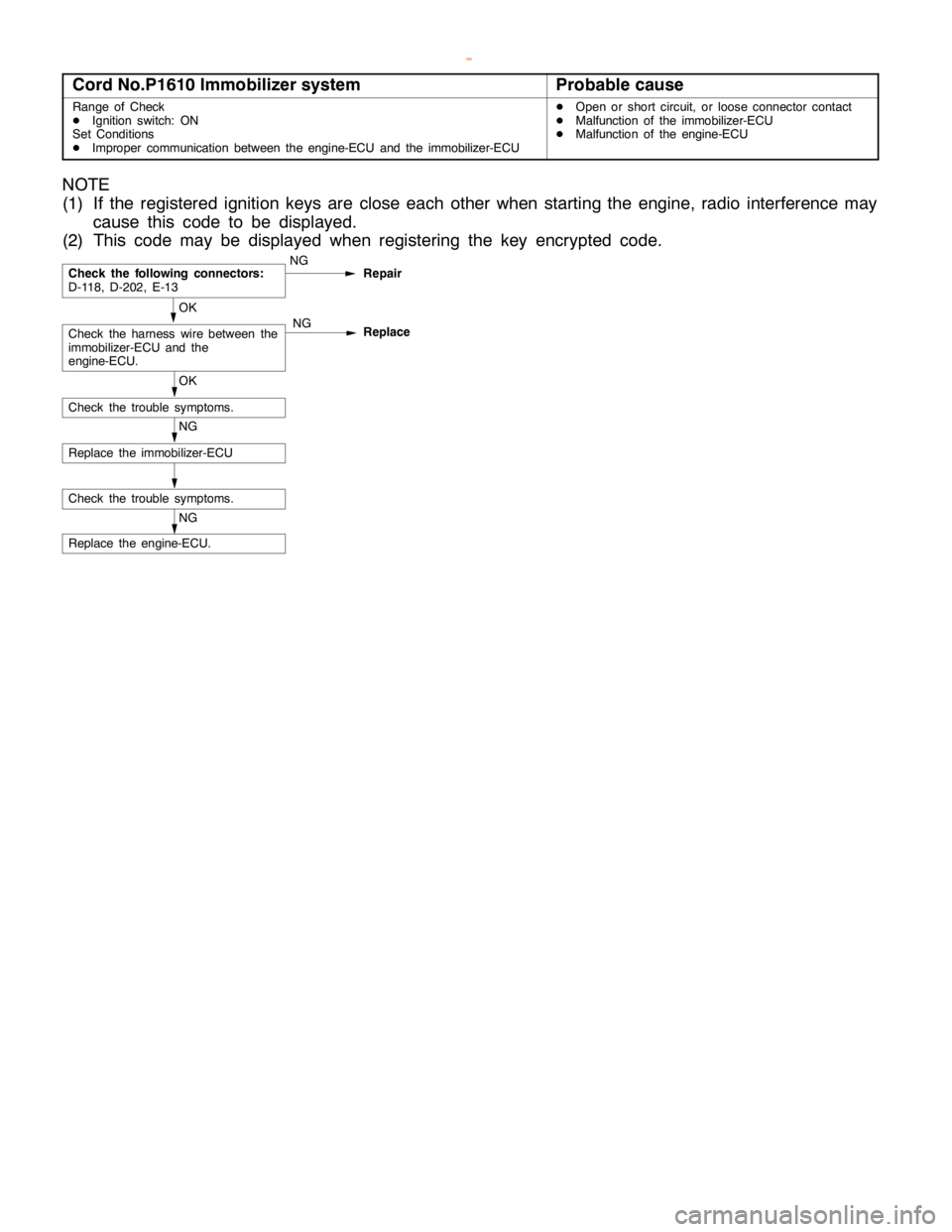
Cord No.P1610 Immobilizer systemProbable cause
Range of Check
DIgnition switch: ON
Set Conditions
DImproper communication between the engine-ECU and the immobilizer-ECUDOpen or short circuit, or loose connector contact
DMalfunction of the immobilizer-ECU
DMalfunction of the engine-ECU
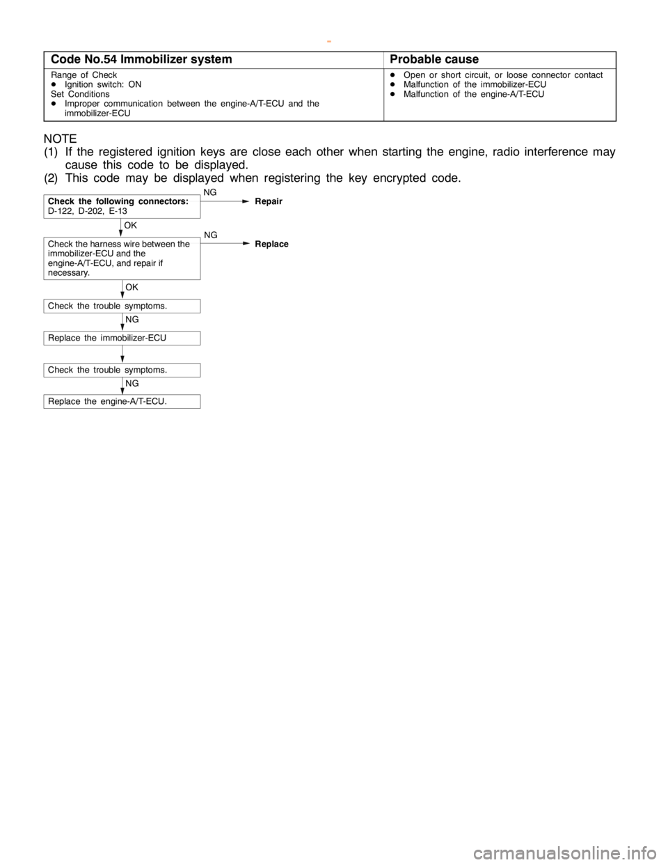
NOTE
(1) If the registered ignition keys are close each other when starting the engine, radio interference may
cause this code to be displayed.
(2) This code may be displayed when registering the key encrypted code.
NG
Replace the engine-ECU.
Check the trouble symptoms.
NG
Replace the immobilizer-ECU
OK
Check the trouble symptoms.
OK
Check the harness wire between the
immobilizer-ECU and the
engine-ECU.NG
Replace
Check the following connectors:
D-118, D-202, E-13NG
Repair
www.WorkshopManuals.co.uk
Purchased from www.WorkshopManuals.co.uk
Page 364 of 1839
Page 513 of 1839
DIESEL FUEL <4M4> -TroubleshootingDIESEL FUEL <4M4> -Troubleshooting13C-22
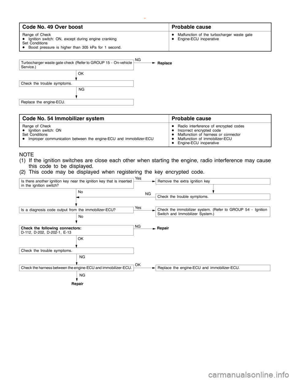
Code No. 49 Over boostProbable cause
Range of Check
DIgnition switch: ON, except duringenginecranking
Set Conditions
DBoost pressure is higher than 305 kPa for 1 second.DMalfunction of the turbocharger waste gate
DEngine-ECU inoperative
Turbocharger waste gate check (Refer to GROUP 15 - On-vehicle
Service.)NG
OK
Check the trouble symptoms.
NG
Replace the engine-ECU.Replace
Code No. 54 Immobilizer systemProbable cause
Range of Check
DIgnition switch: ON
Set Conditions
DImproper communication between the engine-ECU and immobilizer-ECUDRadio interference of encrypted codes
DIncorrect encrypted code
DMalfunction of harness or connector
DMalfunction of immobilizer-ECU
DEngine-ECU inoperative
NOTE
(1) If the ignition switches are close each other when starting the engine, radio interference may cause
this code to be displayed.
(2) This code may be displayed when registering the key encrypted code.
Is there another ignition key near the ignition key that is inserted
in the ignition switch?Ye sRemove the extra ignition key
No
Check the following connectors:
D-112, D-202, D-202-1, E-13NG
Repair
No
Is a diagnosis code output from the immobilizer-ECU?Ye sCheck the immobilizer system. (Refer to GROUP 54 - Ignition
Switch and Immobilizer System.)
NG OK
Check the trouble symptoms.
Check the harness between the engine-ECU and immobilizer-ECU.OKReplace the engine-ECU and immobilizer-ECU.
Check the trouble symptoms. NG
RepairNG
www.WorkshopManuals.co.uk
Purchased from www.WorkshopManuals.co.uk
Page 637 of 1839
DIESEL FUEL <4D5-stepIII>-Troubleshooting13E-27
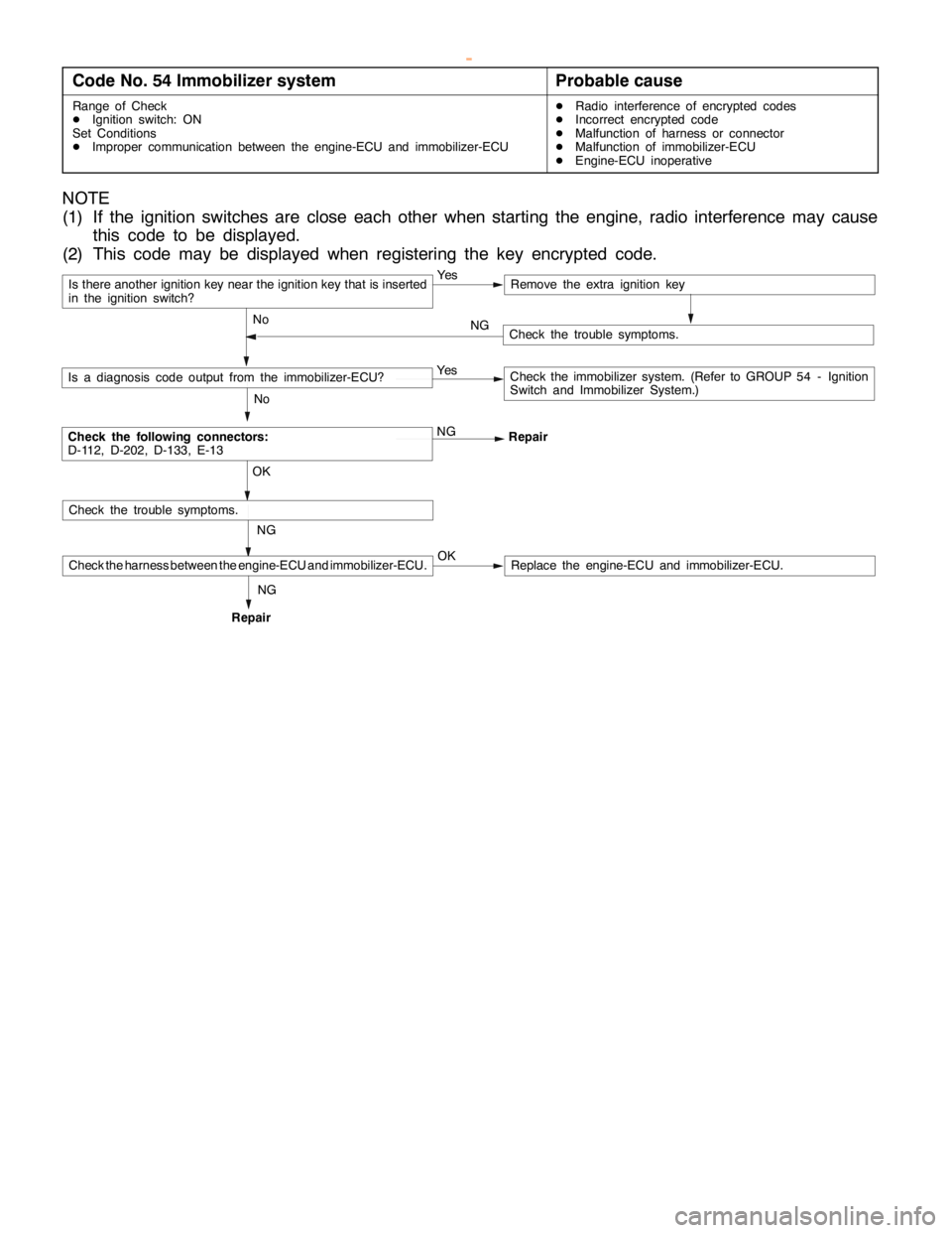
Code No. 54 Immobilizer systemProbable cause
Range of Check
DIgnition switch: ON
Set Conditions
DImproper communication between the engine-ECU and immobilizer-ECUDRadio interference of encrypted codes
DIncorrect encrypted code
DMalfunction of harness or connector
DMalfunction of immobilizer-ECU
DEngine-ECU inoperative
NOTE
(1) If the ignition switches are close each other when starting the engine, radio interference may cause
this code to be displayed.
(2) This code may be displayed when registering the key encrypted code.
Is there another ignition key near the ignition key that is inserted
in the ignition switch?Ye sRemove the extra ignition key
No
Check the following connectors:
D-112, D-202, D-133, E-13NG
Repair
No
Is a diagnosis code output from the immobilizer-ECU?Ye sCheck the immobilizer system. (Refer to GROUP 54 - Ignition
Switch and Immobilizer System.)
NG OK
Check the trouble symptoms.
Check the harness between the engine-ECU and immobilizer-ECU.OKReplace the engine-ECU and immobilizer-ECU.
Check the trouble symptoms. NG
RepairNG
www.WorkshopManuals.co.uk
Purchased from www.WorkshopManuals.co.uk
Page 1573 of 1839

54A-3
ON-VEHICLE SERVICE 46......................
Room Lamp Delay-off Time Adjustment
Procedure 46...............................
REAR COMBINATION LAMP 47...........
SPECIAL TOOLS 47...........................
TROUBLESHOOTING 47.......................
REAR COMBINATION LAMP 47................
HIGH-MOUNTED STOP LAMP 48.........
COLUMN SWITCH 48....................
SPECIAL TOOLS 48...........................
COLUMN SWITCH 48..........................
HAZARD WARNING LAMP SWITCH 50....
SPECIAL TOOLS 50...........................
HAZARD WARNING LAMP SWITCH 50.........
HORN 51................................
CIGARETTE LIGHTER 51.................
ACCESSORY SOCKET 51................
RHEOSTAT 52...........................
CLOCK OR CENTER DISPLAY 53........
TROUBLESHOOTING 53.......................
CLOCK OR CENTER DISPLAY 67..............
RADIO/TAPE PLAYER 68.................
TROUBLESHOOTING 68.......................
RADIO AND CD AUTO CHANGER 81..........
FRONT SPEAKERS 82...................
REAR SPEAKERS 82.....................
ANTENNA83 ............................DEFOGGER 86...........................
TROUBLESHOOTING
ON-VEHICLE SERVICE 86.....................
Printed Heater Check 86.....................
Defogger Relay Continuity Check 86...........
DEFOGGER SWITCH 87.......................
SMART WIRING SYSTEM (SWS)
Refer to GROUP 54B ....................
RADIATOR (RADIATOR FAN MOTOR)
Refer to GROUP 14 ......................
AUTOMATIC TRANSMISSION
Refer to GROUP 23 ......................
ANTI-LOCK BRAKE SYSTEM (ABS)
Refer to GROUP 35B ....................
DOOR HANDLE LATCH (DOOR LOCK)
Refer to GROUP 42 ......................
DOOR GLASS-REGULATOR (POWER
WINDOWS)
Refer to GROUP 42 ......................
KEYLESS ENTRY SYSTEM
Refer to GROUP 42 ......................
WINDSHIELD WIPER/WASHER
Refer to GROUP 51 ......................
REAR WIPER/WASHER
Refer to GROUP 51 ......................
SRS AIRBAG Refer to GROUP 52B......
HEATER Refer to GROUP 55.............
AIR CONDITIONER Refer to GROUP 55...
www.WorkshopManuals.co.uk
Purchased from www.WorkshopManuals.co.uk
Page 1634 of 1839
CHASSIS ELECTRICAL -Clock or Center Display54A-64
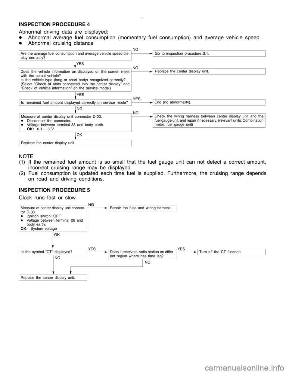
INSPECTION PROCEDURE 4
Abnormal driving data are displayed:
DAbnormal average fuel consumption (momentary fuel consumption) and average vehicle speed
DAbnormal cruising distance
Are the average fuel consumption and average vehicle speed dis-
play correctly?NOGo to inspection procedure 3.1.
YES
Does the vehicle information on displayed on the screen meet
with the actual vehicle?
Is the vehicle type (long or short body) recognized correctly?
(Select “Check of units connected into the center display” and
“Check of vehicle information” on the service mode.)NOReplace the center display unit.
YES
Is remained fuel amount displayed correctly on servicemode?YESEnd (no abnormality).
NO
Measure at center display unit connector D-03.
DDisconnect the connector.
DVoltage between terminal 33 and body earth.
OK:0.1 - 3 VNGCheck the wiring harness between center display unit and the
fuel gauge unit, and repair ifnecessary. (relevant units: Combination
meter, fuel gauge unit)
OK
Replace the center display unit.
NOTE
(1) If the remained fuel amount is so small that the fuel gauge unit can not detect a correct amount,
incorrect cruising range may be displayed.
(2) Fuel consumption is updated each time fuel is supplied. Furthermore, the cruising range depends
on road and driving conditions.
INSPECTION PROCEDURE 5
Clock runs fast or slow.
NGRepair the fuse and wiring harness.
OK
YES
Does it receive a radio station on differ-
ent region where has timelag?YESTurn off the CT function.
NO
Replace the center display unit.
Measure at center display unit connec-
tor D-03.
DIgnition switch: OFF
DVoltage between terminal 26 and
body earth.
OK:System voltage
Is the symbol “CT” displayed?
NO
www.WorkshopManuals.co.uk
Purchased from www.WorkshopManuals.co.uk
Page 1638 of 1839

CHASSIS ELECTRICAL -Radio/Tape Player54A-68
RADIO/TAPE PLAYER
TROUBLESHOOTING
QUICK-REFERENCE TROUBLESHOOTING CHART
ItemsProblem symptomRelevant chart
NoiseNoise appears at certain places when travelling.A-1
Mixed with noise, only at night.A-2
Broadcasts can be heard but UKW/MW/LW has a lot of noise.A-3
There is noise when starting the engine.A-4
Some noise appears when there is vibration or shocks during
travelling.A-5
Ever-present noise.A-6
RadioWhen switch is set to ON, no power is available.B-1
No sound from one speaker.B-2
There is noise but no reception for UKW/MW/LW or no sound from
UKW/MW/LW.B-3
Insufficient sensitivity.B-4
Distortion on UKW/MW/LW.B-5
Too few automatic select stations.B-6
Insufficient memory (preset stations are erased).B-7
Tape playerCassette tape will not be inserted.C-1
No sound.C-2
No sound from one speaker.C-3
Sound quality is poor, or sound is weak.C-4
Cassette tape will not be ejected.C-5
Uneven revolution. Tape speed is fast or slow.C-6
Faulty auto reverse.C-7
Tape gets caught in mechanism.C-8
www.WorkshopManuals.co.uk
Purchased from www.WorkshopManuals.co.uk
Page 1639 of 1839
CHASSIS ELECTRICAL -Radio/Tape Player54A-69
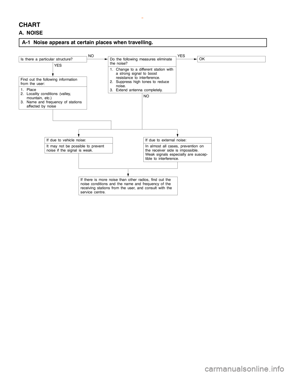
CHART
A. NOISE
A-1 Noise appears at certain places when travelling.
Is there a particular structure?NODo the following measures eliminate
the noise?
1. Change to a different station with
a strong signal to boost
resistance to interference.
2. Suppresshightones to reduce
noise.
3. Extend antenna completely.YESOK
YES
Find out the following information
from the user:
1. Place
2. Locality conditions (valley,
mountain, etc.)
3. Name and frequency of stations
affected by noiseNO
If due to vehicle noise:
It may not be possible to prevent
noise if the signal is weak.
If there is more noise than other radios, find out the
noise conditions and thename andfrequency of the
receiving stations from the user, and consult with the
service centre.
If due to external noise:
In almost all cases, prevention on
the receiver side is impossible.
Weak signals especially are suscep-
tible to interference.
www.WorkshopManuals.co.uk
Purchased from www.WorkshopManuals.co.uk