2000 MITSUBISHI MONTERO clutch
[x] Cancel search: clutchPage 168 of 1839

ENGINE <4M4> -Cylinder Head Gasket11C-27
CYLINDER HEAD GASKET
REMOVAL AND INSTALLATION
Pre-removal and Post-installation Operation
DEngine Coolant Drain and Refill
(Refer to GROUP 14 - On-vehicle Service.)
DEngine Oil Check andRefill
(Refer to GROUP 12 - On-vehicle Service.)
DFuel Line Air-bleeding
(Refer to GROUP 13C - On-vehicle Service.)
DDrive Belt TensionCheck and Adjustment
(Refer to P.11C-5.)
(Refer to P.11C-20.)
DCooling Fan and Fan Clutch Assembly Removal and
Installation (Refer to GROUP 14.)
DIntake Manifold Removal and Installation
(Refer to GROUP15.)
DTurbocharger Removal and Installation
(Refer to GROUP15.)
DExhaust Manifold Removal and Installation
(Refer to GROUP15.)
www.WorkshopManuals.co.uk
Purchased from www.WorkshopManuals.co.uk
Page 216 of 1839

13A-2
GASOLINE DIRECT
INJECTION (GDI)
CONTENTS
GENERAL INFORMATION 3..................
SERVICE SPECIFICATIONS 7.................
SEALANT 7..................................
SPECIAL TOOLS 7..........................
TROUBLESHOOTING
TROUBLESHOOTING 126.............
ON-VEHICLE SERVICE 219..................
Fuel Pump Connector Disconnection (How to
Reduce the Fuel Pressure) 219.................
Fuel Pump Operation (Low Pressure) Check 220.
Throttle Body (Throttle Valve Area) Cleaning 220.
Throttle Position Sensor Adjustment 220.........
Accelerator Pedal Position Sensor
Adjustment 221................................
Fuel Pressure Test 222.........................
Fuel Leak Check 225...........................
Component Location 226........................
Engine Control Relay, Fuel Pump Relay, Injector
Driver Control Relay and Throttle Valve Control
Servo Relay Continuity Check 227...............Intake Air Temperature Sensor Check 227.......
Engine Coolant Temperature Sensor Check 227..
Throttle Position Sensor Check 228..............
Accelerator Pedal Position Sensor Check 229....
Accelerator Pedal Position Switch Check 230.....
Oxygen Sensor Check 230......................
Injector Check 232.............................
Throttle Valve Control Servo Check 232..........
Clutch Switch Check 233.......................
Purge Control Solenoid Valve Check 233.........
EGR Valve Check 233..........................
INJECTOR 234.............................
FUEL PUMP (HIGH PRESSURE) 239.........
THROTTLE BODY 242.......................
INJECTOR DRIVER 245.....................
ENGINE-ECU, ENGINE-A/T-ECU ,
THROTTLE VALVE CONTROLLER 246.......
www.WorkshopManuals.co.uk
Purchased from www.WorkshopManuals.co.uk
Page 218 of 1839

GDI -General Information13A-4
SELF-DIAGNOSIS FUNCTION
DWhen an abnormality is detected in one
of the sensors or actuators related to
emission control, the engine warning lamp
(check engine lamp) illuminates or flashes
as a warning to the driver.
DWhen an abnormality is detected in one
of the sensors or actuators, a diagnosis
code corresponding to the abnormality is
output.
DThe engine-ECU records the engine
operating condition when the diagnosis
code is set. This data is called “freezeframe” data.
This data can be read by using the MUT-II,
and can then be used in simulation tests
for troubleshooting.
DThe RAM data inside the engine-ECU
related to the sensors and actuators can
be read by means of the MUT-II. In addition,
the actuators can be force-driven under
certain circumstances.
OTHER CONTROL FUNCTIONS
1. Fuel Pump Control
Turns the fuel pump relay ON so that current
is supplied to the fuel pump while the engine
is cranking or running.
2. A/C Relay Control
Turns the compressor clutch of the A/C
ON and OFF.3. Purge Control Solenoid Valve Control
Refer to GROUP 17.
4. EGR Control Servo Control
Refer to GROUP 17.
GENERAL SPECIFICATIONS
ItemsSpecifications
Throttle bodyThrottle bore mm65
Throttle position sensorVariable resistor type
Throttle valve control servoBrushless DC-motor type
Engine-ECUIdentification model No.E2T79271
E2T79272
Engine-Identification model No.E2T76277
A/T-ECU
E2T76278
www.WorkshopManuals.co.uk
Purchased from www.WorkshopManuals.co.uk
Page 286 of 1839

GDI -Troubleshooting
INSPECTION CHART FOR TROUBLE SYMPTOMS
Trouble symptomInspection
procedure
No.Reference page
CommunicationCommunication with all systems is not possible.113A-74
with MUT-IIis
impossible.
Communication with engine-ECU only is not possible.213A-75
Engine warning
lamp andThe engine warning lamp does not illuminate right after the
ignition switch is turned to the ON position.313A-76
related parts
The engine warning lamp remains illuminating and never goes
out.413A-76
StartingNo initial combustion (starting impossible)513A-77
Initial combustion but no complete combustion
(starting impossible)613A-79
Long time to start (improper starting)
Idling stabilityUnstable idling (Rough idling, hunting)713A-81
(Improper idling)
Idling speed is high. (Improper idling speed)813A-83
Idling speed is low. (Improper idling speed)
Idling stabilityWhen the engine is cold, it stalls at idling. (Die out)913A-84
(Engine stalls)
When the engine is hot, it stalls at idling. (Die out)1013A-85
The engine stalls when starting the car. (Pass out)1113A-87
The engine stalls when decelerating.1213A-88
DrivingHesitation, sag or stumble1313A-89
Poor acceleration
Surge
The feeling of impact or vibration when accelerating1413A-90
The feeling of impact or vibration when decelerating1513A-91
Knocking1613A-91
Dieseling1713A-91
Too high CO and HC concentration when idling1813A-92
Low alternator output voltage (approx. 12.3 V)1913A-94
Engine idle speed is incorrect while the A/C is on.2013A-94
A/C condenser fan is inoperative2113A-95
Clutch switch system malfunction2213A-96
GDI ECO indi-GDI ECO indicator lamp does not illuminate.2313A-96
cator lamp sys-
tem
GDI ECO indicator lamp remains illuminated and does not go off.2413A-97
www.WorkshopManuals.co.uk
Purchased from www.WorkshopManuals.co.uk
Page 310 of 1839

GDI -Troubleshooting
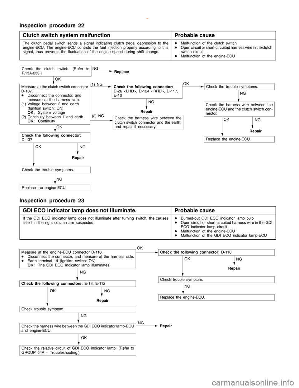
Inspection procedure 22
Clutch switch system malfunction
Probable cause
The clutchpedalswitch sends a signal indicating clutchpedal depression to the
engine-ECU. The engine-ECU controls the fuel injection properly according to this
signal, thus prevents the fluctuation of theenginespeed during shift change.DMalfunction of the clutch switch
DOpen circuit or short-circuited harness wire in the clutch
switch circuit
DMalfunction of the engine-ECU
NG
Repair
NG
Repair
OK
Replace the engine-ECU.
(2) NG
OK
Check the trouble symptoms.
NG
Replace the engine-ECU.
OK
Check the following connector:
D-137
Check the harness wire between the
clutch switch connector and the earth,
and repair if necessary.
Check the trouble symptoms.
Check the harness wire between the
engine-ECU and the clutch switch con-
nector.
Measure at the clutch switch connector
D-137.
DDisconnect the connector, and
measure at the harness side.
(1) Voltage between 2 and earth
(Ignition switch: ON)
OK:
System voltage
(2) Continuity between 1 and earth
OK:
Continuity(1) NGCheck the following connector:
D-26
E-10OK NG
Replace
Repair
OK
Check the clutch switch. (Refer to
P.13A-233.)
NG
NG
Inspection procedure 23
GDI ECO indicator lamp does not illuminate.
Probable cause
If the GDI ECO indicator lampdoes notilluminate after turningswitch, the causes
listed in the right column are suspected.DBurned-out GDI ECO indicator lamp bulb
DOpen circuit or short-circuited harness wire in the GDI
ECO indicator lampcircuit
DMalfunction of the engine-ECU
DMalfunction of the GDI ECO indicator lamp-ECU
NG
Repair
Measure at the engine-ECU connector D-116.
DDisconnect the connector, and measure at the harness side.
DEarth terminal 14 (Ignition switch: ON)
OK:
The GDI ECO indicator lamp illuminates.OKCheck the following connector:
D-116
OK
Check trouble symptom.
NG
Replace the engine-ECU.
NG
Check the following connectors:
E-13, E-112
Check trouble symptom.
Check the harness wire between the GDI ECO indicator lamp-ECU
and engine-ECU.
Check the relative circuit of GDI ECO indicatorlamp.(Refer to
GROUP 54A - Troubleshooting.)NG OK
OK NG
NG
Repair
Repair
www.WorkshopManuals.co.uk
Purchased from www.WorkshopManuals.co.uk
Page 316 of 1839

GDI -Troubleshooting
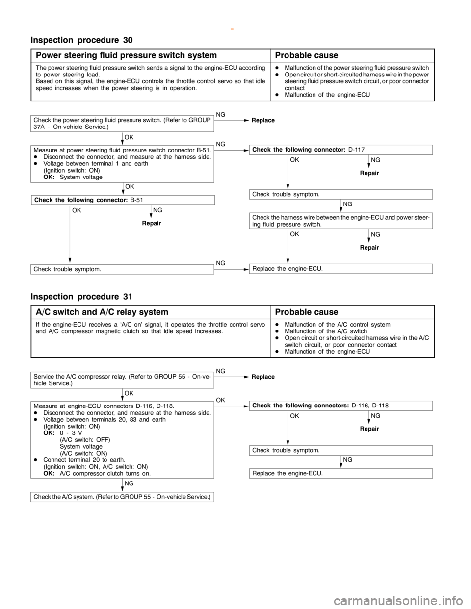
Inspection procedure 30
Power steering fluid pressure switch system
Probable cause
The power steering fluid pressure switch sends a signal to the engine-ECU according
to power steering load.
Based on this signal, the engine-ECU controls the throttle control servo so thatidle
speed increases when the power steering is in operation.DMalfunction of the power steering fluid pressure switch
DOpen circuit or short-circuited harness wire in the power
steering fluid pressure switch circuit, or poor connector
contact
DMalfunction of the engine-ECU
NG
NG
RepairOK
Replace the engine-ECU.
NG
Repair
Check the power steering fluid pressure switch. (Refer to GROUP
37A - On-vehicle Service.)NG
Replace
OK
Measure at power steering fluid pressure switch connector B-51.
DDisconnect the connector, and measure at the harness side.
DVoltage between terminal 1 and earth
(Ignition switch: ON)
OK:
System voltageNGCheck the following connector:
D-117
OK
Check trouble symptom.
Check the harness wire between the engine-ECU and power steer-
ing fluid pressure switch.NG
RepairOK
OK
Check the following connector:
B-51
Check trouble symptom.NG
Inspection procedure 31
A/C switch and A/C relay system
Probable cause
If the engine-ECU receives a ‘A/C on’ signal, it operates the throttle control servo
and A/C compressor magnetic clutch so thatidlespeed increases.DMalfunction of the A/C control system
DMalfunction of the A/C switch
DOpen circuit or short-circuited harness wire in the A/C
switch circuit, or poor connector contact
DMalfunction of the engine-ECU
NG
NG
RepairOK
Check trouble symptom.
NG
Replace the engine-ECU.
Service the A/C compressor relay. (Refer to GROUP 55 - On-ve-
hicle Service.)NG
Replace
OK
Measure at engine-ECU connectors D-116, D-118.
DDisconnect the connector, and measure at the harness side.
DVoltage between terminals 20, 83 and earth
(Ignition switch: ON)
OK:
0-3V
(A/C switch: OFF)
System voltage
(A/C switch: ON)
DConnect terminal 20 to earth.
(Ignition switch: ON, A/C switch: ON)
OK:
A/C compressor clutch turns on.OKCheck the following connectors:
D-116, D-118
Check the A/C system. (Refer to GROUP 55 - On-vehicle Service.)
www.WorkshopManuals.co.uk
Purchased from www.WorkshopManuals.co.uk
Page 322 of 1839

GDI -Troubleshooting
Item
No.Reference
page Inspection
procedure
No. Normal condition Requirements Check items
41Injector drive
time *2DEngine coolant
temperature:
80 - 95_CIdling0.3 - 0.8 ms*1--
80 - 95_C
DLamps, electric
cooling fan and
all accessories:
2,500 r/min0.4 - 1.0 ms
all accessories:
OFF
DTransmission:
Neutral
Sudden racingIncreases
44Ignition
advanceDEngine: After
warm-upIdling5-20_BTDC *1Code No.
P030013A-53
advancewarm-up
DSet a timing
light.
2,500 r/min15 - 35_BTDC
P0300
49A/C relayEngine: After
warm-up, idlingA/C switch: OFFOFF (compressor
clutch is not oper-
ating)Procedure
No.3113A-102
A/C switch: ONON (compressor
clutch is operating)
59Oxygen sen-
sor (rear)DTransmission:
2nd gear
DDrive with
throttle widely
open3,500 r/min600 - 1,000 mVCode No.
P013613A-31
67Stop lamp
switchIgnition switch: ONBrake pedal: De-
pressedOFFProcedure
No.3213A-103
Brake pedal: Re-
leasedON
68EGR valveDEngine coolant
temperature:
80 - 95_C
DLamps, electricIdling2 - 20 STEPCode No.
P040313A-60
cooling fan and
all accessories:
OFF
DTransmission:
Neutral
2,500 r/min0 - 10 STEP
74Fuel pressure
sensorDEngine coolant
temperature:
80 - 95_C
DLamps, electric
cooling fan and
all accessories:
OFF
DTransmission:
NeutralEngine: Idling4 - 6.9 MPaCode No.
P019013A-36
www.WorkshopManuals.co.uk
Purchased from www.WorkshopManuals.co.uk
Page 328 of 1839

GDI -Troubleshooting
Terminal
No.Normal condition Check requirements (engine condition) Check item
63Stop lamp switchDepress the brake pedal.System voltage
Release the brake pedal.0-3V
65A/C switch (2nd channel)Refer to GROUP 55 - Troubleshooting “Check at the A/C-ECU
terminal, engine-ECU output terminals.”
66Clutch switchDepress the clutch pedal.0-3V
Release the clutch pedal.System voltage
68Ignition switch-STEngine: Cranking8V or more
71Oxygen sensor (front)Engine: Warm up, and then hold the
engine speed at 2,500r/min (Use a
digital voltmeter).0«0.8 V alternates.
76Air flow sensor reset signalEngine: Idling0-1V
Engine: 3,000 r/min6-9V
78Throttle position sensor
(2nd channel)Ignition switch:
ONRelease the
accelerator pedal.4.5 - 5.5 V
Depress the
accelerator pedal
fully.0.4 - 0.6 V
79Accelerator pedal position
switchIgnition switch:
ONRelease the
accelerator pedal.0-1V
Depress the
accelerator pedal
fully.4V or more
80Vehicle speed sensorDIgnition switch: ON
DMove the vehicle forward.0«system voltage
alternates.
83A/C switch (1st channel)Engine: IdlingA/C switch: OFF0-3V
A/C switch: ON
(Compressor is
operating)System voltage
88Small lamp switchLighting switch: OFF0-3V
Lighting switch: ON (Taillamp: ON)System voltage
89Oxygen sensor heaterEngine: Idling0-3V
(front)
Engine: 3,500 r/minSystem voltage
90Oxygen sensor heaterEngine: Idling0-3V
(rear)
Engine: 3,500 r/minSystem voltage
92Fuel pressure sensorEngine: Idling0.3 - 4.7 V
www.WorkshopManuals.co.uk
Purchased from www.WorkshopManuals.co.uk