2000 MITSUBISHI MONTERO turn signal
[x] Cancel search: turn signalPage 217 of 1839

GDI -General Information13A-3
GENERAL INFORMATION
The Gasoline Direct Injection System consists
of sensors which detect the engine conditions,
the engine-ECU
which controls the system based on
signals from these sensors, and actuators
which operate under the control of the
engine-ECU
carries out activities such as fuel injection
control, idle speed control and ignition timing
control. In addition, the engine-ECU
engine-A/T-ECU is equipped with several
diagnosis modes which simplify troubleshooting
when a problem develops.
FUEL INJECTION CONTROL
The injector drive times and injector timing are
controlled so that the optimum air/fuel mixture
is supplied to the engine to correspond to the
continually-changing engine operation condi-
tions.
A single injector for each cylinder is mounted
at the cylinder head. The fuel is sent under
pressure from the fuel tank to the fuel pressure
regulator (low pressure) by the fuel pump (low
pressure). The pressure is regulated by the
fuel pressure regulator (low pressure) and the
fuel regulated is then sent to the fuel pump
(high pressure). The fuel under increased
pressure generated by the fuel pump (high
pressure) is then regulated by the fuel pressure
regulator (high pressure) and is then distributed
to each of the injectors via the delivery pipes.Fuel injection is normally carried out once for
each cylinder for every two rotations of the
crankshaft. The firing order is 1-2-3-4-5-6. This
is called sequential fuel injection.
When the engine is cold or under a severe
load, the “open-loop” control keeps the air/fuel
ratio at a richer than usual level to maintain
driveability. When the engine is under low or
medium loads, the air/fuel ratio becomes leaner
to reduce fuel consumption. When the engine
is running at medium or high loads after having
warmed up, the “closed-loop” control uses the
signal from the oxygen sensor to keep the
air/fuel ratio at the optimum theoretical level.
THROTTLE VALVE OPENING ANGLE CONTROL
This system controls throttle valve opening
angle electronically. The engine-ECU
or engine-A/T-ECU determines how
deeply the accelerator pedal is depressed by
means of the accelerator position sensor (APS).
Then the engine-ECU
throttle valve opening angle to the throttle valve
controller. The throttle valve control servo
operates the throttle valve so that it reaches
the target opening angle.
IDLE SPEED CONTROL
This system maintains engine idle speed at
a predetermined condition by controlling the
air flow that passes through the throttle valve
according to engine idling condition and engine
loads at idling.
The engine-ECU
operates the throttle valve control servoso that engine speed is maintained within a
map value. The map value is predetermined
according to engine coolant temperature and
air-conditioning load.
IGNITION TIMING CONTROL
The power transistor located in the ignition
primary circuit turns ON and OFF to control
the primary current flow to the ignition coil. This
controls the ignition timing in order to provide
the optimum ignition timing with respect to the
engine operating conditions. The ignition timingis determined by the engine-ECU
engine-A/T-ECU from the engine speed,
intake air volume, engine coolant temperature,
atmospheric pressure and injection timing
(intake stroke or compression stroke).
www.WorkshopManuals.co.uk
Purchased from www.WorkshopManuals.co.uk
Page 227 of 1839

GDI -Troubleshooting
FAIL-SAFE FUNCTION REFERENCE TABLE
When the main sensor malfunctions are detected by the diagnosis function, the vehicle is controlled
by means of the pre-set control logic to maintain safe conditions for driving.
Malfunctioning itemControl contents during malfunction
Air flow sensor1. Suspends lean burn operation.
2. Uses the throttle position sensor signal and engine speed signal (crank angle
sensor signal) to take reading of the basic injector drive time and basic ignition
timing from the pre-set mapping.
Intake air temperature sensorControls as if the intake air temperature is 25_
C.
Throttle position sensor (2nd
channel)1. Suspends lean burn operation.
2. Controls the throttle opening angle feedback (half as much as the opening
rate in the normal condition) by using signals from the throttle position sensor
(1st channel). However, this controlling system is not applied if the throttle
position sensor (1st channel) and throttle position sensor (2nd channel)
combination output voltage is outside 4 - 6 V.
3. Refrains from controlling the throttle opening angle feedback if the throttle
position sensor (1st channel) is also defective.
Engine coolant temperature
sensorControls as if the engine coolant temperature is 80_
C. (Moreover, the control system
is working until the ignition switch is turned OFF if the sensor signal returns to normal.)
Camshaft position sensorCuts the fuel supply once a malfunction is detected. (Only when there has been
no occasion of detecting No.1 cylinder top dead centre after the ignition switch
is turned ON.)
Vehicle speed sensor1. Suspends lean burn operation. However, the control is cancelled as a certain
time passes by with the engine speed of 1,500 r/min or more.
2. Suspends lean burn operation during the engine idling.
Barometric pressure sensorControls as if the barometric pressure is 101 kPa.
Detonation sensorFixes the ignition timing as that for standard petrol.
Injector1. Suspends lean burn operation.
2. Suspends the exhaust gas recirculation.
Ignition coil (incorporating pow-
er transistor)1. Suspends lean burn operation.
2. Cuts off the fuel supply to cylinders with an abnormal ignition signal.
Fuel pressure sensor1. Controls as if the fuel pressure is 5MPa.
2
. Suspends fuel injection. (when the low pressure is detected and the engine
speed is more than 3,000r/min)
Alternator FR terminalRefrains from controlling to suppress the alternator output to electrical load.
(Operated as a normal alternator)
Accelerator pedal position sen-
sor (2nd channel)1. Suspends lean burn operation.
2. Controls the throttle valve position by using signals from the accelerator pedal
position sensor (1st channel). (However, the control system is not applicable
if the difference from the accelerator pedal position sensor (1st channel) output
voltage is 1.0 V or higher.)
3
. Suspends the electronic controlled throttle valve system if accelerator pedal
position sensor (1st channel) is also defective.
www.WorkshopManuals.co.uk
Purchased from www.WorkshopManuals.co.uk
Page 310 of 1839

GDI -Troubleshooting
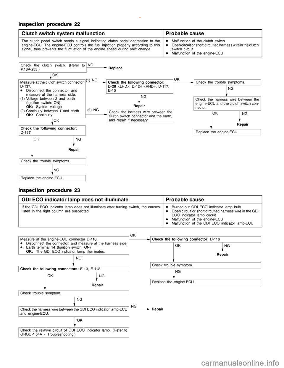
Inspection procedure 22
Clutch switch system malfunction
Probable cause
The clutchpedalswitch sends a signal indicating clutchpedal depression to the
engine-ECU. The engine-ECU controls the fuel injection properly according to this
signal, thus prevents the fluctuation of theenginespeed during shift change.DMalfunction of the clutch switch
DOpen circuit or short-circuited harness wire in the clutch
switch circuit
DMalfunction of the engine-ECU
NG
Repair
NG
Repair
OK
Replace the engine-ECU.
(2) NG
OK
Check the trouble symptoms.
NG
Replace the engine-ECU.
OK
Check the following connector:
D-137
Check the harness wire between the
clutch switch connector and the earth,
and repair if necessary.
Check the trouble symptoms.
Check the harness wire between the
engine-ECU and the clutch switch con-
nector.
Measure at the clutch switch connector
D-137.
DDisconnect the connector, and
measure at the harness side.
(1) Voltage between 2 and earth
(Ignition switch: ON)
OK:
System voltage
(2) Continuity between 1 and earth
OK:
Continuity(1) NGCheck the following connector:
D-26
E-10OK NG
Replace
Repair
OK
Check the clutch switch. (Refer to
P.13A-233.)
NG
NG
Inspection procedure 23
GDI ECO indicator lamp does not illuminate.
Probable cause
If the GDI ECO indicator lampdoes notilluminate after turningswitch, the causes
listed in the right column are suspected.DBurned-out GDI ECO indicator lamp bulb
DOpen circuit or short-circuited harness wire in the GDI
ECO indicator lampcircuit
DMalfunction of the engine-ECU
DMalfunction of the GDI ECO indicator lamp-ECU
NG
Repair
Measure at the engine-ECU connector D-116.
DDisconnect the connector, and measure at the harness side.
DEarth terminal 14 (Ignition switch: ON)
OK:
The GDI ECO indicator lamp illuminates.OKCheck the following connector:
D-116
OK
Check trouble symptom.
NG
Replace the engine-ECU.
NG
Check the following connectors:
E-13, E-112
Check trouble symptom.
Check the harness wire between the GDI ECO indicator lamp-ECU
and engine-ECU.
Check the relative circuit of GDI ECO indicatorlamp.(Refer to
GROUP 54A - Troubleshooting.)NG OK
OK NG
NG
Repair
Repair
www.WorkshopManuals.co.uk
Purchased from www.WorkshopManuals.co.uk
Page 313 of 1839

GDI -Troubleshooting
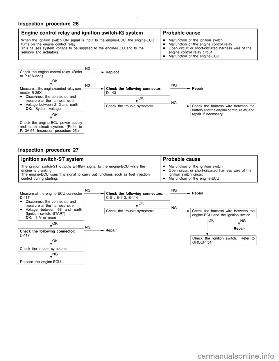
Inspection procedure 26
Engine control relay and ignition switch-IG system
Probable cause
When the ignition switch ON signal is input to the engine-ECU, the engine-ECU
turns on theengine controlrelay.
This causes system voltage to be supplied to the engine-ECU and to the
sensors and actuators.DMalfunction of the ignition switch
DMalfunction of the engine controlrelay
DOpen circuit or short-circuited harness wire of the
engine controlrelay circuit
DMalfunction of the engine-ECU
OK
Check the trouble symptoms.NGCheck the harness wire between the
battery and theengine controlrelay, and
repair if necessary.
OK
Check the engine-ECU power supply
and earth circuit system. (Refer to
P.13A-98, Inspection procedure 25.)
OK
Measure at the engine controlrelay con-
nector B-25X.
DDisconnect the connector, and
measure at the harness side.
DVoltage between 2, 3 and earth
OK:
System voltageNGCheck the following connector:
D-143NG
Repair
Check theengine controlrelay. (Refer
to P.13A-227.)NG
Replace
Inspection procedure 27
Ignition switch-ST system
Probable cause
The ignition switch-ST outputs a HIGH signal to the engine-ECU while the
engine iscranking.
The engine-ECU uses this signal to carry out functions such as fuel injection
control during starting.DMalfunction of the ignition switch
DOpen circuit or short-circuited harness wire of the
ignition switch circuit
DMalfunction of the engine-ECU
NG
RepairOK
Check the ignition switch. (Refer to
GROUP 54.)
NG
Replace the engine-ECU.
OK
Check the trouble symptoms.
OK
Check the following connector:
D-117NG
RepairOK
Check the trouble symptoms.NGCheck the harness wire between the
engine-ECU and the ignition switch.
Measure at the engine-ECU connector
D-117.
DDisconnect the connector, and
measure at the harness side.
DVoltage between 68 and earth
(Ignition switch: START)
OK:
8 V or moreNGCheck the following connectors:
C-01, E-113, E-114NG
Repair
www.WorkshopManuals.co.uk
Purchased from www.WorkshopManuals.co.uk
Page 316 of 1839

GDI -Troubleshooting
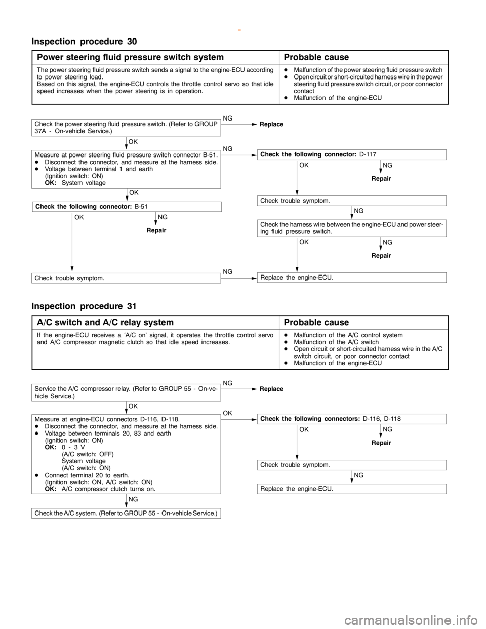
Inspection procedure 30
Power steering fluid pressure switch system
Probable cause
The power steering fluid pressure switch sends a signal to the engine-ECU according
to power steering load.
Based on this signal, the engine-ECU controls the throttle control servo so thatidle
speed increases when the power steering is in operation.DMalfunction of the power steering fluid pressure switch
DOpen circuit or short-circuited harness wire in the power
steering fluid pressure switch circuit, or poor connector
contact
DMalfunction of the engine-ECU
NG
NG
RepairOK
Replace the engine-ECU.
NG
Repair
Check the power steering fluid pressure switch. (Refer to GROUP
37A - On-vehicle Service.)NG
Replace
OK
Measure at power steering fluid pressure switch connector B-51.
DDisconnect the connector, and measure at the harness side.
DVoltage between terminal 1 and earth
(Ignition switch: ON)
OK:
System voltageNGCheck the following connector:
D-117
OK
Check trouble symptom.
Check the harness wire between the engine-ECU and power steer-
ing fluid pressure switch.NG
RepairOK
OK
Check the following connector:
B-51
Check trouble symptom.NG
Inspection procedure 31
A/C switch and A/C relay system
Probable cause
If the engine-ECU receives a ‘A/C on’ signal, it operates the throttle control servo
and A/C compressor magnetic clutch so thatidlespeed increases.DMalfunction of the A/C control system
DMalfunction of the A/C switch
DOpen circuit or short-circuited harness wire in the A/C
switch circuit, or poor connector contact
DMalfunction of the engine-ECU
NG
NG
RepairOK
Check trouble symptom.
NG
Replace the engine-ECU.
Service the A/C compressor relay. (Refer to GROUP 55 - On-ve-
hicle Service.)NG
Replace
OK
Measure at engine-ECU connectors D-116, D-118.
DDisconnect the connector, and measure at the harness side.
DVoltage between terminals 20, 83 and earth
(Ignition switch: ON)
OK:
0-3V
(A/C switch: OFF)
System voltage
(A/C switch: ON)
DConnect terminal 20 to earth.
(Ignition switch: ON, A/C switch: ON)
OK:
A/C compressor clutch turns on.OKCheck the following connectors:
D-116, D-118
Check the A/C system. (Refer to GROUP 55 - On-vehicle Service.)
www.WorkshopManuals.co.uk
Purchased from www.WorkshopManuals.co.uk
Page 321 of 1839

GDI -Troubleshooting
Item
No.Reference
page Inspection
procedure
No. Normal condition Requirements Check items
25BarometricIgnition switch: ONAltitude: 0 m101 kPaCode No.13A-19
pressure sen-
sor
Altitude: 600 m95 kPa
P0105
Altitude: 1,200 m88 kPa
Altitude: 1,800 m81 kPa
26Accelerator
pedal positionIgnition switch: ON
(Depress and re-Release the accel-
erator pedal.ONProcedure
No.2813A-100
switchlease the accelera-
tor pedal several
times)
Depress the accel-
erator pedal slight-
ly.OFF
27Power steer-
ing fluid pres-Engine: IdlingSteering wheel sta-
tionaryOFFProcedure
No.3013A-102
sure switch
Steering wheel
turningON
28A/C switchEngine: Idling (The
A/C compressor isA/C switch: OFFOFFProcedure
No.3113A-100
A/C compressor is
running when the
A/C switch is on.)
A/C switch: ONON
No.31
31Small lamp
switchEngine: IdlingLighting switch:
OFFOFFProcedure
No.3313A-104
Lighting switch: ONON
34Air flow sensorEngine: After hav-Engine is idlingONCode No.13A-17
reset signaling warmed up
3,000 r/minOFF
P0100
37Volumetric effi-
ciencyDEngine coolant
temperature:Engine is idling20 - 40%--
80 - 95_C
DLamps, electric
cooling fan and2,500 r/min10 - 30%
cooling fan and
all accessories:
OFF
DTransmission:
Neutral
Engine is suddenly
racedVolumetric effi-
ciency increases in
response to racing
38Crank angle
sensorDEngine: Cranking [reading is possible
at 2,000 r/min or less]
DTachometer: ConnectedEngine speeds dis-
played on the
MUT-IIand
tachometer are
identical.--
www.WorkshopManuals.co.uk
Purchased from www.WorkshopManuals.co.uk
Page 329 of 1839

GDI -Troubleshooting
Terminal
No.Normal condition Check requirements (engine condition) Check item
94Accelerator pedal position
sensor (1st channel)Ignition switch:
ONRelease the acceler-
ator pedal.0.3 - 1.0 V*1
Depress the
accelerator pedal
fully.4.2 - 5.5 V*2
96Injector open circuit check
signalEngine: Increase engine speed from
idle speed to 4,000 r/min.Decreases slightly (approx.
0.7V) from 4.5 V - 5.0 V.
99Ignition switch - IGIgnition switch: ONSystem voltage
NOTE
Check if the difference in output between *1 and *2 is 4 V or more.
CHECK CHART FOR RESISTANCE AND CONTINUITY
BETWEEN TERMINALS
1. Turn the ignition switch to OFF.
2. Disconnect the engine-ECU connector.
3. Measure the resistance and check for continuity between
the terminals of the engine-ECU harness-side connector
while referring to the check chart.
NOTE
(1) When measuring resistance and checking continuity,
a harness for checking contact pin pressure should
be used instead of inserting a test probe.
(2) Checking need not be carried out in the order given
in the chart.
Caution
If the terminals that should be checked are mistaken,
or if connector terminals are not correctly shorted
to earth, damage may be caused to the vehicle wiring,
sensors, engine-ECU and/or ohmmeter.
Be careful to prevent this!
4. If the ohmmeter shows any deviation from the standard
value, check the corresponding sensor, actuator and
related electrical wiring, and then repair or replace.
5. After repair or replacement, recheck with the ohmmeter
to confirm that the repair or replacement has corrected
the problem.
www.WorkshopManuals.co.uk
Purchased from www.WorkshopManuals.co.uk
Page 342 of 1839
