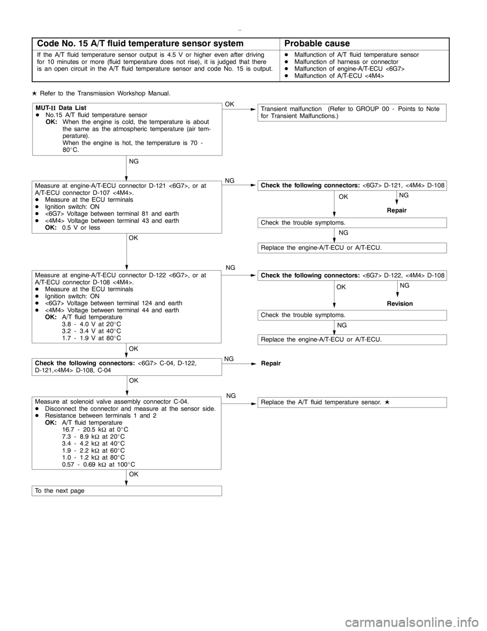
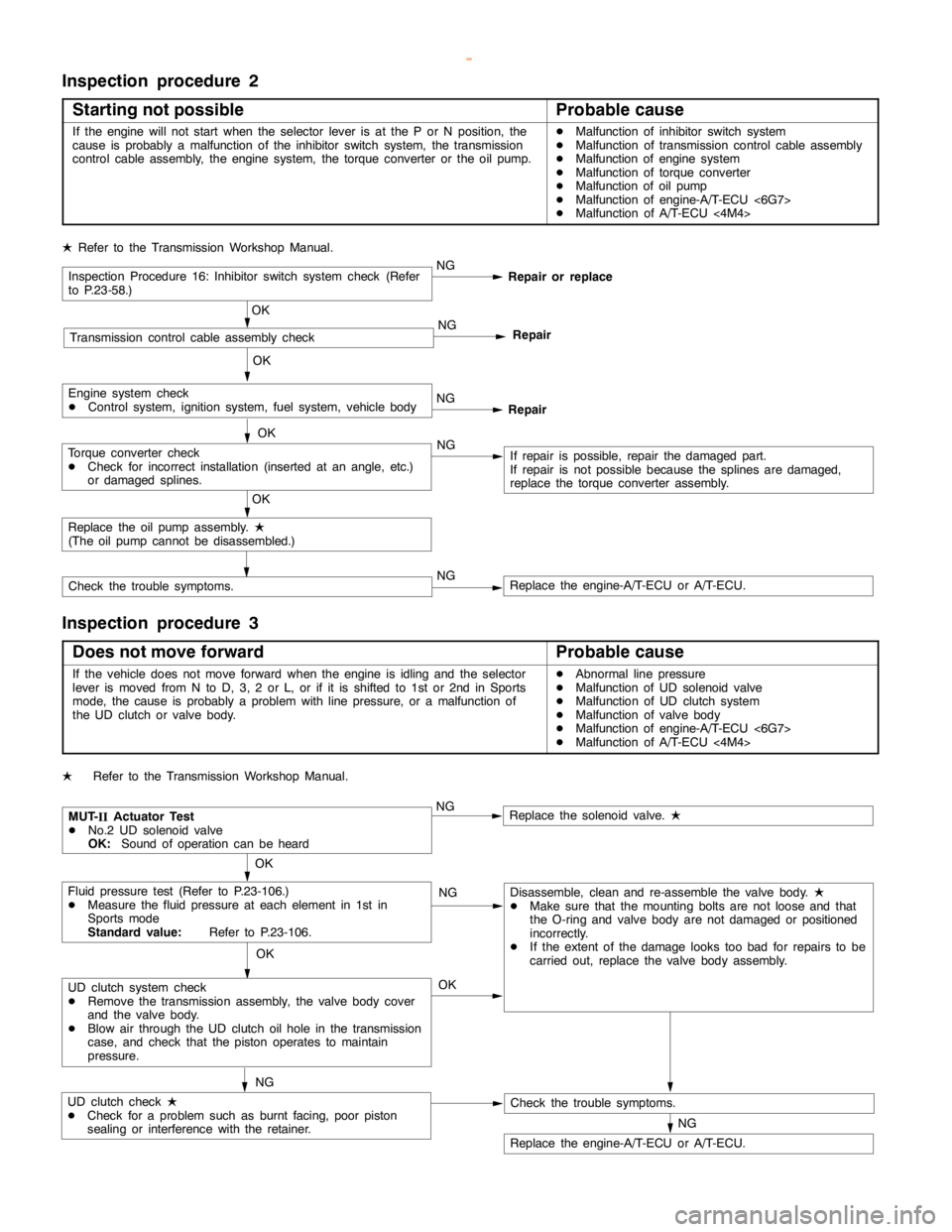
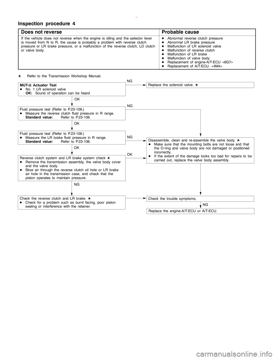
2000 MITSUBISHI MONTERO check transmission fluid
[x] Cancel search: check transmission fluidPage 321 of 1839

GDI -Troubleshooting
Item
No.Reference
page Inspection
procedure
No. Normal condition Requirements Check items
25BarometricIgnition switch: ONAltitude: 0 m101 kPaCode No.13A-19
pressure sen-
sor
Altitude: 600 m95 kPa
P0105
Altitude: 1,200 m88 kPa
Altitude: 1,800 m81 kPa
26Accelerator
pedal positionIgnition switch: ON
(Depress and re-Release the accel-
erator pedal.ONProcedure
No.2813A-100
switchlease the accelera-
tor pedal several
times)
Depress the accel-
erator pedal slight-
ly.OFF
27Power steer-
ing fluid pres-Engine: IdlingSteering wheel sta-
tionaryOFFProcedure
No.3013A-102
sure switch
Steering wheel
turningON
28A/C switchEngine: Idling (The
A/C compressor isA/C switch: OFFOFFProcedure
No.3113A-100
A/C compressor is
running when the
A/C switch is on.)
A/C switch: ONON
No.31
31Small lamp
switchEngine: IdlingLighting switch:
OFFOFFProcedure
No.3313A-104
Lighting switch: ONON
34Air flow sensorEngine: After hav-Engine is idlingONCode No.13A-17
reset signaling warmed up
3,000 r/minOFF
P0100
37Volumetric effi-
ciencyDEngine coolant
temperature:Engine is idling20 - 40%--
80 - 95_C
DLamps, electric
cooling fan and2,500 r/min10 - 30%
cooling fan and
all accessories:
OFF
DTransmission:
Neutral
Engine is suddenly
racedVolumetric effi-
ciency increases in
response to racing
38Crank angle
sensorDEngine: Cranking [reading is possible
at 2,000 r/min or less]
DTachometer: ConnectedEngine speeds dis-
played on the
MUT-IIand
tachometer are
identical.--
www.WorkshopManuals.co.uk
Purchased from www.WorkshopManuals.co.uk
Page 327 of 1839

GDI -Troubleshooting
Terminal
No.Normal condition Check requirements (engine condition) Check item
47Power supplyIgnition switch: ONSystem voltage
59
50Camshaft position sensorEngine: Cranking0.4 - 3.0 V
Engine: Idling0.5 - 2.0 V
51Barometric pressure sensorIgnition switch:Altitude: 0 m3.7 - 4.3 V
ON
Altitude: 1,200 m3.2 - 3.8 V
52Alternator FR terminalDEngine: Warm up, and then idling
DRadiator fan: not operating
DHeadlamp: OFF®ON
DStop lamp: OFF®ON
DRear defogger: OFF®ONVoltage decreases
53Oxygen sensor (rear)DTransmission: 2nd gear
DEngine speed: 3,500 r/min or more
DDriving with the throttle valve widely
open0.6 - 1.0 V
54Power steering fluid
pressure switchEngine: Warm
up, and thenSteering wheel
stationarySystem voltage
idling
Steering wheel
turning0-3V
55Injector driver relayIgnition switch: OFF0 - 0.1 V
Ignition switch: ON0.5 - 1.0 V
56Throttle valve control servoIgnition switch: OFF0 - 0.3 V
relay
Ignition switch: ON0.5 - 1.0 V
57Engine control relayIgnition switch: OFF0-3V
Ignition switch: ONSystem voltage
60Back-up power sourceIgnition switch: OFFSystem voltage
61Air flow sensorEngine: Idling2.2 - 3.2 V
Engine: 2,500 r/min
62Intake air temperature
sensorIgnition switch:
ONIntake air temper-
ature: 0_C3.2 - 3.8 V
Intake air temper-
ature: 20_C2.3 - 2.9 V
Intake air temper-
ature: 40_C1.5 - 2.1 V
Intake air temper-
ature: 80_C0.4 - 1.0 V
www.WorkshopManuals.co.uk
Purchased from www.WorkshopManuals.co.uk
Page 902 of 1839

Page 907 of 1839

Page 918 of 1839

Page 950 of 1839

Page 951 of 1839

Page 952 of 1839

AUTOMATIC TRANSMISSION -Troubleshooting AUTOMATIC TRANSMISSION -Troubleshooting 23-51
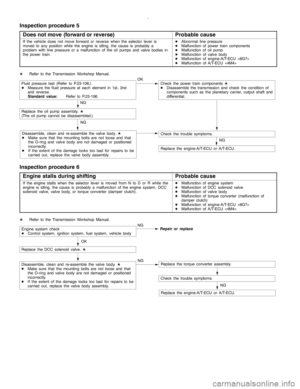
Inspection procedure 5
Does not move (forward or reverse)
Probable cause
If the vehicle does not move forward or reverse when the selector lever is
moved to any position while the engine is idling, thecause is probably a
problem with line pressure or a malfunction of the oil pumps and valve bodies in
the power train.DAbnormal line pressure
DMalfunction of power train components
DMalfunction of oil pump
DMalfunction of valve body
DMalfunction of engine-A/T-ECU <6G7>
DMalfunction of A/T-ECU<4M4>
LRefer to the Transmission Workshop Manual.
Fluid pressure test (Refer to P.23-106.)
DMeasure the fluid pressure at each element in 1st, 2nd
and reverse.
Standard value:Refer to P.23-106.OKCheck the power train components
L
DDisassemble the transmission and check the condition of
components such as the planetary carrier, output shaft and
differential.
NG
Replace the oil pumpassembly.
L
(The oilpump cannot be disassembled.)
Disassemble, clean and re-assemble the valve body.
L
DMake sure that the mounting bolts are not loose and that
the O-ring and valve body are notdamaged or positioned
incorrectly.
DIf the extent of thedamagelooks too bad for repairs to be
carried out, replace the valve body assembly.NG
NG
Check the trouble symptoms.
Replace the engine-A/T-ECU or A/T-ECU.
Inspection procedure 6
Engine stalls during shifting
Probable cause
If the enginestalls when the selector lever is moved from N to D or R while the
engine is idling, thecause is probably a malfunction of theenginesystem, DCC
solenoid valve, valve body, or torque converter (damper clutch).DMalfunction of enginesystem
DMalfunction of DCC solenoid valve
DMalfunction of valve body
DMalfunction of torque converter (malfunction of
damper clutch)
DMalfunction of engine-A/T-ECU <6G7>
DMalfunction of A/T-ECU<4M4>
LRefer to the Transmission Workshop Manual.
Engine system check
DControl system, ignition system, fuel system, vehicle bodyNG
Repair or replace
OK
Replace the DCC solenoid valve.
L
Disassemble, clean and re-assemble the valve body.
L
DMake sure that the mounting bolts are not loose and that
the O-ring and valve body are notdamaged or positioned
incorrectly.
DIf the extent of thedamagelooks too bad for repairs to be
carried out, replace the valve body assembly.NGReplace the torque converter assembly.
Check the trouble symptoms.
Replace the engine-A/T-ECU or A/T-ECU.NG
www.WorkshopManuals.co.uk
Purchased from www.WorkshopManuals.co.uk