2000 MITSUBISHI MONTERO cruise control
[x] Cancel search: cruise controlPage 228 of 1839

GDI -Troubleshooting
Malfunctioning item Control contents during malfunction
Accelerator pedal position sen-
sor (1st channel)1. Suspends lean burn operation.
2. Controls the throttle valve position by using signals from the accelerator pedal
position sensor (2nd channel). (However, this control is not applicable if the
voltage difference between the accelerator pedal position sensor (1st channel)
and accelerator pedal position sensor (2nd channel) is 1.0 V or higher.)
3. Also suspends the electronic-controlled throttle valve system when the
accelerator pedal position sensor (2nd channel) is defective.
Throttle position sensor (1st
channel)1. Suspends lean burn operation.
2.Controls throttle opening angle feedback by using signals from throttle position
sensor (2nd channel). (However, the controlling system is not applied when
the throttle position sensor (1st channel) and throttle position sensor (2nd
channel) combination output voltage is outside 4 - 6 V.)
3.Refrains from controlling the throttle opening angle feedback when throttle
position sensor (2nd channel) is also defective.
Electronic-controlled throttle
valve system1. Suspends the electronic controlled throttle valve system.
2. Suspends lean burn operation.
3. Suspends the idle speed feedback control.
Throttle valve position feed-
back1. Suspends the electronic controlled throttle valve system.
2. Suspends lean burn operation.
3. Suspends the engine speed feedback control.
However, if the throttle valve opening angle is significantly wide, this system carries
out the following controls.
1. Always cuts the fuel supply to three cylinders.
2. Cuts the fuel supply when the engine speed reaches 3,000 r/min or more.
Throttle control servo1. Suspends the electronic-controlled throttle valve system.
2. Suspends lean burn operation.
3. Suspends the engine speed feedback control.
Communication line between
the throttle valve controller and
the ECU1. Communication error between the throttle valve controller and the engine-ECU:
DSuspends lean burn operation.
DCuts the fuel supply when the engine speed reaches 3,000 r/min or
more.
DSuspends the cruise-control.
2. Communication error between the throttle valve controller and the engine-ECU:
DSuspends lean burn operation.
DCuts the fuel supply when the engine speed reaches 3,000 r/min or
more.
DSuspends the cruise-control.
DThe throttle valve controller controls the throttle valve opening angle by
using signals from accelerator pedal position sensor (2nd channel).
Throttle valve controller1. Suspends the electronic-controlled throttle valve system.
2. Suspends lean burn operation.
3. Suspends the engine speed feedback control.
NOTE
If the electronic-controlled throttle valve system is suspended, the engine warning lamp will illuminate.
www.WorkshopManuals.co.uk
Purchased from www.WorkshopManuals.co.uk
Page 343 of 1839

Page 497 of 1839

DIESEL FUEL <4M4> -Troubleshooting13C-6
FAIL-SAFE, BACKUP FUNCTIONS
When abnormalities in the major sensors are detected by diagnosis functions, pre-set control logic operates
to maintain a safe driving condition for the vehicle.
Diagnosis itemControl features in malfunction
Accelerator pedal position sensorD
Accelerator pedal released (idle switch ON)
Acceleration opening degree = 0%
D
Accelerator pedal applied (idle switchOFF)
Engine controlled at low speed
Acceleration opening degree = 20% fixed
Idle switchD
Void idling speed control.
D
Void cruise control.
Engine speed sensorD
Engine controlled at low speed
D
Void cruise control.
Boost air temperature sensorMaintain the intake air temperature at 50_
C.
Vehicle speed sensorD
Void idling speed control.
D
Void cruise control.
Engine coolant temperature sensorMaintain the engine coolant temperature at 80_
C.
Control sleeve position sensorD
Engine controlled at low speed
D
Void cruise control.
Timer piston position sensorD
Injection timing stabilizing control
D
Void cruise control.
Barometric pressure sensor (ECU
built-in)Keep the barometric pressure at 101 kPa.
Fuel temperature sensorMaintain the fuel temperature at 50_
C.
Boost pressure sensorKeep the boost pressure as barometric pressure (101 kPa).
Injection correction ROMVoid correction.
GE actuatorD
Engine controlled at low speed
D
Void cruise control.
Over boostVoid cruise control.
Timing control valveD
Injection timing stabilizing control
D
Void cruise control.
www.WorkshopManuals.co.uk
Purchased from www.WorkshopManuals.co.uk
Page 557 of 1839

DIESEL FUEL <4M4> -General/Service Specifications/Troubleshooting13C-2
GENERAL
OUTLINE OF CHANGES
Some service procedures have been established as the following changes have been made due to the
compliance with the Emission Regulation StepIII.
DThe intake manifold cover and injection pump cover have been reshaped.
DThe throttle body assembly has been changed.
DThe EGR valve assembly has been changed.
SERVICE SPECIFICATIONS
ItemStandard value
Throttle body assembly resistanceΩat - 10 - 50_C12 - 20
at 50 - 100_C12 - 23
TROUBLESHOOTING
FAIL-SAFE, BACKUP FUNCTIONS
When abnormalities in the major sensors are detected by diagnosis functions, pre-set control logic operates
to maintain a safe driving condition for the vehicle.
Diagnosis itemControl features in malfunction
Accelerator pedal position sensorDAccelerator pedal released (idle switch ON)
Acceleration opening degree = 0 %
DAccelerator pedal applied (idle switch OFF)
Engine controlled at low speed
Acceleration opening degree = 40 %
DVoid cruise control
Idle switchDVoid idling speed control
DVoid cruise control
Engine speed sensorDEngine controlled at low speed
DVoid cruise control
Boost air temperature sensorMaintain the intake air temperature at 50_C
Vehicle speed sensorDVoid idling speed control
DVoid cruise control
DWith accelerator pedal released (when idle switch is on)
Accelerator opening angle = 0 %
DWith accelerator pedal depressed (when idle switch is off)
Accelerator opening angle = Fixed at 40 % (M/T), 28 % (A/T)
Engine coolant temperature sensorMaintain the engine coolant temperature at 80_C (engine running), 0_C
(engine stopped or just started)
Control sleeve position sensorDWith accelerator pedal released (when idle switch is on)
Engine speed = 800 r/min
DWith accelerator pedal depressed (when idle switch is off)
Engine speed = 2,000 r/min
DVoid cruise control
Timer piston position sensorDOpen control by means of engine speed
DVoid cruise control
Barometric pressure sensor (ECU built-in)Keep the barometric pressure at 101 kPa
www.WorkshopManuals.co.uk
Purchased from www.WorkshopManuals.co.uk
Page 558 of 1839

DIESEL FUEL <4M4> -Troubleshooting13C-3
Diagnosis item Control features in malfunction
Fuel temperature sensorMaintain the fuel temperature at 90_C
Boost pressure sensorDKeep the boost pressure as barometric pressure (101 kPa)
DVoid cruise control
Injection correction ROMDWhen backup data is normal: Correction calculation using backup
data
DWhen backup data is corrupted: Fixed at correction value±0%
GE actuatorDWith accelerator pedal released (when idle switch is on)
Engine speed = 800 r/min
DWith accelerator pedal depressed (when idle switch is off)
Engine speed = 2,000 r/min
DVoid cruise control
Over boostVoid cruise control
Timing control valveDOpen control by means of engine speed
DVoid cruise control
Throttle body assemblyVoid cruise control
EGR sensorEGR control is prohibited
EGR motorEGR control is prohibited
INSPECTION CHART FOR DIAGNOSIS CODES
Code No.Diagnosis itemReference page
11Accelerator pedal position sensor system13C-4
12Boost pressure sensor (boost sensor) system13C-4
13Barometric pressure sensor system13C-4
18Engine speed sensor (backup) system13C-4
21Engine speed sensor system13C-5
23Idle switch (accelerator pedal position sensor built-in) system13C-5
27Accelerator pedal position sensor (sub) system13C-5
41Throttle valve system13C-6
46Injection correction ROM system13C-6
48GE actuator (in the middle of control sleeve position sensor inoperative) system13C-7
51EGR valve system13C-8
www.WorkshopManuals.co.uk
Purchased from www.WorkshopManuals.co.uk
Page 803 of 1839

17-1
ENGINE AND
EMISSION
CONTROL
CONTENTS
ENGINE CONTROL SYSTEM 3........
GENERAL INFORMATION 3................
SERVICE SPECIFICATIONS 3..............
ON-VEHICLE SERVICE 3..................
Accelerator Cable Check and Adjustment
<4D5> 3...................................
ACCELERAOR CABLE AND PADAL 4......
AUTO-CRUISE CONTROL SYSTEM 7..
GENERAL INFORMATION 7................
SPECIAL TOOL 8.........................
TROUBLESHOOTING 9....................
ON-VEHICLE SERVICE 27................
Auto-cruise Control Main Switch Check 27....
Auto-cruise Control Switch Check 28..........
Auto-cruise Control Component Check 29.....
AUTO-CRUISE CONTROL SWITCH 30.....
EMISSION CONTROL SYSTEM
<6G7> 31.............................
GENERAL INFORMATION 31..............
Emission Control Device Reference
Table 31....................................
SERVICE SPECIFICATIONS 32............
SPECIAL TOOL 32.......................
VACUUM HOSE 32.......................
Vacuum Hose Piping Diagram 32.............
Vacuum Circuit Diagram 33..................
Vacuum Hose Check 33.....................
Vacuum Hose Installation 33.................
CRANKCASE EMISSION CONTROL
SYSTEM 34..............................
General Information 34......................
System Diagram 34.........................
Component Location 34......................
Positive Crankcase Ventilation System
Check 35...................................
PCV Valve Check 35........................
CONTINUED ON NEXT PAGE
www.WorkshopManuals.co.uk
Purchased from www.WorkshopManuals.co.uk
Page 812 of 1839

ENGINE AND EMISSION CONTROL -Auto-cruise Control System17-10
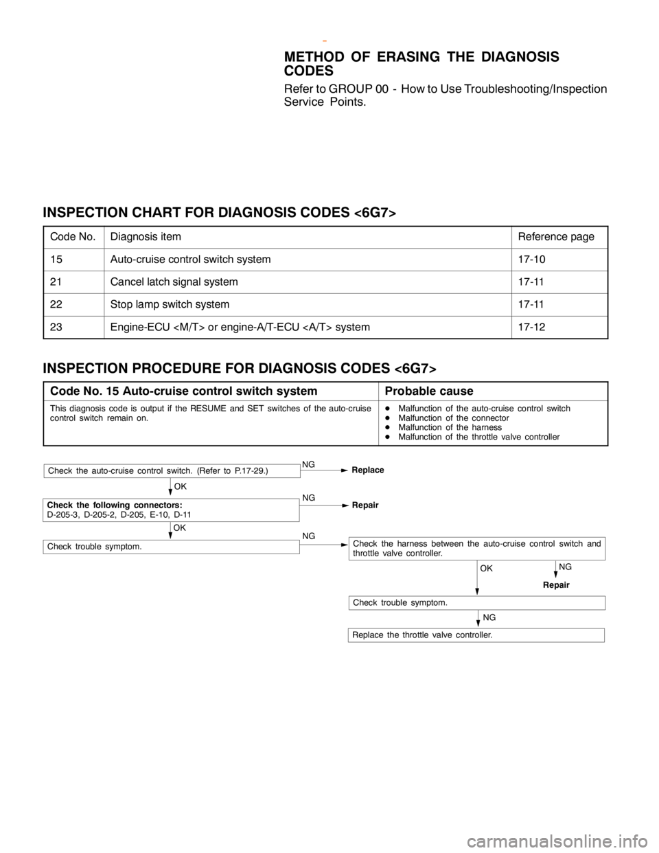
METHOD OF ERASING THE DIAGNOSIS
CODES
Refer to GROUP 00 - How to Use Troubleshooting/Inspection
Service Points.
INSPECTION CHART FOR DIAGNOSIS CODES <6G7>
Code No.Diagnosis itemReference page
15Auto-cruise control switch system17-10
21Cancel latch signal system17-11
22Stop lamp switch system17-11
23Engine-ECU
INSPECTION PROCEDURE FOR DIAGNOSIS CODES <6G7>
Code No. 15 Auto-cruise control switch systemProbable cause
This diagnosis code is output if the RESUME and SET switches of the auto-cruise
control switch remain on.DMalfunction of the auto-cruise control switch
DMalfunction of the connector
DMalfunction of the harness
DMalfunction of the throttle valve controller
Repair
Check the auto-cruise control switch. (Refer to P.17-29.)NG
Replace
OK
Check the following connectors:
D-205-3, D-205-2, D-205, E-10, D-11NG
Repair
NGCheck the harness between the auto-cruise control switch and
throttle valve controller.
NG
OK
Replace the throttle valve controller.
OK
Check trouble symptom.
Check trouble symptom.
NG
www.WorkshopManuals.co.uk
Purchased from www.WorkshopManuals.co.uk
Page 813 of 1839

ENGINE AND EMISSION CONTROL -Auto-cruise Control System17-11
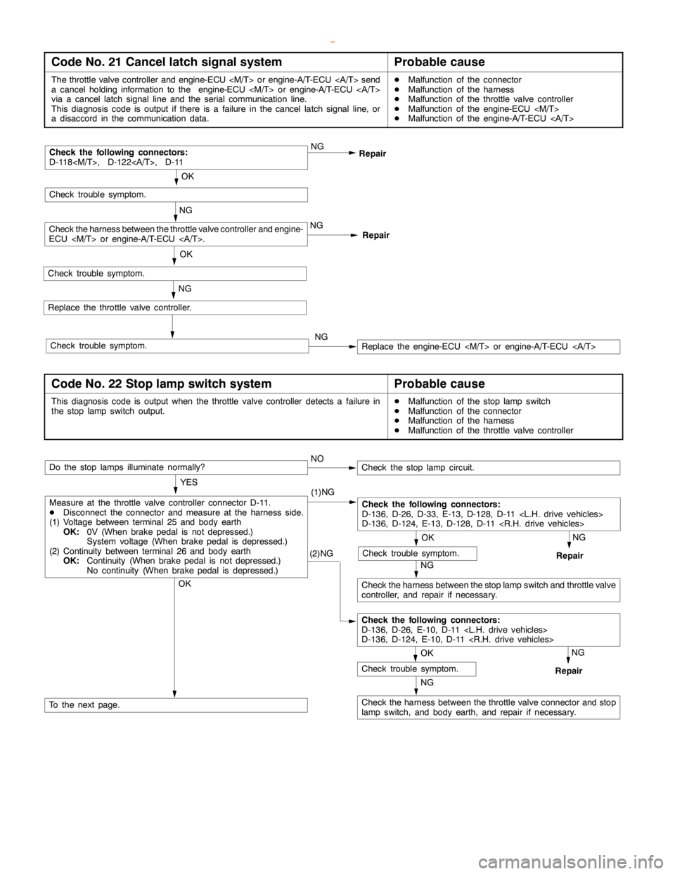
Code No. 21 Cancel latch signal systemProbable cause
The throttle valve controller and engine-ECU
a cancelholding information to the engine-ECU
via a cancel latch signal line and the serial communication line.
This diagnosis code is output if there is a failure in the cancel latch signal line, or
a disaccord in the communication data.DMalfunction of the connector
DMalfunction of the harness
DMalfunction of the throttle valve controller
DMalfunction of the engine-ECU
DMalfunction of the engine-A/T-ECU
Repair NG
RepairCheck the following connectors:
D-118
OK
Replace the throttle valve controller.
NG
NG
Check the harness between the throttle valve controller and engine-
ECU
Replace the engine-ECU
Check trouble symptom.
OK
Check trouble symptom.
Check trouble symptom.NG
Code No. 22 Stop lamp switch systemProbable cause
This diagnosis code is output when the throttle valve controller detects a failure in
the stoplampswitch output.DMalfunction of the stoplampswitch
DMalfunction of the connector
DMalfunction of the harness
DMalfunction of the throttle valve controller
(2)NG
NG
Check the harness between the throttle valve connector and stop
lampswitch, and body earth, and repair if necessary.
NG
Repair
OK
Check trouble symptom.
Measure at the throttle valve controller connector D-11.
DDisconnect the connector and measure at the harness side.
(1) Voltage between terminal 25 and body earth
OK:0V (When brakepedal is not depressed.)
System voltage (When brakepedal is depressed.)
(2) Continuity between terminal 26 and body earth
OK:Continuity (When brakepedal is not depressed.)
No continuity (When brakepedal is depressed.)NO
Do the stop lamps illuminate normally?
OK
To the next page.
Check the following connectors:
D-136, D-26, D-33, E-13, D-128, D-11
D-136, D-124, E-13, D-128, D-11
OK
Check trouble symptom.
NG
Check the harness between the stoplampswitch and throttle valve
controller, and repair if necessary.NG
Repair
Check the stoplampcircuit.
YES
(1)NG
Check the following connectors:
D-136, D-26, E-10, D-11
D-136, D-124, E-10, D-11
www.WorkshopManuals.co.uk
Purchased from www.WorkshopManuals.co.uk