2000 MITSUBISHI MONTERO low oil pressure
[x] Cancel search: low oil pressurePage 154 of 1839

ENGINE <4M4> -On-vehicle Service11C-13
8. If there is a cylinder which compression or compression
difference is outside the limit, pour a small amount of
engine oil through the glow plug hole, and repeat the
operations in steps 6 - 7.
(1) If the compression increases after the oil is added,
the cause of the malfunction is a worn or damaged
piston ring and /or cylinder inner surface.
(2) If the compression does not rise after the oil is added,
the cause is a burnt or defective valve seat, or pressure
is leaking from the gasket.
9. Connect the fuel cut solenoid valve connector.
10. Install the glow plugs.
www.WorkshopManuals.co.uk
Purchased from www.WorkshopManuals.co.uk
Page 217 of 1839

GDI -General Information13A-3
GENERAL INFORMATION
The Gasoline Direct Injection System consists
of sensors which detect the engine conditions,
the engine-ECU
which controls the system based on
signals from these sensors, and actuators
which operate under the control of the
engine-ECU
carries out activities such as fuel injection
control, idle speed control and ignition timing
control. In addition, the engine-ECU
engine-A/T-ECU is equipped with several
diagnosis modes which simplify troubleshooting
when a problem develops.
FUEL INJECTION CONTROL
The injector drive times and injector timing are
controlled so that the optimum air/fuel mixture
is supplied to the engine to correspond to the
continually-changing engine operation condi-
tions.
A single injector for each cylinder is mounted
at the cylinder head. The fuel is sent under
pressure from the fuel tank to the fuel pressure
regulator (low pressure) by the fuel pump (low
pressure). The pressure is regulated by the
fuel pressure regulator (low pressure) and the
fuel regulated is then sent to the fuel pump
(high pressure). The fuel under increased
pressure generated by the fuel pump (high
pressure) is then regulated by the fuel pressure
regulator (high pressure) and is then distributed
to each of the injectors via the delivery pipes.Fuel injection is normally carried out once for
each cylinder for every two rotations of the
crankshaft. The firing order is 1-2-3-4-5-6. This
is called sequential fuel injection.
When the engine is cold or under a severe
load, the “open-loop” control keeps the air/fuel
ratio at a richer than usual level to maintain
driveability. When the engine is under low or
medium loads, the air/fuel ratio becomes leaner
to reduce fuel consumption. When the engine
is running at medium or high loads after having
warmed up, the “closed-loop” control uses the
signal from the oxygen sensor to keep the
air/fuel ratio at the optimum theoretical level.
THROTTLE VALVE OPENING ANGLE CONTROL
This system controls throttle valve opening
angle electronically. The engine-ECU
or engine-A/T-ECU determines how
deeply the accelerator pedal is depressed by
means of the accelerator position sensor (APS).
Then the engine-ECU
throttle valve opening angle to the throttle valve
controller. The throttle valve control servo
operates the throttle valve so that it reaches
the target opening angle.
IDLE SPEED CONTROL
This system maintains engine idle speed at
a predetermined condition by controlling the
air flow that passes through the throttle valve
according to engine idling condition and engine
loads at idling.
The engine-ECU
operates the throttle valve control servoso that engine speed is maintained within a
map value. The map value is predetermined
according to engine coolant temperature and
air-conditioning load.
IGNITION TIMING CONTROL
The power transistor located in the ignition
primary circuit turns ON and OFF to control
the primary current flow to the ignition coil. This
controls the ignition timing in order to provide
the optimum ignition timing with respect to the
engine operating conditions. The ignition timingis determined by the engine-ECU
engine-A/T-ECU from the engine speed,
intake air volume, engine coolant temperature,
atmospheric pressure and injection timing
(intake stroke or compression stroke).
www.WorkshopManuals.co.uk
Purchased from www.WorkshopManuals.co.uk
Page 227 of 1839

GDI -Troubleshooting
FAIL-SAFE FUNCTION REFERENCE TABLE
When the main sensor malfunctions are detected by the diagnosis function, the vehicle is controlled
by means of the pre-set control logic to maintain safe conditions for driving.
Malfunctioning itemControl contents during malfunction
Air flow sensor1. Suspends lean burn operation.
2. Uses the throttle position sensor signal and engine speed signal (crank angle
sensor signal) to take reading of the basic injector drive time and basic ignition
timing from the pre-set mapping.
Intake air temperature sensorControls as if the intake air temperature is 25_
C.
Throttle position sensor (2nd
channel)1. Suspends lean burn operation.
2. Controls the throttle opening angle feedback (half as much as the opening
rate in the normal condition) by using signals from the throttle position sensor
(1st channel). However, this controlling system is not applied if the throttle
position sensor (1st channel) and throttle position sensor (2nd channel)
combination output voltage is outside 4 - 6 V.
3. Refrains from controlling the throttle opening angle feedback if the throttle
position sensor (1st channel) is also defective.
Engine coolant temperature
sensorControls as if the engine coolant temperature is 80_
C. (Moreover, the control system
is working until the ignition switch is turned OFF if the sensor signal returns to normal.)
Camshaft position sensorCuts the fuel supply once a malfunction is detected. (Only when there has been
no occasion of detecting No.1 cylinder top dead centre after the ignition switch
is turned ON.)
Vehicle speed sensor1. Suspends lean burn operation. However, the control is cancelled as a certain
time passes by with the engine speed of 1,500 r/min or more.
2. Suspends lean burn operation during the engine idling.
Barometric pressure sensorControls as if the barometric pressure is 101 kPa.
Detonation sensorFixes the ignition timing as that for standard petrol.
Injector1. Suspends lean burn operation.
2. Suspends the exhaust gas recirculation.
Ignition coil (incorporating pow-
er transistor)1. Suspends lean burn operation.
2. Cuts off the fuel supply to cylinders with an abnormal ignition signal.
Fuel pressure sensor1. Controls as if the fuel pressure is 5MPa.
2
. Suspends fuel injection. (when the low pressure is detected and the engine
speed is more than 3,000r/min)
Alternator FR terminalRefrains from controlling to suppress the alternator output to electrical load.
(Operated as a normal alternator)
Accelerator pedal position sen-
sor (2nd channel)1. Suspends lean burn operation.
2. Controls the throttle valve position by using signals from the accelerator pedal
position sensor (1st channel). (However, the control system is not applicable
if the difference from the accelerator pedal position sensor (1st channel) output
voltage is 1.0 V or higher.)
3
. Suspends the electronic controlled throttle valve system if accelerator pedal
position sensor (1st channel) is also defective.
www.WorkshopManuals.co.uk
Purchased from www.WorkshopManuals.co.uk
Page 229 of 1839

GDI -Troubleshooting
INSPECTION CHART FOR DIAGNOSIS CODES
Code No.Diagnosis itemReference page
P0100Air flow sensor system13A-17
P0105Barometric pressure sensor system13A-19
P0110Intake air temperature sensor system13A-21
P0115Engine coolant temperature sensor system13A-22
P0120LThrottle position sensor (1st channel) system13A-25
P0125Feedback system13A-27
P0130Oxygen sensor (front) system
P0135Oxygen sensor heater (front) system
P0136Oxygen sensor (rear) system
P0141Oxygen sensor heater (rear) system
P0170Abnormal fuel system13A-34
P0190LAbnormal fuel pressure13A-36
P0201No.1 injector system13A-38
P0202No.2 injector system13A-40
P0203No.3 injector system13A-42
P0204No.4 injector system13A-44
P0205No.5 injector system13A-46
P0206No.6 injector system13A-48
P0220LAccelerator pedal position sensor (1st channel) system13A-50
P0225LThrottle position sensor (2nd channel) system13A-52
P0300LIgnition coil (power transistor) system13A-53
P0301No.1 cylinder misfire detected.13A-55
P0302No.2 cylinder misfire detected.13A-55
P0303No.3 cylinder misfire detected.13A-55
P0304No.4 cylinder misfire detected.13A-55
P0305No.5 cylinder misfire detected.13A-55
P0306No.6 cylinder misfire detected.13A-55
P0325Detonation sensor system13A-56
P0335Crank angle sensor system13A-56
P0340Camshaft position sensor system13A-58
P0403EGR valve system13A-60
P0420Catalyst malfunction13A-61
www.WorkshopManuals.co.uk
Purchased from www.WorkshopManuals.co.uk
Page 269 of 1839

GDI -Troubleshooting
Code No.P0301 No.1 cylinder misfire detected.
Code No.P0302 No.2 cylinder misfire detected.
Code No.P0303 No.3 cylinder misfire detected.
Code No.P0304 No.4 cylinder misfire detected.
Code No.P0305 No.5 cylinder misfire detected.Probable cause
Range of Check
DThe enginespeed is 500 - 4,500 r/min.
DWhile the engine is runningexcept deceleration and sudden acceleration.
Set Conditions
DThe number of misfires exceeds a predetermined number per 200engine
revolutions (Misfire has occurred in only one cylinder).
or
DThe number of misfires exceeds a predetermined number per 100engine
revolutions (Misfire has occurred in only one cylinder).DMalfunction of the ignition system
DAbnormal compression
DMalfunction of injector
DMalfunction of engine-ECU
NG
Check the harness wire between the
ignition coil and the engine-ECU.
NG
Replace
NG
Repair
(2) NG
OK
Check the ignition failure sensor
(Refer to GROUP 16 - Ignition
System.)
OK
Check the harness wire between the
ignition coil and the earth, and repair
if necessary. (3) NG
OK
Measure at ignition coil connectors
B-101, B-108, B-112, B-113, B-116,
B-119.
DDisconnect the connector and
measure at the harness side.
(1) The voltage between terminal 1
and earth
(Ignition switch: ON)
OK:
System voltage
(2) The voltage between terminal 3
and earth
(Engine: cranking)
OK:
0.5 - 4.0 V
(3) The resistance between terminal
2 and earth
OK:
2Wor less(1) NGCheck the following connectors:
B-04, B-107, D-208, D-223NG
Repair
Check the ignition coil (Refer to
GROUP 16 - Ignition System.)
Check the compression pressure.
(Refer to GROUP 11A - On-vehicle
Service.)Repair
Replace the engine-ECU.
OK
Check the harness wire between the
ignition coil and the ignition failure
sensor, and between the ignition coil
and the ignition failure sensor.
NG
Repair
OK
NGNG
Repair
OKReplace
NG
Check the spark plugs.
Check the trouble symptoms.
OK
Check the trouble symptoms.NGReplace the engine-ECU.
Check the following connectors:
B-101, B-108, B-112, B-113, B-116,
B-119
Check the following connector:
B-107, D-116
OK
www.WorkshopManuals.co.uk
Purchased from www.WorkshopManuals.co.uk
Page 291 of 1839

GDI -Troubleshooting
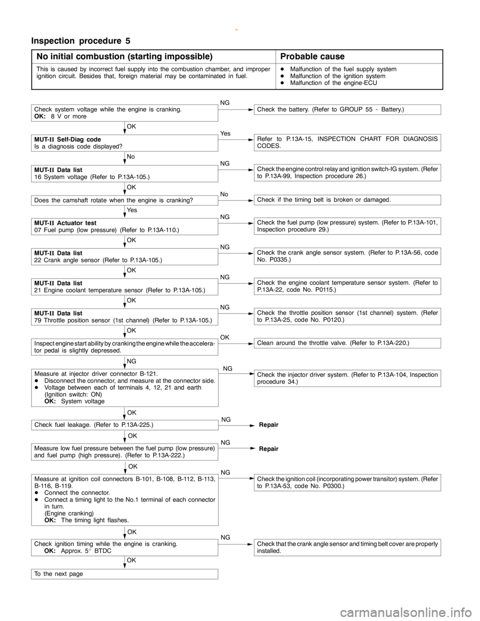
Inspection procedure 5
No initial combustion (starting impossible)
Probable cause
This is caused by incorrect fuel supply into the combustion chamber, and improper
ignition circuit. Besides that, foreign material may be contaminated in fuel.DMalfunction of the fuel supply system
DMalfunction of the ignition system
DMalfunction of the engine-ECU
Check system voltage while theengine iscranking.
OK:
8 V or moreNGCheck the battery. (Refer to GROUP 55 - Battery.)
OK
MUT-
IISelf-Diag code
Is a diagnosis code displayed?Ye sRefer to P.13A-15, INSPECTION CHART FOR DIAGNOSIS
CODES.
No
MUT-
IIData list
16 System voltage (Refer to P.13A-105.)NGCheck theengine controlrelay and ignition switch-IG system. (Refer
to P.13A-99, Inspection procedure 26.)
OK
Does the camshaft rotate when theengine is cranking?NoCheck if thetiming belt isbroken ordamaged.
Ye s
MUT-
IIActuator test
07 Fuel pump(low pressure) (Refer to P.13A-110.)NGCheck the fuelpump(low pressure) system. (Refer to P.13A-101,
Inspection procedure 29.)
OK
MUT-
IIData list
22 Crankanglesensor (Refer to P.13A-105.)NGCheck the crankanglesensor system. (Refer to P.13A-56, code
No. P0335.)
OK
MUT-
IIData list
21 Engine coolant temperature sensor (Refer to P.13A-105.)NGCheck theengine coolant temperaturesensor system. (Refer to
P.13A-22, code No. P0115.)
OK
MUT-
IIData list
79 Throttle position sensor (1st channel) (Refer to P.13A-105.)NGCheck the throttle position sensor (1st channel) system. (Refer
to P.13A-25, code No. P0120.)
OK
Inspectenginestart ability by cranking theengine while theaccelera-
tor pedal isslightly depressed.OKClean around the throttle valve. (Refer to P.13A-220.)
NG
Check fuel leakage. (Refer to P.13A-225.)NG
Repair
OK
Measure low fuel pressure between the fuelpump(low pressure)
and fuel pump (highpressure). (Refer to P.13A-222.)NG
Repair
OK
Measure at ignition coil connectors B-101, B-108, B-112, B-113,
B-116, B-119.
DConnect the connector.
DConnect atiming light to theNo.1 terminal of each connector
in turn.
(Engine cranking)
OK:
The timing lightflashes.NGCheck the ignition coil (incorporating power transitor) system. (Refer
to P.13A-53, code No. P0300.)
OK
Check ignitiontiming while the engine iscranking.
OK:
Approx. 5_BTDCNGCheck that the crankanglesensor andtiming beltcover are properly
installed.
OK
To the nextpage
Measure at injector driver connector B-121.
DDisconnect the connector, and measure at the connector side.
DVoltage between each of terminals 4, 12, 21 and earth
(Ignition switch: ON)
OK:
System voltageCheck the injector driver system. (Refer to P.13A-104, Inspection
procedure 34.) NG
OK
www.WorkshopManuals.co.uk
Purchased from www.WorkshopManuals.co.uk
Page 292 of 1839

GDI -Troubleshooting
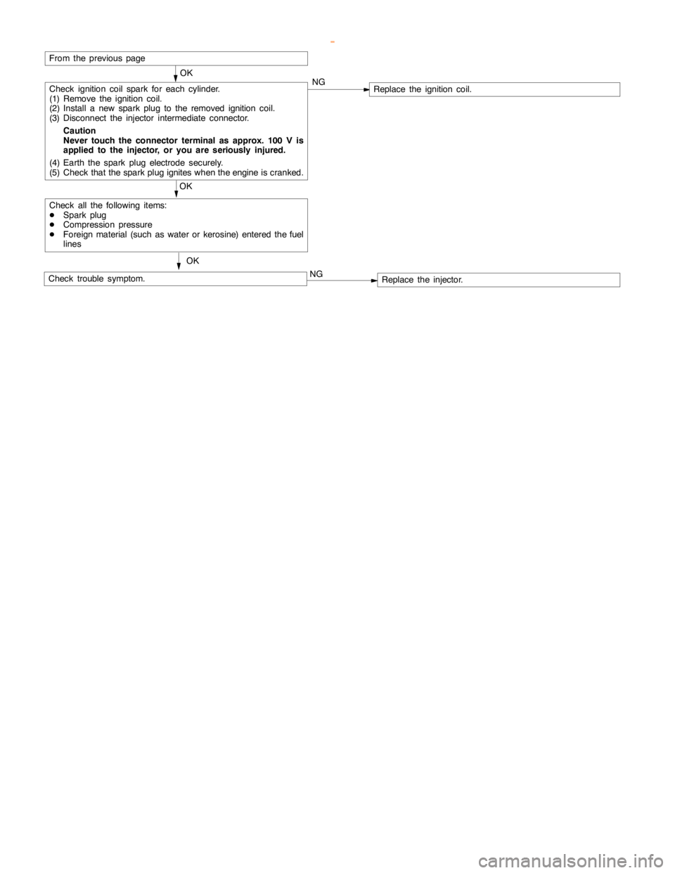
OK
Check ignition coil spark for each cylinder.
(1) Remove the ignition coil.
(2) Install a new sparkplug to the removed ignitioncoil.
(3) Disconnect the injector intermediate connector.
Caution
Never touch the connector terminal as approx. 100 V is
applied to the injector, or you are seriously injured.
(4) Earth the sparkplug electrodesecurely.
(5) Check that the sparkplug igniteswhen theengine iscranked.NGReplace the ignition coil.
OK
Check all the following items:
DSparkplug
DCompression pressure
DForeign material (such as water or kerosine) entered the fuel
lines
Check trouble symptom.OKNGReplace the injector.
From the previouspage
www.WorkshopManuals.co.uk
Purchased from www.WorkshopManuals.co.uk
Page 294 of 1839

GDI -Troubleshooting
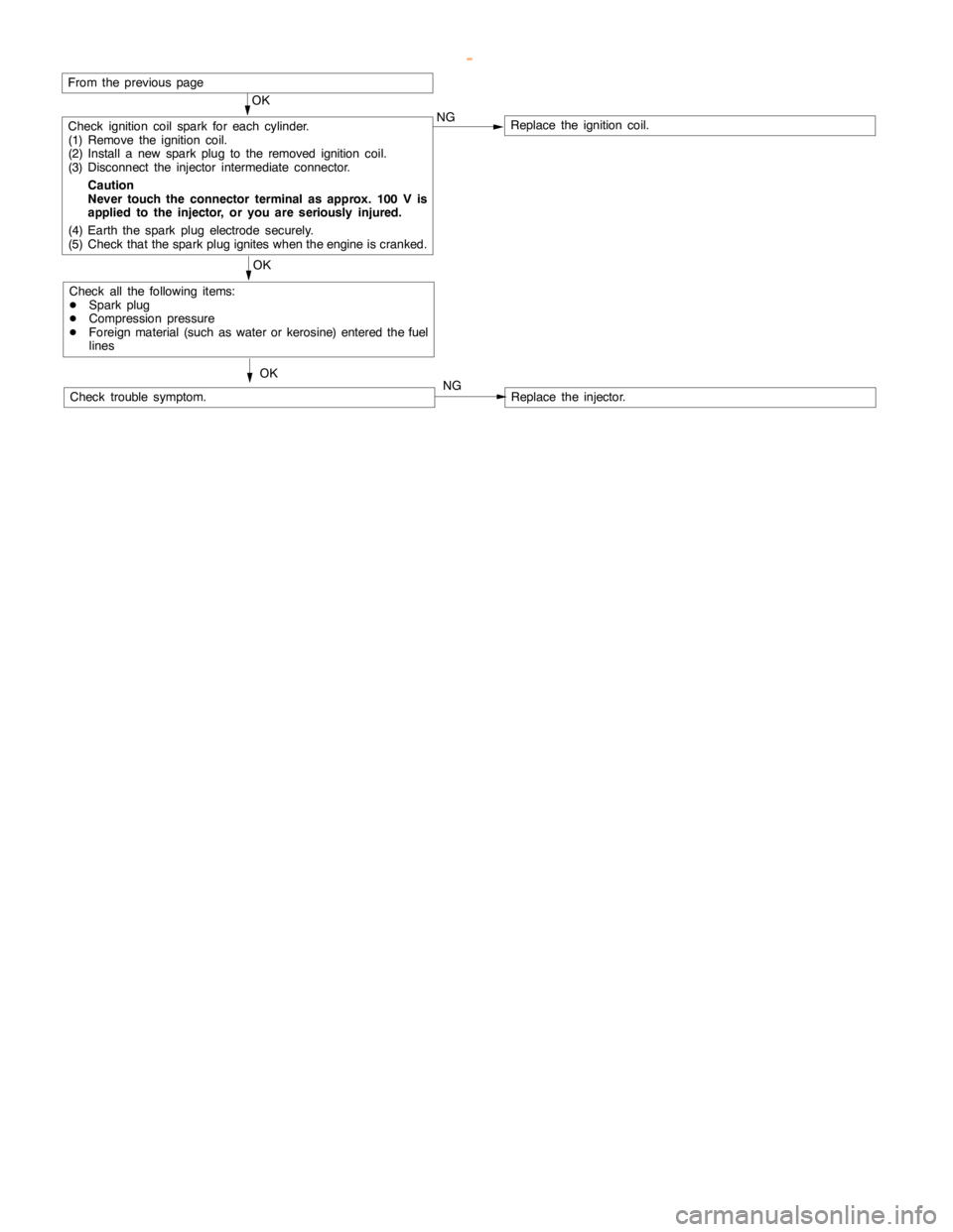
OK
Check ignition coil spark for each cylinder.
(1) Remove the ignition coil.
(2) Install a new sparkplug to the removed ignitioncoil.
(3) Disconnect the injector intermediate connector.
Caution
Never touch the connector terminal as approx. 100 V is
applied to the injector, or you are seriously injured.
(4) Earth the sparkplug electrodesecurely.
(5) Check that the sparkplug igniteswhen theengine iscranked.NGReplace the ignition coil.
OK
Check all the following items:
DSparkplug
DCompression pressure
DForeign material (such as water or kerosine) entered the fuel
lines
Check trouble symptom.OKNGReplace the injector.
From the previouspage
www.WorkshopManuals.co.uk
Purchased from www.WorkshopManuals.co.uk