2000 MITSUBISHI MONTERO relay
[x] Cancel search: relayPage 216 of 1839

13A-2
GASOLINE DIRECT
INJECTION (GDI)
CONTENTS
GENERAL INFORMATION 3..................
SERVICE SPECIFICATIONS 7.................
SEALANT 7..................................
SPECIAL TOOLS 7..........................
TROUBLESHOOTING
TROUBLESHOOTING 126.............
ON-VEHICLE SERVICE 219..................
Fuel Pump Connector Disconnection (How to
Reduce the Fuel Pressure) 219.................
Fuel Pump Operation (Low Pressure) Check 220.
Throttle Body (Throttle Valve Area) Cleaning 220.
Throttle Position Sensor Adjustment 220.........
Accelerator Pedal Position Sensor
Adjustment 221................................
Fuel Pressure Test 222.........................
Fuel Leak Check 225...........................
Component Location 226........................
Engine Control Relay, Fuel Pump Relay, Injector
Driver Control Relay and Throttle Valve Control
Servo Relay Continuity Check 227...............Intake Air Temperature Sensor Check 227.......
Engine Coolant Temperature Sensor Check 227..
Throttle Position Sensor Check 228..............
Accelerator Pedal Position Sensor Check 229....
Accelerator Pedal Position Switch Check 230.....
Oxygen Sensor Check 230......................
Injector Check 232.............................
Throttle Valve Control Servo Check 232..........
Clutch Switch Check 233.......................
Purge Control Solenoid Valve Check 233.........
EGR Valve Check 233..........................
INJECTOR 234.............................
FUEL PUMP (HIGH PRESSURE) 239.........
THROTTLE BODY 242.......................
INJECTOR DRIVER 245.....................
ENGINE-ECU, ENGINE-A/T-ECU ,
THROTTLE VALVE CONTROLLER 246.......
www.WorkshopManuals.co.uk
Purchased from www.WorkshopManuals.co.uk
Page 218 of 1839

GDI -General Information13A-4
SELF-DIAGNOSIS FUNCTION
DWhen an abnormality is detected in one
of the sensors or actuators related to
emission control, the engine warning lamp
(check engine lamp) illuminates or flashes
as a warning to the driver.
DWhen an abnormality is detected in one
of the sensors or actuators, a diagnosis
code corresponding to the abnormality is
output.
DThe engine-ECU records the engine
operating condition when the diagnosis
code is set. This data is called “freezeframe” data.
This data can be read by using the MUT-II,
and can then be used in simulation tests
for troubleshooting.
DThe RAM data inside the engine-ECU
related to the sensors and actuators can
be read by means of the MUT-II. In addition,
the actuators can be force-driven under
certain circumstances.
OTHER CONTROL FUNCTIONS
1. Fuel Pump Control
Turns the fuel pump relay ON so that current
is supplied to the fuel pump while the engine
is cranking or running.
2. A/C Relay Control
Turns the compressor clutch of the A/C
ON and OFF.3. Purge Control Solenoid Valve Control
Refer to GROUP 17.
4. EGR Control Servo Control
Refer to GROUP 17.
GENERAL SPECIFICATIONS
ItemsSpecifications
Throttle bodyThrottle bore mm65
Throttle position sensorVariable resistor type
Throttle valve control servoBrushless DC-motor type
Engine-ECUIdentification model No.E2T79271
E2T79272
Engine-Identification model No.E2T76277
A/T-ECU
E2T76278
www.WorkshopManuals.co.uk
Purchased from www.WorkshopManuals.co.uk
Page 219 of 1839

GDI -General Information13A-5
Items Specifications
SensorsAir flow sensorKarman vortex type
Barometric pressure sensorSemiconductor type
Intake air temperature sensorThermistor type
Engine coolant temperature sensorThermistor type
Oxygen sensorZirconia type
Accelerator pedal position sensor (1st
and 2nd channels)Variable resistor type
Accelerator pedal position switchRotary contact type, within accelerator pedal position
sensor (1st channel)
Vehicle speed sensorMagnetic resistive element type
Inhibitor switchContact switch type
Camshaft position sensorHall element type
Crank angle sensorHall element type
Detonation sensorPiezoelectric type
Fuel pressure sensorMetallic membrane type
Power steering fluid pressure switchContact switch type
ActuatorsEngine control relay typeContact switch type
Fuel pump relay typeContact switch type
Injector driver control relayContact switch type
Injector type and numberElectromagnetic type, 6
Injector identification markDIM 1070
Throttle valve control servo relayContact switch type
Throttle valve control servoBrushless DC-motor type
EGR valveStepper motor type
Purge control solenoid valveDuty cycle type solenoid valve
Fuel pressure
regulator (low
pressure)Regulator pressure kPa329
Fuel pressure
regulator
(high pres-
sure)Regulator pressure MPa5.0
www.WorkshopManuals.co.uk
Purchased from www.WorkshopManuals.co.uk
Page 231 of 1839
GDI -Troubleshooting
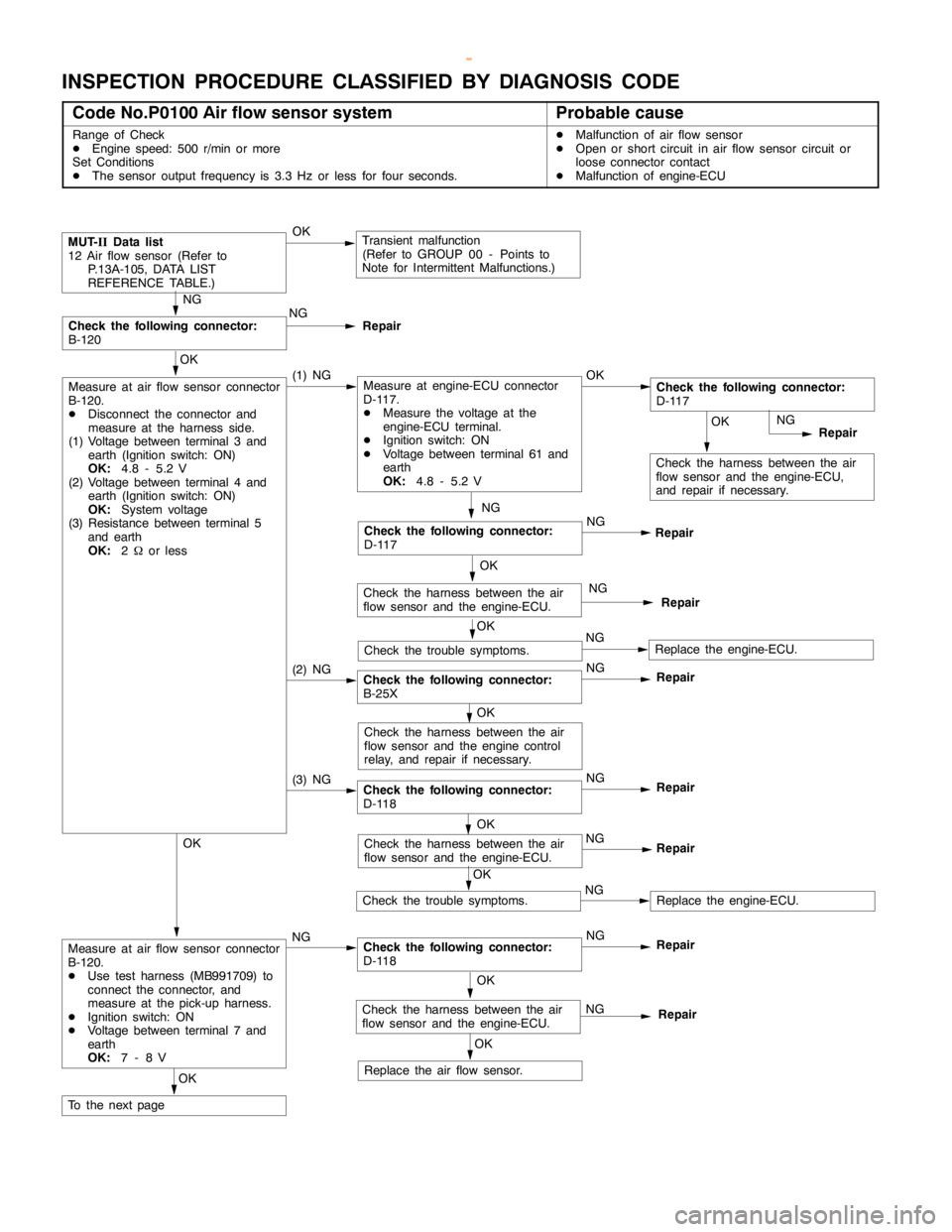
INSPECTION PROCEDURE CLASSIFIED BY DIAGNOSIS CODE
Code No.P0100 Air flow sensor systemProbable cause
Range of Check
DEngine speed: 500 r/min or more
Set Conditions
DThe sensor output frequency is 3.3 Hz or less for four seconds.DMalfunction of air flow sensor
DOpen or short circuit in air flow sensor circuit or
loose connector contact
DMalfunction of engine-ECU
(3) NGCheck the following connector:
D-118NG
Repair
(2) NGCheck the following connector:
B-25XNG
Repair
OK
Check the harness between the air
flow sensor and the engine-ECU,
and repair if necessary.
MUT-
IIData list
12 Air flow sensor (Refer to
P.13A-105, DATA LIST
REFERENCE TABLE.)OKTransient malfunction
(Refer to GROUP 00 - Points to
Note for Intermittent Malfunctions.)
NG
Check the following connector:
B-120NG
Repair
OK
Measure at air flow sensor connector
B-120.
DDisconnect the connector and
measure at the harness side.
(1) Voltage between terminal 3 and
earth (Ignition switch: ON)
OK:
4.8 - 5.2 V
(2) Voltage between terminal 4 and
earth (Ignition switch: ON)
OK:
System voltage
(3) Resistance between terminal 5
and earth
OK:
2Wor less(1) NGMeasure at engine-ECU connector
D-117.
DMeasure the voltage at the
engine-ECU terminal.
DIgnition switch: ON
DVoltage between terminal 61 and
earth
OK:
4.8 - 5.2 VOKCheck the following connector:
D-117
NG
Repair
OK
Replace the air flow sensor.
NG
Check the following connector:
D-117NG
Repair
OK
Check the harness between the air
flow sensor and the engine-ECU.NG
Repair
OK
Check the trouble symptoms.NGReplace the engine-ECU.
OK
Check the harness between the air
flow sensor and theengine control
relay, and repair if necessary.
OK
Check the harness between the air
flow sensor and the engine-ECU.NG
Repair
OK
Check the trouble symptoms.NGReplace the engine-ECU.
OK
Measure at air flow sensor connector
B-120.
DUse test harness (MB991709) to
connect the connector, and
measure at the pick-up harness.
DIgnition switch: ON
DVoltage between terminal 7 and
earth
OK:
7-8VNGCheck the following connector:
D-118NG
Repair
OK
Check the harness between the air
flow sensor and the engine-ECU.NG
Repair
OK
To the nextpage
www.WorkshopManuals.co.uk
Purchased from www.WorkshopManuals.co.uk
Page 232 of 1839
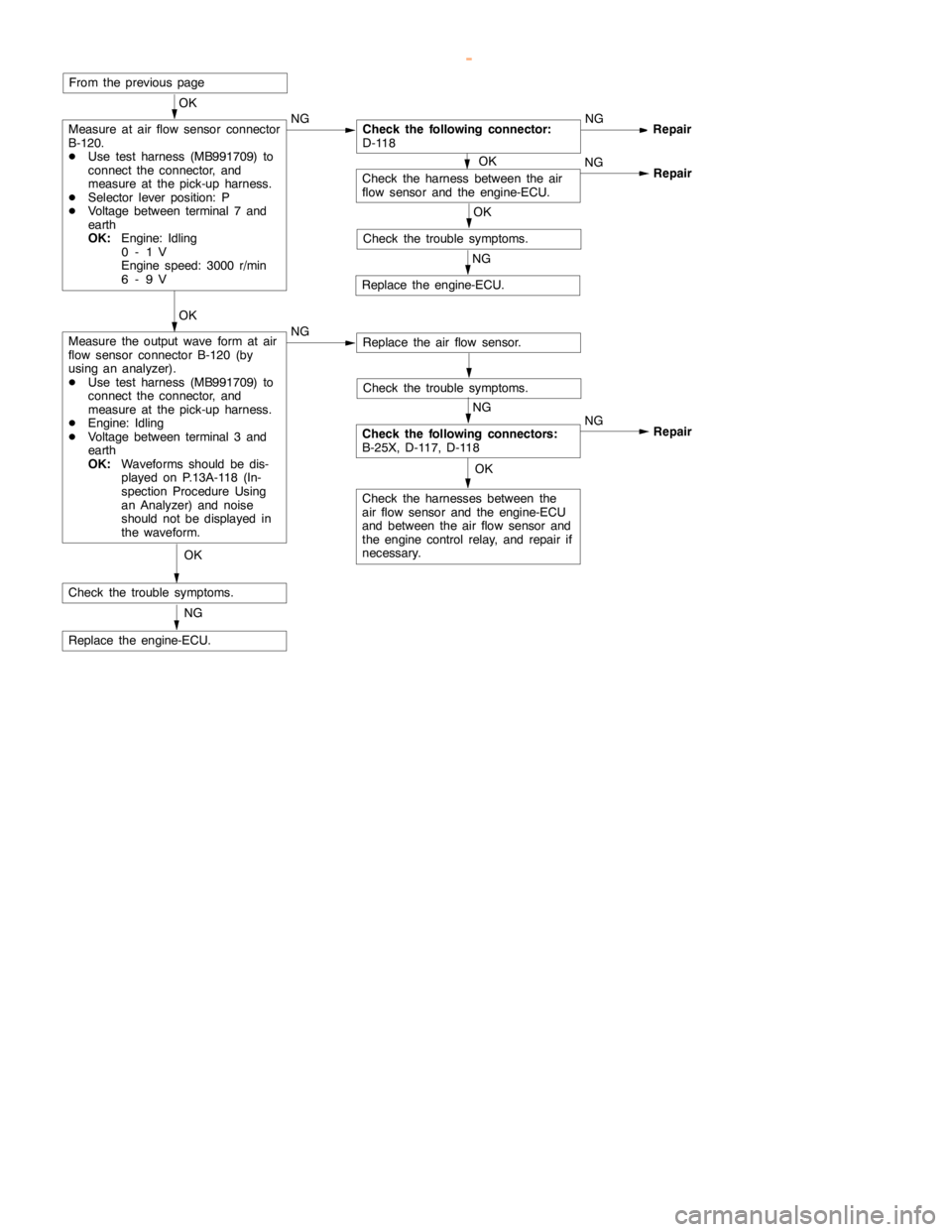
GDI -Troubleshooting
OK
Check the harness between the air
flow sensor and the engine-ECU.NG
Repair
OK
Check the harnesses between the
air flow sensor and the engine-ECU
and between the air flow sensor and
the engine controlrelay, and repair if
necessary.
From the previouspage
OK
Measure at air flow sensor connector
B-120.
DUse test harness (MB991709) to
connect the connector, and
measure at the pick-up harness.
DSelector lever position: P
DVoltage between terminal 7 and
earth
OK:
Engine: Idling
0-1V
Engine speed: 3000 r/min
6-9VNGCheck the following connector:
D-118NGRepair
OK
Check the trouble symptoms.
NG
Replace the engine-ECU.
Check the trouble symptoms.
NG
Check the following connectors:
B-25X, D-117, D-118NG
Repair
OK
Measure the output wave form at air
flow sensor connector B-120 (by
using an analyzer).
DUse test harness (MB991709) to
connect the connector, and
measure at the pick-up harness.
DEngine: Idling
DVoltage between terminal 3 and
earth
OK:
Waveforms should be dis-
played on P.13A-118 (In-
spection Procedure Using
an Analyzer) and noise
should not be displayed in
the waveform.NGReplace the air flow sensor.
OK
Check the trouble symptoms.
NG
Replace the engine-ECU.OK
www.WorkshopManuals.co.uk
Purchased from www.WorkshopManuals.co.uk
Page 244 of 1839
GDI -Troubleshooting
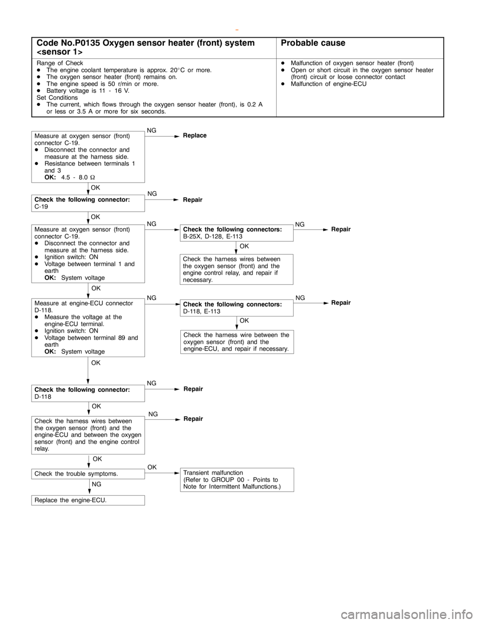
Code No.P0135 Oxygen sensor heater (front) system
Range of Check
DThe engine coolant temperature is approx. 20_C or more.
DThe oxygen sensor heater (front) remains on.
DThe enginespeed is 50 r/min or more.
DBattery voltage is 11 - 16 V.
Set Conditions
DThe current, which flows through the oxygen sensor heater (front), is 0.2 A
or less or 3.5 A or more for six seconds.DMalfunction of oxygen sensor heater (front)
DOpen or short circuit in the oxygen sensor heater
(front) circuit or loose connector contact
DMalfunction of engine-ECU
OK
Check the harness wire between the
oxygen sensor (front) and the
engine-ECU, and repair if necessary.
Repair
OK
Measure at engine-ECU connector
D-118.
DMeasure the voltage at the
engine-ECU terminal.
DIgnition switch: ON
DVoltage between terminal 89 and
earth
OK:
System voltageNGCheck the following connectors:
D-118, E-113NG
OK
Check the harness wires between
the oxygen sensor (front) and the
engine controlrelay, and repair if
necessary.
Measure at oxygen sensor (front)
connector C-19.
DDisconnect the connector and
measure at the harness side.
DResistance between terminals 1
and 3
OK:
4.5 - 8.0WNG
Replace
Repair
OK
Measure at oxygen sensor (front)
connector C-19.
DDisconnect the connector and
measure at the harness side.
DIgnition switch: ON
DVoltage between terminal 1 and
earth
OK:
System voltageNGCheck the following connectors:
B-25X, D-128, E-113NG
OK
Check the following connector:
C-19NG
Repair
OK
Check the trouble symptoms.OKTransient malfunction
(Refer to GROUP 00 - Points to
Note for Intermittent Malfunctions.) NG
Replace the engine-ECU.
OK
Check the following connector:
D-118NG
Repair
OK
Check the harness wires between
the oxygen sensor (front) and the
engine-ECU and between the oxygen
sensor (front) and theengine control
relay.NG
Repair
www.WorkshopManuals.co.uk
Purchased from www.WorkshopManuals.co.uk
Page 247 of 1839
GDI -Troubleshooting
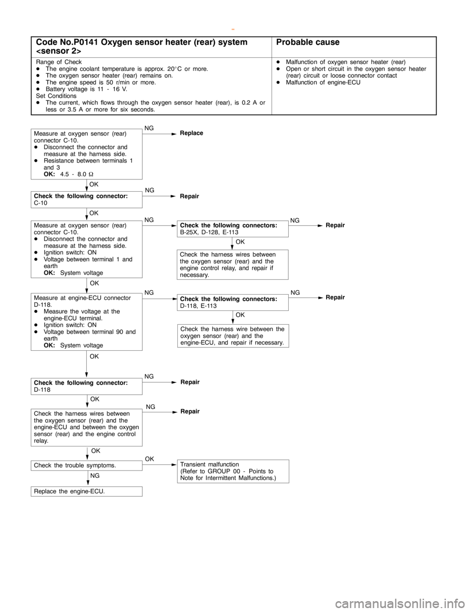
Code No.P0141 Oxygen sensor heater (rear) system
Range of Check
DThe engine coolant temperature is approx. 20_C or more.
DThe oxygen sensor heater (rear) remains on.
DThe enginespeed is 50 r/min or more.
DBattery voltage is 11 - 16 V.
Set Conditions
DThe current, which flows through the oxygen sensor heater (rear), is 0.2 A or
less or 3.5 A or more for six seconds.DMalfunction of oxygen sensor heater (rear)
DOpen or short circuit in the oxygen sensor heater
(rear) circuit or loose connector contact
DMalfunction of engine-ECU
OK
Check the harness wire between the
oxygen sensor (rear) and the
engine-ECU, and repair if necessary.
Repair
OK
Measure at engine-ECU connector
D-118.
DMeasure the voltage at the
engine-ECU terminal.
DIgnition switch: ON
DVoltage between terminal 90 and
earth
OK:
System voltageNGCheck the following connectors:
D-118, E-113NG
OK
Check the harness wires between
the oxygen sensor (rear) and the
engine controlrelay, and repair if
necessary.
Measure at oxygen sensor (rear)
connector C-10.
DDisconnect the connector and
measure at the harness side.
DResistance between terminals 1
and 3
OK:
4.5 - 8.0WNG
Replace
Repair
OK
Measure at oxygen sensor (rear)
connector C-10.
DDisconnect the connector and
measure at the harness side.
DIgnition switch: ON
DVoltage between terminal 1 and
earth
OK:
System voltageNGCheck the following connectors:
B-25X, D-128, E-113NG
OK
Check the following connector:
C-10NG
Repair
OK
Check the trouble symptoms.OKTransient malfunction
(Refer to GROUP 00 - Points to
Note for Intermittent Malfunctions.) NG
Replace the engine-ECU.
OK
Check the following connector:
D-118NG
Repair
OK
Check the harness wires between
the oxygen sensor (rear) and the
engine-ECU and between the oxygen
sensor (rear) and theengine control
relay.NG
Repair
www.WorkshopManuals.co.uk
Purchased from www.WorkshopManuals.co.uk
Page 271 of 1839
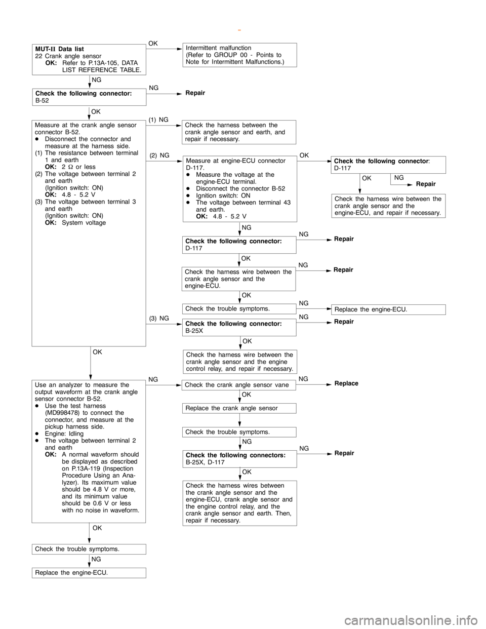
GDI -Troubleshooting
OK
Check the harness wire between the
crankanglesensor and the
engine-ECU, and repair if necessary.
MUT-
IIData list
22 Crankanglesensor
OK:
Refer to P.13A-105, DATA
LIST REFERENCE TABLE.OKIntermittent malfunction
(Refer to GROUP 00 - Points to
Note for Intermittent Malfunctions.)
OK
Measure at the crankanglesensor
connector B-52.
DDisconnect the connector and
measure at the harness side.
(1) The resistance between terminal
1 and earth
OK:
2Wor less
(2) The voltage between terminal 2
and earth
(Ignition switch: ON)
OK:
4.8 - 5.2 V
(3) The voltage between terminal 3
and earth
(Ignition switch: ON)
OK:
System voltage(1) NGCheck the harness between the
crankanglesensor and earth, and
repair if necessary.
NG
Repair
NG
Check the following connector:
D-117NG
Repair
NG
Check the following connector:
B-52NG
Repair
(2) NGMeasure at engine-ECU connector
D-117.
DMeasure the voltage at the
engine-ECU terminal.
DDisconnect the connector B-52
DIgnition switch: ON
DThe voltage between terminal 43
and earth.
OK:
4.8 - 5.2 VOKCheck the following connector
:
D-117
Check the following connector:
B-25XNG
Repair
OK
Check the harness wire between the
crankanglesensor and the
engine-ECU.NG
Repair
OK
Check the trouble symptoms.NGReplace the engine-ECU.
(3) NG
OK
Check the harness wire between the
crankanglesensor and theengine
control relay, and repair if necessary.OK
Use an analyzer to measure the
output waveform at the crankangle
sensor connector B-52.
DUse the test harness
(MD998478) to connect the
connector, and measure at the
pickup harness side.
DEngine: Idling
DThe voltage between terminal 2
and earth
OK:
A normal waveform should
be displayed as described
on P.13A-119 (Inspection
Procedure Using an Ana-
lyzer). Its maximum value
should be 4.8 V or more,
and its minimumvalue
should be 0.6 V or less
with no noise in waveform.NGCheck the crankanglesensor vaneNG
Replace
OK
Replace the crankanglesensor
Check the trouble symptoms.
NG
Check the following connectors:
B-25X, D-117NG
Repair
OK
Check the harness wires between
the crankanglesensor and the
engine-ECU, crankanglesensor and
the engine controlrelay, and the
crankanglesensor and earth. Then,
repair if necessary.
OK
Check the trouble symptoms.
NG
Replace the engine-ECU.
www.WorkshopManuals.co.uk
Purchased from www.WorkshopManuals.co.uk