2000 MITSUBISHI MONTERO ABS
[x] Cancel search: ABSPage 122 of 1839

2
3
2 2
1
5
16 2
0
21
1 4 1
7
1
8
19
2
2
±4
N×m
2 2
±4
N×m
44
±5
N×m 1
2
±2
N×m
4 4
±1
0
N×m * 1
8
1
8
D Coolin g fa n
( R efe r to G
RO UP 14
.)
A A"
14. A lt e rn ato r and pow er ste erin g oil
p um p driv e belt
A B"
15. P ow er ste erin g oil pum p asse m bly
1 6. E ngin e oil co ole r hose s co nnectio n
1 7. Fuel hose s co nnectio ns
1 8. Vacu um hose s co nnectio n
1 9. B ra ke booste r va cu um hose
c o nnectio n
0. A cce le ra to r ca ble co nnectio n
2 1. H eate r hose s co nnectio n
< V ehic le s wit h A/C >
D Tra nsm is sio n asse m bly
( R efe r to G
RO UP 22
.)
2 2. E ngin e su pport fr o nt in su la to r
a tta ch in g bolt
A C"
"
AA
23. E ngin e asse m bly
w
ww.W ork sh opM an uals .c o .u k
P urc h ased f r o m w ww.W ork sh opM an uals .c o .u k
Page 157 of 1839
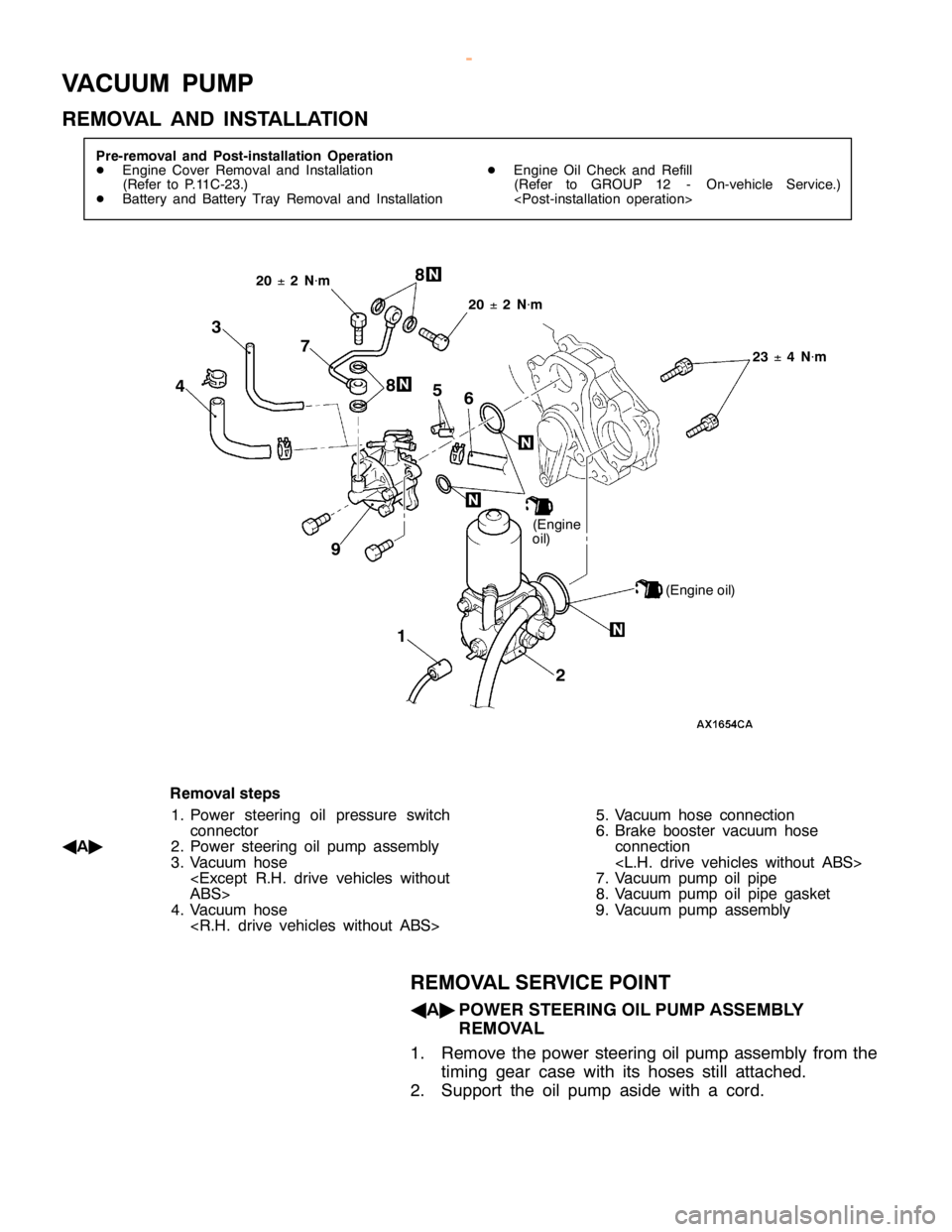
V
A CUUM PU M P
R EM OVA L AND IN STA LLA TIO N (
E ngin e
o il)
2 5
1 9
(E ngin e oil)
4
6
R em oval ste p s
1 . P ow er ste erin g oil pre ssu re sw it c h
c o nnecto r
A A"
2. P ow er ste erin g oil pum p asse m bly
3 . Vacu um hose
< E xce pt R.H . driv e ve hic le s wit h out
A BS>
4 . Vacu um hose
< R .H . driv e ve hic le s wit h out ABS> 5
. Vacu um hose co nnectio n
6 . B ra ke booste r va cu um hose
c o nnectio n
< L.H . driv e ve hic le s wit h out ABS>
7 . Vacu um pum p oil pip e
8 . Vacu um pum p oil pip e gaske t
9 . Vacu um pum p asse m bly
R EM OVA L SER VIC E PO IN T
A A"
PO W ER STE ER IN G OIL PU M P ASSEM BLY
R EM OVA L
1 . Rem ove th e pow er ste erin g oil pum p asse m bly fr o m th e
t im in g gear ca se wit h it s hose s still atta ch ed.
2 . Support th e oil pum p asid e wit h a co rd .
w
ww.W ork sh opM an uals .c o .u k
P urc h ased f r o m w ww.W ork sh opM an uals .c o .u k
Page 408 of 1839
Page 596 of 1839
MITSUBISHI SC-Troubleshooting MITSUBISHI SC-Troubleshooting13E-7
OK
NG
Repair
OK
Check the trouble symptoms.
NG
OKNG
Repair
OK
(1)NGCheck the following connectors:
B-25X, D-128, E-122,
E-121
NG
Check the harness wire between the engine control relay and
the SC-ECU, and repair if necessary. (2)NG
OK
Check the trouble symptoms.
NG
Replace
NG
Check the harness wire between the battery and the SC-ECU,
and repair if necessary.
Check the following connectors:
D-27, D-223
D-31
Measure at SC-ECU connectors E-120, E-121.
DDisconnect the connector and measure at the harness
side.
(1) Voltage between terminal 25 and body earth
(Ignition switch: ON)
OK:
System voltage
(2) Voltage between terminal 39 and body earth
OK:
System voltage
NG (1)NG
Check the harness wire between the SC-ECU and the body
earth, and repair if necessary.
Repair
NG
Replace the SC-ECU.
Check the trouble symptoms.
Check the following connectors:
E-120, E-122
NG
(2), (3)NG
Check the harness wire between the SC-ECU and the body
earth, and repair if necessary.
OK
NG
Repair
NGCheck the trouble symptoms.
Check the following connector:
E-121, E-122
OK
Check the trouble symptoms.
Measure at SC-ECU connector E-120, E-121.
DDisconnect the connector and measure at the harness
side.
(1) Continuity between 31 and body earth
OK:
Continuity
(2) Continuity between 13 and body earth
OK:
Continuity
(3) Continuity between 26 and body earth
OK:
Continuity
Check the trouble symptoms.
Check the fusible link No.2 and dedicated fuse No.7
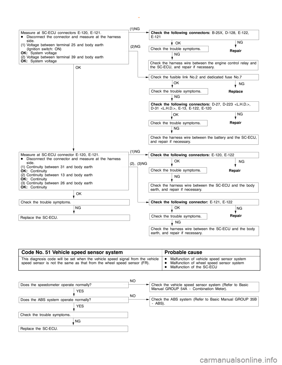
Code No. 51 Vehicle speed sensor systemProbable cause
This diagnosis code will be set when the vehicle speed signal from the vehicle
speed sensor is not the same as that from the wheel speed sensor (FR).DMalfunction of vehicle speed sensor system
DMalfunction of wheel speed sensor system
DMalfunction of the SC-ECU
NG
Check the trouble symptoms.
Replace the SC-ECU.YES
NOCheck the vehicle speed sensor system (Refer to Basic
Manual GROUP 54A - Combination Meter).Does the speedometer operate normally?
YES
NOCheck the ABS system (Refer to Basic Manual GROUP 35B
- ABS).Does the ABS system operate normally?
www.WorkshopManuals.co.uk
Purchased from www.WorkshopManuals.co.uk
Page 597 of 1839
MITSUBISHI SC-Troubleshooting13E-8
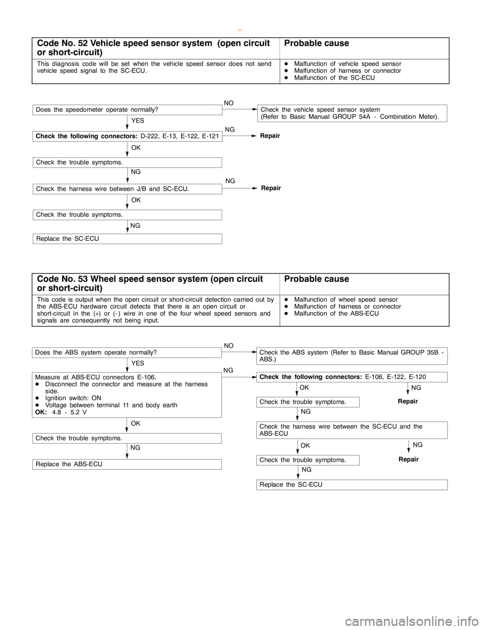
Code No. 52 Vehicle speed sensor system (open circuit
or short-circuit)Probable cause
This diagnosis code will be set when the vehicle speed sensor does not send
vehicle speed signal to the SC-ECU.DMalfunction of vehicle speed sensor
DMalfunction of harness or connector
DMalfunction of the SC-ECU
NG
OK
Repair
NG
Check the trouble symptoms.
Replace the SC-ECUNG
OK
Repair YES
NOCheck the vehicle speed sensor system
(Refer to Basic Manual GROUP 54A - Combination Meter).
NG
Check the following connectors:
D-222, E-13, E-122, E-121
Does the speedometer operate normally?
Check the trouble symptoms.
Check the harness wire between J/B and SC-ECU.
Code No. 53 Wheel speed sensor system (open circuit
or short-circuit)Probable cause
This code is output when the open circuit or short-circuit detection carried out by
the ABS-ECU hardware circuit detects that there is an open circuit or
short-circuit in the (+) or ( - ) wire in one of the four wheel speed sensors and
signals are consequently not being input.DMalfunction of wheel speed sensor
DMalfunction of harness or connector
DMalfunction of the ABS-ECU
OK
NG
Check the trouble symptoms.
Replace the ABS-ECU
OK
NG
Check the harness wire between the SC-ECU and the
ABS-ECU
Check the trouble symptoms.
NG NG
YES
NOCheck the ABS system (Refer to Basic Manual GROUP 35B -
ABS.)
Check the following connectors:
E-106, E-122, E-120
Does the ABS system operate normally?
Measure at ABS-ECU connectors E-106.
DDisconnect the connector and measure at the harness
side.
DIgnition switch: ON
DVoltage between terminal 11 and body earth
OK:
4.8 - 5.2 V
RepairNG
OK
NG
Replace the SC-ECU
Check the trouble symptoms.RepairNG
www.WorkshopManuals.co.uk
Purchased from www.WorkshopManuals.co.uk
Page 679 of 1839

ENGINE COOLING -General Information/
Service Specifications/Lubricant/Sealant14-2
GENERAL INFORMATION
The cooling system is designed to keep every part
of the engine at appropriate temperature in
whatever condition the engine may be operated.
The cooling method is of the water-cooled, pressure
forced circulation type in which the water pump
pressurizes coolant and circulates it throughout the
engine. If the coolant temperature exceeds the
prescribed temperature, the thermostat opens to
circulate the coolant through the radiator as well
so that the heat absorbed by the coolant may be
radiated into the air.The water pump is of the centrifugal type and is
driven by the drive belt from the crankshaft.
The radiator is the corrugated fin, down flow type.
ItemsSpecifications
RadiatorPerformance kJ/h6G7203,023
4D5, 4M4232,326
SERVICE SPECIFICATIONS
ItemsStandard valueLimit
High pressure valve opening pressure of radiator cap kPa74 - 10364
Range of coolant antifreeze concentration of radiator %30 - 60-
ThermostatValve opening temper-6G788±
2.0-
ature of thermostat_
C4D582±
1.5-
4M476.5±
2.0-
Full-opening tempera-6G7100-
ture of thermostat_
C4D595-
4M490-
Valve lift mm6G710 or more-
4D5, 4M48.5 or more-
LUBRICANT
ItemApplicable modelAmount (including
condense tank) L
MITSUBISHI GENUINE COOLANT or equivalentVehicles without rear heater9.0
Vehicles with rear heater10.5
SEALANT
ItemsSpecified sealantRemarks
Cylinder block drain plug3M Nut Locking Part No. 4171 or equivalentDrying sealant
www.WorkshopManuals.co.uk
Purchased from www.WorkshopManuals.co.uk
Page 1051 of 1839

FRONT AXLE -General Information26-2
GENERAL INFORMATION
The front axle consists of the front hubs, knuckles,
drive shaft, wheel bearings, ball joints, front
differential, and freewheel clutch.
The features are:
DThe structural method of press fitting unit
bearing into the front hub is applied.
DThe wheel bearing uses a taper roller unit
bearing. For vehicles with ABS, a rotor for
detecting the wheel speed is press-fitted to
the U.J. outer wheel.
DDrive shafts incorporate U.J.-B.J.-type constant
velocity ball joint has high power transmission
efficiency and reduces vibration and noise.NOTE
U.J. is an abbreviation of Under cut Joint.
DA vacuum-type freewheel clutch has been
adopted in the freewheel mechanism. Its
solenoid valve and actuator switch powertrain
between 2WD and 4WD.
DThe differential support method is a four-point
elastic support method which reduces vibration
and noise.
ItemSpecification
WheelWheel bearing typeTaper roller type unit bearing
bearingsBearing (outside diameter´inside diameter)
mm88´50
DriveJoint typeOutsideU.J.
shaftInsideD.O.J.
Shaft length
*1´Shaft diam-Right353´28
*2,361.5´26*3
eter mmLeft323´28
*2,330´26*3
InnerShaft length´Shaft diameter mm389.2´31.5
shaftBearing (outside diameter´inside diameter)
mm62´35
NOTE
*1:The shaft length indicates the length between the center points of each joint.
*2:4M41-M/T
*3:4D56, 4M41-A/T, 6G74 GDI
FRONT DIFFERENTIAL
ItemSpecification
Reduction gear typeHypoid gear
Reduction ratio4.900
*1, 3.917*2, 4.100*3, 4.300*4
Differential gear typeStraight bevel gear
NumberDrive gear49
*1,47*2, 41*3, 43*4
of teeth
Drive pinion10
*1,*3,*4, 12*2
Side gear14
Pinion gear10
NOTE
*1:4D56
*2:4M41-A/T
*3:4M41-M/T
*4:6G74 GDI
www.WorkshopManuals.co.uk
Purchased from www.WorkshopManuals.co.uk
Page 1062 of 1839
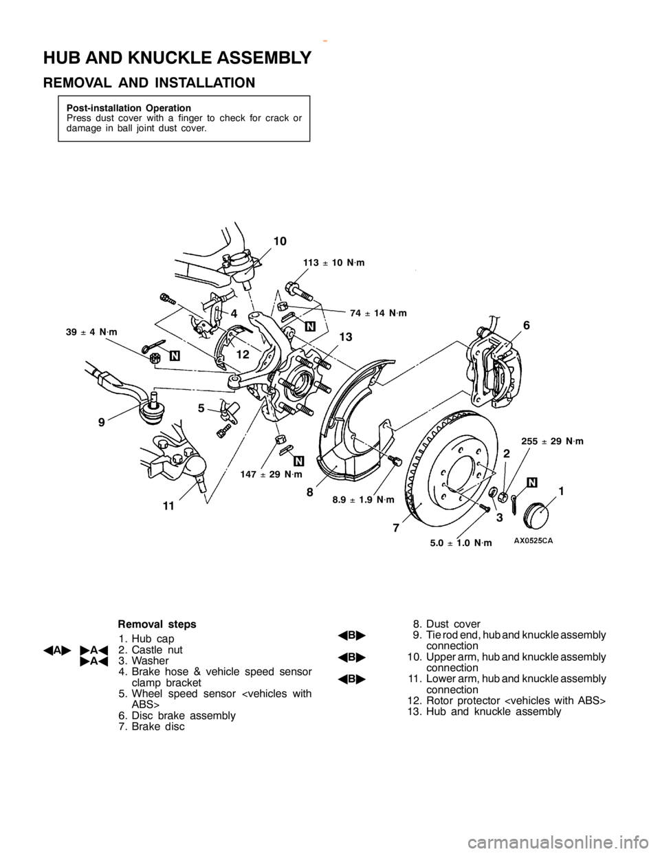
H
UB AND KNUCKLE ASSEM BLY
R EM OVA L AND IN STA LLA TIO N 34
2
15 6
89 1
0 1
1 1
2 1
3
1 47 ±
29 N×
m 7
4 ±
14 N×
m
3 9 ±
4 N×
m 1
1 3 ±
10 N×
m
8 .9 ±
1.9 N×
m
5.0 ±
1.0 N×
m 2
55 ±
29 N×
m
R em oval ste p s
1 . H ub ca p
A A"
"
AA
2. C astle nut
" AA
3. W ash er
4 . B ra ke hose & ve hic le sp eed se nso r
c la m p bra cke t
5 . W heel sp eed se nso r
6 . D is c bra ke asse m bly
7 . B ra ke dis c 8
. D ust co ve r
A B"
9. Tie ro d end,h ub and kn uckle asse m bly
c o nnectio n
A B"
10. U ppera rm ,h ub and kn uckle asse m bly
c o nnectio n
A B"
11 . Low era rm ,h ub and kn uckle asse m bly
c o nnectio n
1 2. R oto r pro te cto r
1 3. H ub and kn uckle asse m bly
w
ww.W ork sh opM an uals .c o .u k
P urc h ased f r o m w ww.W ork sh opM an uals .c o .u k